EP1514675B1 - Procédé et dispositif pour la confection et le transfert d'un ensemble bande de roulement-ceinture pour pneumatiques - Google Patents
Procédé et dispositif pour la confection et le transfert d'un ensemble bande de roulement-ceinture pour pneumatiques Download PDFInfo
- Publication number
- EP1514675B1 EP1514675B1 EP04104190A EP04104190A EP1514675B1 EP 1514675 B1 EP1514675 B1 EP 1514675B1 EP 04104190 A EP04104190 A EP 04104190A EP 04104190 A EP04104190 A EP 04104190A EP 1514675 B1 EP1514675 B1 EP 1514675B1
- Authority
- EP
- European Patent Office
- Prior art keywords
- building drum
- tread belt
- tread
- building
- shaft
- Prior art date
- Legal status (The legal status is an assumption and is not a legal conclusion. Google has not performed a legal analysis and makes no representation as to the accuracy of the status listed.)
- Expired - Lifetime
Links
Images








Classifications
-
- B—PERFORMING OPERATIONS; TRANSPORTING
- B29—WORKING OF PLASTICS; WORKING OF SUBSTANCES IN A PLASTIC STATE IN GENERAL
- B29D—PRODUCING PARTICULAR ARTICLES FROM PLASTICS OR FROM SUBSTANCES IN A PLASTIC STATE
- B29D30/00—Producing pneumatic or solid tyres or parts thereof
- B29D30/06—Pneumatic tyres or parts thereof (e.g. produced by casting, moulding, compression moulding, injection moulding, centrifugal casting)
- B29D30/08—Building tyres
- B29D30/20—Building tyres by the flat-tyre method, i.e. building on cylindrical drums
- B29D30/24—Drums
- B29D30/26—Accessories or details, e.g. membranes, transfer rings
- B29D30/2607—Devices for transferring annular tyre components during the building-up stage, e.g. from the first stage to the second stage building drum
-
- B—PERFORMING OPERATIONS; TRANSPORTING
- B29—WORKING OF PLASTICS; WORKING OF SUBSTANCES IN A PLASTIC STATE IN GENERAL
- B29C—SHAPING OR JOINING OF PLASTICS; SHAPING OF MATERIAL IN A PLASTIC STATE, NOT OTHERWISE PROVIDED FOR; AFTER-TREATMENT OF THE SHAPED PRODUCTS, e.g. REPAIRING
- B29C48/00—Extrusion moulding, i.e. expressing the moulding material through a die or nozzle which imparts the desired form; Apparatus therefor
- B29C48/03—Extrusion moulding, i.e. expressing the moulding material through a die or nozzle which imparts the desired form; Apparatus therefor characterised by the shape of the extruded material at extrusion
- B29C48/07—Flat, e.g. panels
- B29C48/08—Flat, e.g. panels flexible, e.g. films
-
- B—PERFORMING OPERATIONS; TRANSPORTING
- B29—WORKING OF PLASTICS; WORKING OF SUBSTANCES IN A PLASTIC STATE IN GENERAL
- B29C—SHAPING OR JOINING OF PLASTICS; SHAPING OF MATERIAL IN A PLASTIC STATE, NOT OTHERWISE PROVIDED FOR; AFTER-TREATMENT OF THE SHAPED PRODUCTS, e.g. REPAIRING
- B29C48/00—Extrusion moulding, i.e. expressing the moulding material through a die or nozzle which imparts the desired form; Apparatus therefor
- B29C48/15—Extrusion moulding, i.e. expressing the moulding material through a die or nozzle which imparts the desired form; Apparatus therefor incorporating preformed parts or layers, e.g. extrusion moulding around inserts
- B29C48/156—Coating two or more articles simultaneously
-
- B—PERFORMING OPERATIONS; TRANSPORTING
- B29—WORKING OF PLASTICS; WORKING OF SUBSTANCES IN A PLASTIC STATE IN GENERAL
- B29L—INDEXING SCHEME ASSOCIATED WITH SUBCLASS B29C, RELATING TO PARTICULAR ARTICLES
- B29L2030/00—Pneumatic or solid tyres or parts thereof
- B29L2030/003—Plies; Breakers
Definitions
- the invention relates to a method and apparatus for building and transferring a tread belt structure, preferably a large tread belt reinforcing structure, on a building drum to a tread belt curing mold.
- US-A- 3,865,670 teaches the use of an expansible and contractible transfer ring for conveying a breaker tread assembly from a building drum in a tire building machine to a tire carcass mounted on a tire shaping machine.
- US-A- 3,865,669 discloses an expansible and contractible transfer ring for conveying a breaker-tread assembly.
- tread belt pneumatic tires which are subject to the method of the present invention are very large tires (greater than 119.9 inches outside diameter (OD)) generally designed for use on very large vehicles, generally off-the-road vehicles such as earthmovers and large capacity mining trucks (e.g., 300 short tons or more).
- OD outside diameter
- the tread belt alone will weigh over 1814.4 kg (4,000 pounds) typically, many times more depending on the size.
- a 57 inch nominal rim diameter two-piece tire having a 45R57 size will have a tread belt assembly having an outside diameter of approximately 12 foot or roughly 144 inches and will weigh approximately a little more than 2041,2 kg (4,500 pounds), a smaller but still very large 51 inch nominal rim diameter tire of a 3300R51 size yields a 1360.8 kg (3000 lb.) tread belt, and the massive 63 inch 59R63 tire has a tread belt weighing in at 3821.1 kg (8424 lbs).
- US-A- 4,304,619 discloses a method and apparatus for off-loading uncured tires. This method includes engaging the completed tire coaxially within a ring having radially movable segments and then moving the ring with the tire coaxially off the building machine to a chucking device engageable with the inner peripheries of the respective bead portions of the tire. The ring is then expanded and moved coaxially from the tire and the chucking device now holding the tire is rotated to place the tire axis in vertical orientation and elevated to a position above the tire machine where the exterior surface of the tire is grasped by a pair of palms mounted on a swing arm. After the chucking device is moved downwardly clear of the tire, the tire is then moved horizontally by the swing arm and deposited on an overhead belt conveyor to be transported thereby to further processing.
- EP-A- 0343426 discloses a second stage tire building machine including a first station for receiving and supporting a first stage tire carcass; a second station axially offset from the first station for assembling a breaker and tread cylinder; a transfer ring to transport the breaker and tread cylinder from the second station onto the periphery of a carcass at the first station for the assembly of a green tire and to then transport a green tire to an intermediate location; and a robot to transport a carcass to the first station and a green tire from the transfer ring.
- a method of building and transferring a tread belt structure on a portable and collapsible building drum mounted coaxially on a building machine with a rotatable shaft according to claim 1 is disclosed.
- the step of forming the annular tread belt further may include the additional steps of claim 2. While the steps of forming the tread belt are being accomplished, the steps of weighing the building drum as the tread belt is being formed annularly may be accomplished through the use of sensors, preferably strain gauges, preferably attached to the rotating shafts supporting the building drum. The step of weighing the material as it may be applied enables to adjust the amount of elastomeric material to be applied to form the tread belt to match the weight or volume at a known specific gravity of the elastomeric material to the predetermined specification weight or volume.
- the weight of the tread belt can be established using deflection sensors to measure the movement of the cantilevered shaft.
- the weighing of the tread belt may be further confirmed by the use of load cells at the transfer means or, alternatively, at the building machine.
- the steps of forming the elastomeric layers are accomplished by calendering or extruding strips or sheets of unvulcanized rubber at the tread belt building machine.
- the steps of controlling the weight of the elastomeric material is preferably accomplished by adjusting the gauge of the material as a function of the monitored weight of the building drum or by increasing the number of windings of the unvulcanized rubber by an increased rotation of the building drum.
- an apparatus for building and transferring a tread belt reinforcing assembly which has a drive means for rotating a building drum, the drive means including a drum supporting shaft, a building drum for applying the elastomeric components and a weight sensor connected to the drum supporting shaft for measuring and monitoring the amount of rubber applied to the building drum, or the deflection sensor or load cells used to perform the weight sensing.
- Weight measuring is best accomplished by a computer controlled means for adjusting the amount of material being applied to the building drum.
- the computer controlled means analyzes the weight sensor data to direct increases or decreases in material being applied.
- the apparatus further includes at least one means for strips of elastomeric material to be applied to the building drum, the at least one means also being controlled by the computer control means, preferably at least the means for supplying the layers of tread rubber is controlled to adjust the tread belt weight.
- the invention also relates to an apparatus according to claim 5.
- the entire building drum is slidably movable on the shaft and is moved directly onto the coaxially aligned transfer shaft.
- the removable building drum is collapsible and has a tread belt building surface.
- the tread belt building surface is preferably formed by a plurality of arcuate segment assemblies.
- Each segment assembly is radially contractible.
- Each segment may be connected to a pair of hydraulic or air cylinders internally positioned between the arcuate segment and a central hub.
- each segment assembly includes a trapezoidal support and an arcuate building surface, wherein each trapezoidal support has the radially inner portion narrow and the sides of all the adjacent trapezoids are contacting to form a 360° rigid frame when in either the fully extended or retracted position.
- the building surface arcuate segments are alternating arcuate segments having the inner portion narrow and the outer portion wider and the inner portion wider and the outer portion narrower in each adjacent pair creating an alternating pattern that permits the outer surface to form a complete peripheral surface for building the tread belt assembly in a fully supported manner and which permits each segment to be retracted in an alternating position for tread belt removal.
- the building surface arcuate segments are alternating arcuate segments having the inner portion narrow and the outer portion wider and the inner portion wider and the outer portion narrower in each adjacent pair creating an alternating pattern that permits the outer surface to form a complete peripheral surface for building the tread belt assembly in a fully supported manner and which permits each segment to be retracted in an alternating position for tread belt removal.
- four will have the outer portion wider and inner portion narrower and four will have the outer portion narrower and inner portion wider so that the segments may be retracted in a sequence and expanded in a sequence to form the building surface and to permit a contraction so the tread belt can be released in a convenient and efficient manner.
- Belt or breaker reinforcing structure/assembly means at least two layers of plies of preferably parallel cords, woven or unwoven, underlying the tread, unanchored to the bead, and having both left and right cord angles in a preferred range from 17° to 75° with respect to the equatorial plane of the tire.
- “Circumferential” means lines or directions extending along the perimeter of the surface of the annular tread perpendicular to the axial direction.
- Equatorial plane means the plane perpendicular to the tire's axis of rotation and passing through the center of its tread.
- “Lateral” and “laterally” mean lines or directions that are parallel to the axis of rotation of the tire (also “axial).
- Ring and radially mean directions extending radially toward or away from the axis of rotation of the tire.
- Cross-sectional views may be in the form of slices or near-sided cross-sectional views omitting certain background lines which would otherwise be visible in a true cross-sectional view, for illustrative clarity.
- a method and apparatus for forming a tread belt is disclosed.
- a system for forming a tread belt assembly for a large two piece tire assembly is shown.
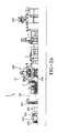
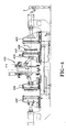
- the system 1 as illustrated in Figure 2B has a tread building drum 10 attached to a means 100 for building the tread belt assembly and a transfer means 200 for accepting the tread belt assembly 4 and the building drum 10.
- Figure 2A shows a portion of system 1 from an elevation or side view.
- the means 100 for building the tread belt 4 is positioned about midway between the various mechanisms for forming the components that make the tread belt assembly 4
- FIG. 1 an overhead view of the system 1 is illustrated.
- the means 100 has various mechanisms on each side of the building shaft 120. As shown, the building drum 10 and the rail mechanism 130 which permits the means 100 to move between a first position A and a second position B are not illustrated. As shown in Figure 1, the means 100 is located in position B.
- the formed tread belt assembly 4 is comprised of various components which are described in US-A- 6, 561,211 .
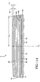
- the tire tread belt 4 includes a tread portion 80 and a plurality of tread belts 84, 86 and 88.
- a radially inner belt layer 84 and 86 have cords of steel having a core strand surrounded by a sheath of strands.
- the core strand preferably has a plurality of three filaments forming the core.
- the wire construction is as described in US-A-6,272,830 .
- Each tread belt layer 84, 86 has the cords oriented at an angle of 15° to 80° relative to the circumferential direction and the cords are preferably spaced at 4 ends per inch.
- the radially outermost third layer 88 has steel cords oriented at 90° relative to the circumferential direction. This, in combination with the belt layers 84, 86 creates a very strong construction. Radially inward of these belt reinforcement layers is a unique first reinforcement layer 90 having cords 92 oriented 0° or approximately 0° relative to the circumferential direction and preferably spaced at three ends per inch.
- tread belts 84 through 88 are illustrated, it is within the scope of the invention to use any other number of tread belts layers as needed.
- the unique aspect of the tread belt is the use of 0° wire cord 92 in the first reinforcement layer 90.
- the 0° wires in layer 90 encircle the tire tread belt and are provided to restrict the radial growth of the tread belt due to serious deflection in the tire carcass. By keeping the tread belt from radially expanding outwardly the tire's tread will maintain a more flat tread profile which will improve tread life and durability.
- the 0° wires in the first reinforcement layer eliminate the need for a larger number of belt layers.
- a plurality of strips 72 and grooves 74 Radially inward of the 0° wires 92 along the under side or inner circumference of the tread belt is a plurality of strips 72 and grooves 74.
- the strips 72 form ribs on the inner surface of the tread belt assembly when the tire is molded.
- Each strip 72 is spaced a distance sufficient to form a groove 74.
- These grooves and ribs interconnect with the mating tire casing when assembled.
- the tread belt 4 as illustrated in Figure 14 is best assembled using the method described below employing the system 1 as illustrated in Fig. 1.
- the first step in the assembly of the tread belt 4 has the means 100 for forming the tread belt located at position A at which point strips 72 are placed in the grooves on the building drum 10. This initial layup of strips 72 filling the grooves on the building drum 10 form the first or inner surface layer.
- the means 100 is then moved back to position B wherein an inner cover layer is applied from the gum server means 180 having a pair of A frame trucks 182 loaded with gum layers material.
- the inner cover layer 74 may be three or four windings on the building drum and form additional elastomeric inner surface for the tread belt 4.
- the means 100 is then moved to position A wherein a mechanism feeds rubber encapsulated wires 92 spirally or helically wound at an angle close to 0° at least one full wrap around the circumference of the tread drum 10.
- a mechanism feeds rubber encapsulated wires 92 spirally or helically wound at an angle close to 0° at least one full wrap around the circumference of the tread drum 10.
- gum wedges 75, 77 are applied to the edges of the tread belt forming a complete second layer.
- the 0° wires 92 is fed from one or more wire let-off mechanisms 352 in synchronization with the rotating building drum.
- An extruder 354 feeds encapsulating rubber through a die 355.
- a cable puller 356 pulls the strands to the safety festoon 357 which feeds the rubber coated wires 92 through the means 360 for applying the wires 92 to the building drum 10.
- the means 360 includes a level wind head 362 to insure the cords 92 are spirally wound precisely located on the building drum 10. The coated wires 92 are applied while the rubber is still warm insuring a much-improved adhesion.
- the method of encapsulating the wires 92 at the building system 1 permits the coated wires 92 to be placed on the building drum 10 while the uncured rubber is hot. The rubber naturally adheres better and provides the compound to be made without using costly tackifiers and anti-blooming agents.
- the encapsulated wires 92 are fed through the die 355 in pairs of two cables. This insures the rubber-coated wires have a rectangular shape making the wires easy to spirally wind onto the drum 10.
- the wires 92 can optionally be wound using two separate feed lines starting from the lateral edges of the building drum 10 and moving to the center of the building drum 10 effectively cutting revolutions of the drum 10 in half.
- the die 355 may include more wires 92 to form a strip of three or more encapsulated wires.
- the means 100 is then moved back to position B wherein belt layers are applied to the building drum, belt layer 84 being in a left hand direction having the cords oriented on a slight bias angle as previously noted and a second layer is wrapped around the cords in an opposite but equally oriented direction forming belt layer 86.
- belt layer 84 being in a left hand direction having the cords oriented on a slight bias angle as previously noted and a second layer is wrapped around the cords in an opposite but equally oriented direction forming belt layer 86.
- additional gum wedges or filler strips 75, 77 are wrapped around the belt layers 84, 86 to complete the assembly of the third and fourth layers.
- one wrap of 90° cord is placed around the tread belt assembly and filler strips 75, 77 are added to the edges form the belt layer 88.
- the means 150 for applying the breaker or belt layers 84, 86, 88 are shown just below the means 100 in Figure 1.
- a pair of A frame trucks 152 for supplying the belt layers are adjacent the means 150. The operator applies each belt layer 84, 86, and 88 and forms a spliced but joint parallel to the direction of the cords in each respective layer.
- the means 100 is then moved forward into the position A wherein a hot former calender assembly 450 shown on the right hand side of the figure feeds layers of tread rubber to the drum 10 as it is rotated.
- the layers 81 of tread rubber 80 are approximately .08 inches thick at the center and are wrapped about the tread belt assembly 4 for about a total thickness of four inches.
- Each layer 81 has a profiled center portion that is slightly thicker than the lateral edges of the layer 81. This is because the calender rollers 40 are profiled slightly to provide a slight angle on each layer 81. As the tread 80 is being applied, the contour of the tread becomes more pronounced upon each layer 81 being formed.
- the profile of the layers 81 permits a uniform flow of tread rubber in the curing mold 400.
- the profiling of the layers 81 may change based on the tread pattern being molded.
- the hot former 450 includes a stock feed 452, an extruder 454 to process the rubber strips, a plurality of rollers 457 and a pair of calender rollers 456 to form continuous sheets or layers 81 of tread rubber. Once formed the sheets or layers are moved along a conveyor cooling belt 458 to be applied to the building drum 10 at the maximum temperature without prematurely initiating tread cure. This maximum tread temperature is about 160°F which when placed in the mold shortens the cure cycle and wherein this continuous winding of hot layers 81 is accomplished to form the tread 80.
- the hot former means 450 may be substituted by a sheet laminator.
- Sheet laminators take extruded rubber and form sheets of rubber. Like the means 450 the sheet laminator can deliver the sheets or layers 81 to the building drum 10 while hot. The ability of building the tread belt 4 with hot components such as the tread layers 81 can greatly shorten the mold curing time.
- the means 100 is shown in position B with the tread belt assembly being shown as a dash line.
- the means 100 is moved forward to position A, it is in direct axial alignment with the shaft 220 of the transfer means 200 as shown.
- the means 100 is in position A and is ready to have the tread belt 4 mounted on the building drum 10 transferred to the transfer means 200 once the assembly is completely assembled.
- a pusher means 280 is used to drive the tread drum assembly from the building shaft 120 and on to the transfer shaft 220.
- the tread belt 4 has the lateral edges precisely located.
- the building drum assembly 10 has the tread belt 4 lateral edges trimmed such that the lateral edge is pushed into contact with six spaced stops on the means 200 as the drum 10 is pushed fully onto the transfer shaft 220 to a mechanical stop on the transfer means 200. This insures the weight of the tread belt is supported on the lateral edges when the transfer means is pivoted horizontally.
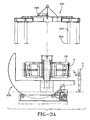
- the operator 2 can back up the building means 100, clearing the transfer means 200 and then pivotally rotating the transfer means 200 so that the tread belt 4 and building drum 10 are now laying in a horizontal position; that is, the axis of the transfer shaft 220 is facing in a vertical position and the tread belt circumference is lying in a horizontal plane as shown in Figure 3A.
- a motor 223 is actuated driving a roller 225 which rolls the means over the rollers 224 as shown.
- an overhead pickup device 300 is illustrated.
- the overhead pickup device 300 as shown in 3A is positioned directly over the tread belt 4 and drum assembly 10 and is then lowered over the tread belt assembly 4.
- Vertically extending legs 302 with feet 304 are provided so that they can pick up the tread belt 4.
- legs 302 of the pickup device 300 are able to traverse over and encircle the tread belt 4. They are then rotated simultaneously inwardly by contracting the motor gearbox 306 such that the feet 304 on the legs 302 can grab a lateral edge of the tread belt 4 and pull it from the building drum 10.
- the legs 302 of the pickup device 300 Prior to the pickup device 300 being able to remove the tread belt 4 from the building drum 10, the legs 302 of the pickup device 300 are raised applying a lifting force approximately equal to the tread belt weight.
- the transfer means 200 has load cells 221 in the base of the apparatus such that the operator can read a scale readout to determine when the exact amount of the lifting force is applied to the lateral edges or this can be computer controlled automatically. This effectively balances the tread belt 4 at a weight of zero on the building drum 10. This insures the internal ribs 72 will not be torn as tread belt 4 is removed. After the weight is balanced then the building drum 10 can be collapsed in a radially contracted position to free the tread belt 4 from the building drum 10.
- the entire loaded mechanism is moved over a segmented mold cure station 400 that has been opened with the radially inner segment assemblies 404 retracted radially inward and the radially outer segment assemblies 402 expanded outwardly so that the assembly 4 can be lowered in between the inner segment assemblies 404 and outer segment assemblies 402 of the mold.
- the tread belt 4 is positioned several of the inner segment assemblies 404 can close about the inner circumference of the tread belt assembly such that the grooves 72 or ribs 74 are lined up with the grooves 420 or ribs 440 of the mold 400 and then several of the outer segment assemblies 402 partially close.
- the pickup transfer device 300 is no longer required to support the tread belt 4 as the tread will be fully supported by the mold 400.
- the pickup transfer device 300 is then extracted from the mold 400 and the remaining inner and outer segment assemblies 404, 402 can close on the tread belt assembly 4 for the molding process.
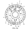
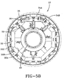
- FIG. 5A the view looking into the building drum 10 towards the axis of rotation is illustrated.
- the building drum 10 is shown in the fully radially expanded position.
- Figure 5B the building drum 10 is shown in a radially collapsed position, the dash lines showing the radially expanded position.
- the tread belt building surface 120 of the building drum 10 is formed by a plurality of arcuate segment assemblies 30. Each segment assembly 30 is radially contractible. Each segment assembly 30 is connected to a mechanically locking air or hydraulic cylinder 33 internally positioned between the arcuate segment 34A, 34B and the central hub 40. These mechanical locking cylinders 33 once extended are mechanically locked in the extended position until re-energized.
- Each segment assembly 30 includes a trapezoidal support 32 and arcuate building surface segments 34.
- Each trapezoidal support 32 has a radially inner portion 32A narrow and the sides 32C of all adjacent trapezoids are in full contact to form an octagonal 360° rigid frame when the building drum 10 is either in the fully extended or fully retracted position.
- the arcuate building surface 34 has a plurality of segments that are alternating arcuate segments 34A having the inner portion narrow and the outer portion wider and arcuate segments 34B the inner portion wider and the outer portion narrow in each adjacent pair creating an alternating pattern that permits the outer surface 34 to form a complete peripheral surface for building the tread belt assembly 4 in a fully supported manner and which also permits each arcuate segment 34A, 34B to be retracted in an alternating pattern for tread belt removal. For example, there are eight quadrants as shown.
- arcuate segments 34A will have the outer portion wider and inner portion narrower and four arcuate segments 34B will have the outer portion narrower and the inner portion wider so that the arcuate segments 34A, 34B can be retracted in a sequence and expanded in a sequence to form the building surface 34 and to permit a contraction so that the tread belt 4 can be released in a convenient and efficient manner.
- Each arcuate segment assembly 30 has four shafts 35 and bearings 36 connected to the trapezoidal support 32. These bearings 36 and shafts 35 permit slidable movement of the arcuate segment 34 when the cylinder 32 is actuated.
- Each cylinder 33 is connected to a central manifold 37. Air is provided in a fashion to direct an expansion or contraction of the arcuate segment 30 as a function of the cylinder 33 being actuated.
- these features permit the tread belt assembly 4 to be formed on a fully supported arcuate circular building drum 10 which can be easily retracted permitting the removal of the tread belt assembly when placed in the transfer device 200.
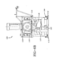
- the means 100 for forming the tread belt assembly 4 is shown in an enlarged view.
- the means 100 for forming is mounted on a rail system 130 that permits slidable movement of the entire assembly 100 so that the tread belt components can be applied in either position A or position B as previously noted.
- Attached to the frame 110 are linear bearings 112 that permit easy and simple slidable movement of the entire mechanism 100.
- All of the electronics and wiring are provided on a flexible cable 132 as illustrated above such that the entire wiring harness 132 can be moved and permit movement from position A to position B and back without impeding the ability of the equipment to function.
- the means 100 as shown in Figures 6A, 6B and 7 has a means 127 for measuring the rotational surface speed of the components applied to the building drum 10.
- the speed of the surface of the components on the building drum at a given diameter is fed back to the means 360 for applying the encapsulated wires 92 to insure the layer 90 of wires 92 is applied at the same speed as the drum winds.
- speed of calendering the sheets or layers 81 of tread rubber is tied to the surface speed of the drum 10 so that as the diameter of the layers increases just the right amount of rubber is fed to the drum as it rotates.
- a non-contacting speed sensor 127 feeds the speed back to control computers to keep each machine in synchronization.
- the centerline laser light 128 provides an indication of the edge straightness of the layers as they are applied. Precise edge control insures all the layers are properly applied.
- Movement of the means 100 from position A to position B is directed by empowering a small motor 102 as illustrated connected to a slip clutch 103 and gears 104 that provide movement of the assembly relative to the rails 130.
- the movement of the entire means 100 is precisely controlled and an encoder device 109 is provided to know the actual position and relative movement of the building drum 10 such that it can be properly centered and positioned from movements from A to B in a very precise manner.
- a tapered drive pin 107 presses into the floor assembly 108 when the means 100 is in its proper position either in A or B and is retracted to enable the equipment to move. Although the equipment weighs several tons, the movement on the linear bearing 112 is basically very low friction and can be easily moved by pushing the means 100 as so desired.
- a pair of locking assemblies 109 such as those formally referred to as Ringfeder®, are shown mounted to the shaft 120 and connected to the locking assemblies 109 is an air brake 114. This provides for rapid and quick stopping of the rotation of the building drum 10.
- a hydraulic reservoir 115 and pump 116 On the lower left hand side of the means as illustrated in Figure 6A is a hydraulic reservoir 115 and pump 116.
- a 20 horsepower motor 117 Next to the hydraulic reservoir 115 and pump 116 and mounted to the frame 110 is a 20 horsepower motor 117.
- the 20 horsepower motor 117 is connected to the shaft gears 118 by a chain 119.
- the entire shaft 120 is chain driven.
- the shaft 120 is supported by two large split free bearings 121.
- an enlarged pusher plate 280 At the cantilevered end of the shaft 120 is an enlarged pusher plate 280.
- Attached to the pusher plate 280 is a dog drive 282 and interconnected to the building drum 10 is a mating dog drive assembly 283.
- These dog drives 282, 283 intermesh and provide a driving means for the building drum 10.
- Two cylinders 101 on each side of the means 100 provide for movement against the pusher plate 280 to push the entire building drum assembly 10 onto the transfer means 200.
- Each cylinder 101 is connected using a self-aligning coupling 105 to prevent the mechanism from binding under load differentials.
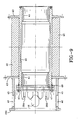
- the shaft 120 is comprised of hollow tubular cylinders 123A, 123B with flanges 122, 124 at the midpoint. These flanges 122, 124 provide a connection from the internally supported shaft cylinder 123A and the externally cantilevered cylinder 123 and phantom lines show the hub 40 of the building drum assembly 10 as shown.
- the radially outer end of the shaft is tapered with a mechanical stop.
- an air fitting 129 that is provided just to facilitate the operator 2 and in case he needs an airline connected he can connect at the shaft distal end fitting 129.
- the drive gear 118 is shown attached to the gear sprocket end 128 which enables rotational movement to be transmitted to the shaft.
- the hub 40 of the building drum 10 is illustrated. As shown there are a pair of naval bronze bearings 41 that are used to fit directly onto the cantilevered portion of the shaft 120. Each bearing 41 has a tapered end and provides slidable movement on the shaft 120 so that the entire building drum assembly 10 can be moved back and forth.
- the hub 40 shows gussets 42 provided for additional support and strengthening of the hub assembly 40.
- the gussets 42 are positioned between the two annular plates 43 of the hub assembly as illustrated.
- An outer sleeve 45 is provided with a hole 46 in several locations so that access can be provided to the shaft 120 once the building drum 10 is mounted on the shaft 120 should there be a need to do repair work on the shaft 120 while the building drum 10 is mounted on it.
- the dog drive 283 is bolted with bolts 47 directly to an end plate 49 on the hub assembly.
- This dog drive 283 provides drum rotational movement.
- At the far lefthand side of the building drum hub as shown in Fig. 9 is the pusher plate 280.
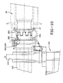
- the dog drive 282 that is mounted to the main shaft or drive shaft 120 of the means 100 is illustrated.
- the dog drive 282 only has two teeth 285 at each location 0° and 180°.
- a key slot 290 is shown such that the dog drive 282 can be precisely mounted.
- the key slot is shown on the annular flange 286 of the dog drive 282.
- Holes 292 are provided for attaching the dog drive 282 to the shaft 120.
- Threaded fasteners 294 are used for the purpose of securing the dog drive 282 to the shaft 120.
- a means 500 for weight measuring the tread belt 4 as it is being formed can be provided.
- the means 500 for measuring consisted of strain gauges 502 positioned between the drive dog 282 mounted on the shaft 120 and the shaft 120. These strain gauges 502 measure the strain of the shaft 120 and can translate that to a weight. It was determined that by having the weight transmitted through diametrically opposed teeth 285 that no binding or misreading of weight can occur. In other words, all weight transfer occurs through the teeth 285 directly above and below the teeth 285, thereby positioning the strain gauge 502 between these teeth 285 would provide a very accurate way of measuring the weight of the tread belt assembly 4 as it is being formed. Measurements are taken as the tread belt 4 is applying the various components.
- the means 500 for measuring when connected to a computer with software designed to indicate to the operator that he has in fact applied the necessary components in the necessary amount as the belt 4 is being formed means that each application of components would have a specific weight and that weight would be fed into the computer, and as the tread belt is being built the accumulated weight of each component as it is added can be measured and compared to the specification.
- An additional feature that has been beneficial to the manufacturer of the tread belt 4 is that if a layering of tread rubber 80 is found to be either deficient in the amount of material or is being applied at too rapid a rate, it is possible for the operator to adjust the number of windings so that the rotation of the drum 10 can be stopped either on a fraction or a multiple of additional rotations to ensure that the proper tread belt weight is formed when the tread belt 4 is being assembled. This is particularly useful when one is building a tread belt 4 using relatively thin layers 81 of tread rubber 80. As illustrated, the tread 80 is wound in layers 81 approximately 2.03 mm (0.080 inch) at the center and 14 mm (0.55 inches) at the tread edges to a total thickness of approximately four inches at the center.
- tread rubber 80 being applied is slightly light or slightly heavy the operator can simply stop the rotation at the precise weight required. It has been determined that in the manufacture of tires, for example, calendered material that is used in making treads can vary by as much two to four percent. If this occurs, the weight of the tread being applied to the tire can be off by a few pounds. This has both an economic impact and a uniformity concern. With a tread belt that weighs approximately 1814.4 kg (4,000 pounds) a 2% deviation in weight can be in error as much as 36.2 kg (80 pounds).
- the inventors have found that the variations in specific gravity of the rubber layers can influence the volume of the tread belt.
- the application of the tread rubber can be adjusted by knowing the specific gravity of the tread rubber prior to calandering of the sheet or layers 81. Accordingly, the amount of rubber to be used on a given tread belt 4 can be varied based on the specific gravity of the tread rubber.
- the weighing of the tread belt 4 has been described. By knowing the specific gravity of the rubber the required weight can be calculated and the computer controlled equipment can apply the precise amount of material within a few pounds.
- the mold 400 having rigid external and internal segments means the curing volume is fundamentally fixed. Accordingly, if the volume of the tread belt 4 varies by a large amount the mold either will not close properly or the tread will not be fully developed.
- the present apparatus provides a system which enables the manufacture of tread belts to be done in a very precise manner without significant variation in tread weight.
Landscapes
- Engineering & Computer Science (AREA)
- Mechanical Engineering (AREA)
- Tyre Moulding (AREA)
Claims (9)
- Procédé de confection et de transfert d'une structure de ceintures de bande de roulement (4) sur un tambour de confection (10) portable et apte à s'affaisser, qui peut être monté sur une machine de confection (100) comportant un arbre rotatif (120), le procédé comprenant les étapes consistant à :former une structure de ceintures de bande de roulement (4) sur le tambour de confection (10) monté sur l'arbre rotatif (120) ;transférer le tambour de confection (10) avec la structure de ceintures de bande de roulement (4) de l'arbre rotatif (120) à un dispositif de transfert pivotant (200) ;faire pivoter le dispositif de transfert (200) sur environ 90° pour amener la structure de ceintures de bande de roulement (4) et l'axe du tambour de confection perpendiculairement à un plan horizontal ;affaisser le tambour de confection (10) ;séparer la structure de ceintures de bande de roulement (4) du tambour de confection (10) ;retirer la structure de ceintures de bande de roulement (4) ;élargir le tambour de confection (10) ;faire pivoter le tambour de confection (10) pour l'amener en alignement coaxial avec l'arbre rotatif (120) ;déplacer le tambour de confection (10) sur l'arbre rotatif (120).
- Procédé selon la revendication 1, dans lequel l'étape de formation de la structure de ceintures de bande de roulement (4) englobe les étapes consistant à :appliquer au moins une première couche de caoutchouc de bande de roulement sous la forme de plusieurs premiers rubans de bande de roulement sur le tambour de confection rotatif (10) ;appliquer une ou plusieurs couches renforcées avec des câblés par-dessus ladite au moins une première couche de caoutchouc de bande de roulement tout en faisant tourner le tambour de confection (10) ; etenrouler une ou plusieurs couches de caoutchouc de bande de roulement sur les couches sous-jacentes de caoutchouc et de câblés pour former la structure de ceintures de bande de roulement (4).
- Procédé selon la revendication 2, comprenant en outre l'étape consistant à appliquer un contrepoids sur le tambour de confection (10) lorsque la formation de la structure de ceintures de bande de roulement est de type annulaire.
- Procédé selon la revendication 1, comprenant en outre les étapes consistant à :saisir la structure de ceintures de bande de roulement (4) le long des bords latéraux inférieurs en utilisant un moyen de préhension ; etappliquer une force pour contrebalancer de manière efficace le poids de la structure de ceintures de bande roulement (4) avant d'affaisser le tambour de confection (10).
- Appareil pour la confection de transfert d'une ceinture de bande de roulement ou d'un assemblage de renforcement de ceintures de bande de roulement, comprenant :un moyen d'entraînement pour faire tourner un tambour de confection (10), le moyen d'entraînement englobant un arbre (120) s'étendant à l'horizontale supportant le tambour de confection ;un tambour de confection apte à s'affaisser en direction radiale, monté en coulissement sur l'arbre de support (120) du tambour de confection ;un moyen de transfert (200), le moyen de transfert englobant un arbre de transfert fixé à un bâti mobile en pivotement, l'arbre de transfert étant à même de pivoter pour venir se mettre en alignement coaxial avec l'arbre (120) du tambour de confection pour un transfert du tambour de confection et étant à même de pivoter à la verticale pour le retrait de la ceinture de bande de roulement ou le retrait de l'assemblage de renforcement de ceintures de bande de roulement ;un moyen pour faire passer la ceinture de bande de roulement (4) ou l'assemblage de renforcement de ceintures de bande de roulement de l'arbre de support du tambour de confection à l'arbre de transfert.
- Appareil selon la revendication 5, dans lequel le tambour de confection (10) apte à s'affaisser possède une surface de confection de ceinture de bande de roulement, la surface de confection de ceinture de bande de roulement étant formée par plusieurs assemblages de segments de forme arquée, chaque assemblage de segment étant apte à se rétracter en direction radiale.
- Appareil selon la revendication 5, comprenant un détecteur du poids relié à l'arbre de support (120) du tambour de confection.
- Appareil selon la revendication 7, comprenant en outre un moyen commandé par ordinateur pour régler la quantité de matières appliquée sur le tambour de confection (10), le moyen commandé par ordinateur étant configuré pour analyser les données fournies par le détecteur du poids dans le but d'augmenter ou de diminuer directement la quantité de matière.
- Appareil selon la revendication 7 ou 8, comprenant en outre au moins un moyen pour former des rubans de matière élastomère à appliquer sur le tambour de confection (10), les moyens étant configurés pour être commandés par le moyen de commande informatique.
Applications Claiming Priority (2)
| Application Number | Priority Date | Filing Date | Title |
|---|---|---|---|
| US658501 | 1996-06-05 | ||
| US10/658,501 US20050051256A1 (en) | 2003-09-09 | 2003-09-09 | Method and apparatus for building and transferring a tread belt structure |
Publications (3)
| Publication Number | Publication Date |
|---|---|
| EP1514675A2 EP1514675A2 (fr) | 2005-03-16 |
| EP1514675A3 EP1514675A3 (fr) | 2005-09-14 |
| EP1514675B1 true EP1514675B1 (fr) | 2008-01-23 |
Family
ID=34136741
Family Applications (1)
| Application Number | Title | Priority Date | Filing Date |
|---|---|---|---|
| EP04104190A Expired - Lifetime EP1514675B1 (fr) | 2003-09-09 | 2004-09-01 | Procédé et dispositif pour la confection et le transfert d'un ensemble bande de roulement-ceinture pour pneumatiques |
Country Status (6)
| Country | Link |
|---|---|
| US (2) | US20050051256A1 (fr) |
| EP (1) | EP1514675B1 (fr) |
| JP (1) | JP2005081845A (fr) |
| BR (1) | BRPI0403808A (fr) |
| DE (1) | DE602004011437T2 (fr) |
| ES (1) | ES2320341T3 (fr) |
Families Citing this family (17)
| Publication number | Priority date | Publication date | Assignee | Title |
|---|---|---|---|---|
| ITTO20021123A1 (it) * | 2002-12-24 | 2004-06-25 | Marangoni Tread S P A | Metodo ed impianto per la realizzazione di un anello di battistrada di materiale elastomerico vulcanizzato da applicarsi ad una carcassa di pneumatico. |
| US20070175567A1 (en) * | 2005-11-10 | 2007-08-02 | David Stahl | Methods and apparatus for making tires and for converting an assembly line for making different types of tires |
| JP4680270B2 (ja) * | 2006-02-08 | 2011-05-11 | 東洋ゴム工業株式会社 | グリーンタイヤの検査装置とその方法 |
| JP5342318B2 (ja) * | 2009-05-11 | 2013-11-13 | 株式会社ブリヂストン | タイヤの製造方法およびそれに用いられるタイヤ成型機 |
| WO2011065951A1 (fr) * | 2009-11-30 | 2011-06-03 | Michelin Recherche Et Technique S.A. | Procédé de commande de volume de produit dans un moule à volume fixe |
| DE102010000366B4 (de) | 2010-02-11 | 2023-09-28 | Continental Reifen Deutschland Gmbh | Verfahren zur Herstellung von Fahrzeugreifen bei dem Materialstreifen aus einer Rohgummimischung auf eine Reifenaufbautrommel aufgespult werden |
| WO2012150948A1 (fr) | 2011-04-30 | 2012-11-08 | Michelin Recherche Et Technique S.A. | Procédés et appareils permettant d'assembler des bandes de roulement |
| BR112013033157A2 (pt) | 2011-06-30 | 2017-01-31 | Michelin & Cie | métodos e aparelhos para a instalação de um anel de banda de rodagem e uma carcaça de pneu |
| JP6134810B2 (ja) | 2012-12-18 | 2017-05-24 | コンパニー ゼネラール デ エタブリッスマン ミシュラン | 官能基種のゴムへのグラフト化 |
| CN105034423A (zh) * | 2015-09-08 | 2015-11-11 | 杭州朝阳橡胶有限公司 | 一种轮胎成型机胎面供料架 |
| CN105751545B (zh) * | 2016-03-30 | 2017-12-08 | 萨驰华辰机械(苏州)有限公司 | 一种钢圈分离系统及其对应的钢圈分离方法 |
| JP6740825B2 (ja) * | 2016-09-08 | 2020-08-19 | 住友ゴム工業株式会社 | タイヤの製造方法 |
| NL2018974B1 (en) * | 2017-05-24 | 2018-12-07 | Vmi Holland Bv | Assembly and method for processing bead-apexes |
| EP3717224B1 (fr) * | 2017-11-27 | 2023-01-04 | Pirelli Tyre S.p.A. | Procédé de fabrication de pneus et appareil pour fabriquer des pneus pour roues de véhicule avec un dispositif de transfert |
| US20190184657A1 (en) * | 2017-12-19 | 2019-06-20 | The Goodyear Tire & Rubber Company | Method and apparatus for forming rubber reinforced component |
| CN110406143A (zh) * | 2019-08-27 | 2019-11-05 | 杭州朝阳橡胶有限公司 | 一种在轮胎内部自动贴合tpms传感器的系统 |
| CN113463935B (zh) * | 2021-07-21 | 2023-03-14 | 中建二局第二建筑工程有限公司 | 一种高强度钢筋楼板施工防践踏装置 |
Family Cites Families (34)
| Publication number | Priority date | Publication date | Assignee | Title |
|---|---|---|---|---|
| US2609026A (en) * | 1947-09-26 | 1952-09-02 | Luchsinger-Caballero Rodolfo | Replaceable tread tire |
| US3790425A (en) * | 1967-07-06 | 1974-02-05 | Uniroyal Englebert France | Tire building machine |
| US3716442A (en) * | 1970-04-09 | 1973-02-13 | Amf Inc | Off-the-road tire building method and apparatus |
| US3785582A (en) * | 1971-09-09 | 1974-01-15 | Aronelle Textiles Ltd | Apparatus for weighing yarn on a yarn winding machine |
| JPS517514B2 (fr) * | 1971-12-16 | 1976-03-08 | ||
| US3865669A (en) * | 1973-01-08 | 1975-02-11 | Uniroyal Inc | Expansible and contractible transfer ring |
| US3888720A (en) * | 1973-02-05 | 1975-06-10 | Uniroyal Inc | Tire building machine having a variable diameter tire building drum |
| US4197155A (en) * | 1978-08-04 | 1980-04-08 | The Goodyear Tire & Rubber Company | Tire building drum having three orthogonally oriented tire building drums |
| US4233255A (en) * | 1978-11-29 | 1980-11-11 | Measurex Corporation | Method for controlling the thickness or weight of extruded stock |
| US4304619A (en) * | 1980-01-14 | 1981-12-08 | The Goodyear Tire & Rubber Company | Method and apparatus for off-loading a completed uncured tire |
| US4341119A (en) * | 1980-03-18 | 1982-07-27 | Nortron Corporation | Data input system for dynamic balancing machine |
| US4272309A (en) * | 1980-05-01 | 1981-06-09 | The Goodyear Tire & Rubber Company | Process for molding reinforced articles |
| JPS57107829A (en) * | 1980-12-25 | 1982-07-05 | Mitsubishi Heavy Ind Ltd | Apparatus for manufacturing radial tire |
| US4437915A (en) * | 1981-10-13 | 1984-03-20 | The Goodyear Tire & Rubber Company | Method of curing removable tread belt |
| US4647328A (en) * | 1984-03-22 | 1987-03-03 | The Uniroyal Goodrich Tire Company | Process for making belted tires free of undertread cements |
| GB8411820D0 (en) * | 1984-05-09 | 1984-06-13 | Bates W & A Ltd | Manufacture |
| US4723450A (en) * | 1986-11-04 | 1988-02-09 | General Electric Company | Method and apparatus for measuring torque |
| JPH01249429A (ja) * | 1988-03-31 | 1989-10-04 | Sumitomo Rubber Ind Ltd | ベルト・トレッド組立体の成形方法およびその装置 |
| JPS6436434A (en) * | 1987-07-31 | 1989-02-07 | Sumitomo Rubber Ind | Formation of belt reinforcement layer and its device |
| US4780171A (en) * | 1987-08-13 | 1988-10-25 | Wyko Incorporated | Tire building machine |
| ES2044079T3 (es) * | 1988-01-25 | 1994-01-01 | Bridgestone Corp | Aparato de transporte de miembros cilindricos y maquina de fabricacionde neumaticos. |
| ES2090185T3 (es) * | 1988-05-26 | 1996-10-16 | Uniroyal Goodrich Licensing | Maquina y aparato para fabricar cubiertas de neumatico. |
| JPH0637085B2 (ja) * | 1989-10-31 | 1994-05-18 | バンドー化学株式会社 | ゴムベルト製造用成形機 |
| US5047108A (en) * | 1990-03-09 | 1991-09-10 | Wyko, Inc. | Tire building drum for fabricating high profile type tire carcasses |
| DE4108261A1 (de) * | 1991-03-14 | 1992-09-17 | Continental Ag | Verfahren und vorrichtung zur herstellung von laufstreifen/guertelpaketen fuer fahrzeugluftreifen |
| CA2121159C (fr) * | 1993-07-16 | 2005-03-29 | Kenneth Dean Conger | Tambour de fabrication de pneus profiles et fabrication de pneus |
| SE502508C2 (sv) * | 1994-03-03 | 1995-11-06 | Dacapo Ltd | Styrsystem och förfarande vid beläggning av en stomme med en slitbana |
| JP2816936B2 (ja) * | 1994-07-29 | 1998-10-27 | 本田技研工業株式会社 | タイヤ移載装置 |
| JP3620927B2 (ja) * | 1996-07-02 | 2005-02-16 | 横浜ゴム株式会社 | タイヤの搬入,搬出方法及びその装置 |
| US6086811A (en) * | 1998-04-29 | 2000-07-11 | The Goodyear Tire & Rubber Company | Molding system for rubber tractor tracks |
| US6051178A (en) * | 1999-02-19 | 2000-04-18 | Goodyear Tire & Rubber Company | Method and apparatus for making an endless rubber tractor track |
| US6324814B1 (en) * | 2000-03-02 | 2001-12-04 | The Goodyear Tire & Rubber Company | Method of shipping very large tires |
| US6561241B2 (en) * | 2001-04-23 | 2003-05-13 | The Goodyear Tire & Rubber Company | Two piece tire with improved tire tread belt and carcass |
| JP4904666B2 (ja) * | 2004-03-08 | 2012-03-28 | 横浜ゴム株式会社 | 空気入りタイヤの反転装置 |
-
2003
- 2003-09-09 US US10/658,501 patent/US20050051256A1/en not_active Abandoned
-
2004
- 2004-09-01 EP EP04104190A patent/EP1514675B1/fr not_active Expired - Lifetime
- 2004-09-01 DE DE602004011437T patent/DE602004011437T2/de not_active Expired - Fee Related
- 2004-09-01 ES ES04104190T patent/ES2320341T3/es not_active Expired - Lifetime
- 2004-09-01 BR BR0403808-8A patent/BRPI0403808A/pt not_active IP Right Cessation
- 2004-09-09 JP JP2004262689A patent/JP2005081845A/ja active Pending
-
2007
- 2007-11-26 US US11/944,890 patent/US7896993B2/en not_active Expired - Fee Related
Also Published As
| Publication number | Publication date |
|---|---|
| DE602004011437T2 (de) | 2009-03-05 |
| US7896993B2 (en) | 2011-03-01 |
| EP1514675A2 (fr) | 2005-03-16 |
| JP2005081845A (ja) | 2005-03-31 |
| BRPI0403808A (pt) | 2005-05-24 |
| DE602004011437D1 (de) | 2008-03-13 |
| US20080110547A1 (en) | 2008-05-15 |
| ES2320341T3 (es) | 2009-05-21 |
| US20050051256A1 (en) | 2005-03-10 |
| EP1514675A3 (fr) | 2005-09-14 |
Similar Documents
| Publication | Publication Date | Title |
|---|---|---|
| US7896993B2 (en) | Method and apparatus for building and transferring a tread belt structure | |
| KR101130025B1 (ko) | 경화된 타이어 제조 조립체 | |
| EP2588300B1 (fr) | Procédé et usine de fabrication de pneus pour roues de véhicule | |
| EP1295708B1 (fr) | Procédé pour l'application des talons sur une carcasse de pneumatique | |
| EP0039658A2 (fr) | Procédé pour mouler des articles renforcés | |
| US7384499B2 (en) | Apparatus for tread belt assembly | |
| US5513560A (en) | Quick changeover method and apparatus for calender apparatus | |
| US9662848B2 (en) | Method and apparatus for adjusting a tire building machine | |
| EP1651425B1 (fr) | Procede et appareil pour la production de pneumatiques pour roues de vehicules | |
| US20200290408A1 (en) | Method and apparatus for applying noise reducing elements to tyres for vehicle wheels and tyres provided with such noise reducing elements | |
| US20030056880A1 (en) | Stabilizer for cantilevered tire building drum | |
| CN100575058C (zh) | 弹性体材料的分层制品的制造方法和装置 | |
| EP2700495A1 (fr) | Procédé et installation pour produire des pneus pour roues de véhicules |
Legal Events
| Date | Code | Title | Description |
|---|---|---|---|
| PUAI | Public reference made under article 153(3) epc to a published international application that has entered the european phase |
Free format text: ORIGINAL CODE: 0009012 |
|
| AK | Designated contracting states |
Kind code of ref document: A2 Designated state(s): AT BE BG CH CY CZ DE DK EE ES FI FR GB GR HU IE IT LI LU MC NL PL PT RO SE SI SK TR |
|
| AX | Request for extension of the european patent |
Extension state: AL HR LT LV MK |
|
| RIC1 | Information provided on ipc code assigned before grant |
Ipc: 7B 29D 30/26 A Ipc: 7B 29C 47/02 - Ipc: 7B 29D 30/70 B Ipc: 7B 29D 30/60 B |
|
| PUAL | Search report despatched |
Free format text: ORIGINAL CODE: 0009013 |
|
| AK | Designated contracting states |
Kind code of ref document: A3 Designated state(s): AT BE BG CH CY CZ DE DK EE ES FI FR GB GR HU IE IT LI LU MC NL PL PT RO SE SI SK TR |
|
| AX | Request for extension of the european patent |
Extension state: AL HR LT LV MK |
|
| 17P | Request for examination filed |
Effective date: 20060314 |
|
| AKX | Designation fees paid |
Designated state(s): DE ES FR GB |
|
| GRAP | Despatch of communication of intention to grant a patent |
Free format text: ORIGINAL CODE: EPIDOSNIGR1 |
|
| GRAS | Grant fee paid |
Free format text: ORIGINAL CODE: EPIDOSNIGR3 |
|
| GRAA | (expected) grant |
Free format text: ORIGINAL CODE: 0009210 |
|
| AK | Designated contracting states |
Kind code of ref document: B1 Designated state(s): DE ES FR GB |
|
| REG | Reference to a national code |
Ref country code: GB Ref legal event code: FG4D |
|
| REF | Corresponds to: |
Ref document number: 602004011437 Country of ref document: DE Date of ref document: 20080313 Kind code of ref document: P |
|
| PGFP | Annual fee paid to national office [announced via postgrant information from national office to epo] |
Ref country code: ES Payment date: 20080919 Year of fee payment: 5 |
|
| EN | Fr: translation not filed | ||
| PGFP | Annual fee paid to national office [announced via postgrant information from national office to epo] |
Ref country code: FR Payment date: 20080904 Year of fee payment: 5 |
|
| PLBE | No opposition filed within time limit |
Free format text: ORIGINAL CODE: 0009261 |
|
| STAA | Information on the status of an ep patent application or granted ep patent |
Free format text: STATUS: NO OPPOSITION FILED WITHIN TIME LIMIT |
|
| 26N | No opposition filed |
Effective date: 20081024 |
|
| REG | Reference to a national code |
Ref country code: FR Ref legal event code: RN |
|
| PGFP | Annual fee paid to national office [announced via postgrant information from national office to epo] |
Ref country code: DE Payment date: 20080930 Year of fee payment: 5 |
|
| REG | Reference to a national code |
Ref country code: FR Ref legal event code: IC |
|
| PG25 | Lapsed in a contracting state [announced via postgrant information from national office to epo] |
Ref country code: FR Free format text: LAPSE BECAUSE OF FAILURE TO SUBMIT A TRANSLATION OF THE DESCRIPTION OR TO PAY THE FEE WITHIN THE PRESCRIBED TIME-LIMIT Effective date: 20081114 |
|
| ET | Fr: translation filed | ||
| REG | Reference to a national code |
Ref country code: FR Ref legal event code: EERR Free format text: CORRECTION DE BOPI 08/46 - BREVETS EUROPEENS DONT LA TRADUCTION N A PAS ETE REMISE A L INPI. IL Y A LIEU DE SUPPRIMER : LA MENTION DE LA NON-REMISE. CETTE PUBLICATION EST A CONSIDERER COMME NULLE ET NON-AVENUE. |
|
| REG | Reference to a national code |
Ref country code: ES Ref legal event code: FG2A Ref document number: 2320341 Country of ref document: ES Kind code of ref document: T3 |
|
| GBPC | Gb: european patent ceased through non-payment of renewal fee |
Effective date: 20080901 |
|
| PG25 | Lapsed in a contracting state [announced via postgrant information from national office to epo] |
Ref country code: GB Free format text: LAPSE BECAUSE OF NON-PAYMENT OF DUE FEES Effective date: 20080901 |
|
| PG25 | Lapsed in a contracting state [announced via postgrant information from national office to epo] |
Ref country code: DE Free format text: LAPSE BECAUSE OF NON-PAYMENT OF DUE FEES Effective date: 20100401 |
|
| REG | Reference to a national code |
Ref country code: ES Ref legal event code: FD2A Effective date: 20110711 |
|
| PG25 | Lapsed in a contracting state [announced via postgrant information from national office to epo] |
Ref country code: ES Free format text: LAPSE BECAUSE OF NON-PAYMENT OF DUE FEES Effective date: 20110629 |
|
| PG25 | Lapsed in a contracting state [announced via postgrant information from national office to epo] |
Ref country code: ES Free format text: LAPSE BECAUSE OF NON-PAYMENT OF DUE FEES Effective date: 20090902 |
|
| REG | Reference to a national code |
Ref country code: FR Ref legal event code: ST Effective date: 20111209 |
|
| PG25 | Lapsed in a contracting state [announced via postgrant information from national office to epo] |
Ref country code: FR Free format text: LAPSE BECAUSE OF NON-PAYMENT OF DUE FEES Effective date: 20090930 |