EP1516805A2 - Dispositif hydraulique actionneur pour la mise en oeuvre des béquilles de motocyclettes. - Google Patents
Dispositif hydraulique actionneur pour la mise en oeuvre des béquilles de motocyclettes. Download PDFInfo
- Publication number
- EP1516805A2 EP1516805A2 EP04022254A EP04022254A EP1516805A2 EP 1516805 A2 EP1516805 A2 EP 1516805A2 EP 04022254 A EP04022254 A EP 04022254A EP 04022254 A EP04022254 A EP 04022254A EP 1516805 A2 EP1516805 A2 EP 1516805A2
- Authority
- EP
- European Patent Office
- Prior art keywords
- liquid
- mouth
- hydraulic circuit
- outlet
- actuator
- Prior art date
- Legal status (The legal status is an assumption and is not a legal conclusion. Google has not performed a legal analysis and makes no representation as to the accuracy of the status listed.)
- Withdrawn
Links
- 239000007788 liquid Substances 0.000 claims abstract description 42
- 230000002441 reversible effect Effects 0.000 claims abstract description 4
- 230000009471 action Effects 0.000 claims description 4
- 230000009467 reduction Effects 0.000 claims description 2
- 238000007599 discharging Methods 0.000 description 6
- 230000006978 adaptation Effects 0.000 description 1
- 238000012423 maintenance Methods 0.000 description 1
- 239000000463 material Substances 0.000 description 1
- 238000012986 modification Methods 0.000 description 1
- 230000004048 modification Effects 0.000 description 1
Images


Classifications
-
- B—PERFORMING OPERATIONS; TRANSPORTING
- B62—LAND VEHICLES FOR TRAVELLING OTHERWISE THAN ON RAILS
- B62H—CYCLE STANDS; SUPPORTS OR HOLDERS FOR PARKING OR STORING CYCLES; APPLIANCES PREVENTING OR INDICATING UNAUTHORIZED USE OR THEFT OF CYCLES; LOCKS INTEGRAL WITH CYCLES; DEVICES FOR LEARNING TO RIDE CYCLES
- B62H1/00—Supports or stands forming part of or attached to cycles
- B62H1/02—Articulated stands, e.g. in the shape of hinged arms
- B62H1/04—Substantially U-shaped stands for embracing the rear wheel
-
- B—PERFORMING OPERATIONS; TRANSPORTING
- B62—LAND VEHICLES FOR TRAVELLING OTHERWISE THAN ON RAILS
- B62H—CYCLE STANDS; SUPPORTS OR HOLDERS FOR PARKING OR STORING CYCLES; APPLIANCES PREVENTING OR INDICATING UNAUTHORIZED USE OR THEFT OF CYCLES; LOCKS INTEGRAL WITH CYCLES; DEVICES FOR LEARNING TO RIDE CYCLES
- B62H1/00—Supports or stands forming part of or attached to cycles
Definitions
- the present invention relates to the field of motorcycles and more precisely it relates to a device for actuating a motorcycle stand.
- the invention relates to a simplified electro-hydraulic circuit for an actuator that lifts a motorcycle on the stand and assists also the manoeuvre of descent pushing the stand in the opposite direction, and at the same time it allows in any desired moment a manoeuvre of descent of traditional type from the stand.
- An actuator is known that solves the problem, as described in W09947407, in the name of the same applicant, with an electro-hydraulic drive system.
- This system is based on a flow control valve that operates an actuator emptying the latter at the end of the manoeuvre or in case of interruption of the lifting manoeuvre.
- EP1254829 Even if the solution of EP1254829 definitely improves the prior art, it requires the presence of an electrovalve, which is an expensive component and not ideal for being installed in a motorcycle. In fact, it requires maintenance, being a component subject to failure, and is a complication to the electrical plant.
- Another feature of the present invention is to provide an electro-hydraulic circuit of a motorcycle stand actuator that is as compact as possible, minimizing the encumbered volume and the number of hydraulic circuit portions.
- one exemplary electro-hydraulic circuit of a motorcycle stand actuator said actuator operating an actuating member movable between a first and a second position, having a first mouth and a second mouth for a liquid passage in pressure for moving the actuating member between said positions, characterised in that said first and said second mouth are fed of liquid by means of two different branches of a hydraulic circuit, each branch having a respective flow control valve, each branch being selectively fed of liquid in pressure.
- each flow control valve comprises a chamber where a movable dividing wall with axial through holes slides; the chamber has at least one inlet and at least a first and a second outlet, the inlet and the outlets being at opposite sides with respect to the movable dividing wall; resilient means are provided that oppose to said movable dividing wall when pushed by the liquid flowing from said inlet to said outlets through said or each axial hole; stopping means are provided that close said first outlet when said dividing wall moves owing to said flow, in this case said flow running completely towards said second outlet. In case of interruption or substantial reduction of said flow, the movable dividing wall withdraws pushed by said resilient means thus opening the first outlet.
- said actuator has a cylinder where a piston slides dividing it into a first and a second chamber, a first mouth for a liquid passage associated to said first chamber, a seconda mouth for a liquid passage associated to said second chamber, said first and said second mouth being fed of liquid by said two different branches.
- the flow control valve of a first branch has the second outlet connected to the first mouth, whereas the flow control valve of a second branch has the second outlet connected to the second mouth of said actuator.
- the actuator is a hydraulic cylinder comprising a piston and the actuating member is a stem sliding in the stand and connected to the piston, the stem moving between an extended position corresponding to the first position to a retracted position, whereby the stand is put in the supporting position by a pulling action of the stem through a terminal abutment.
- the flow control valve of a first branch has the second outlet connected to the second mouth
- the flow control valve of a second branch has the second outlet connected to the first mouth of said actuator.
- the actuator is a hydraulic cylinder comprising a piston and the actuating member is a stem sliding in the stand and connected to the piston, the stem moving between an extended position corresponding to the second position to a retracted position, whereby the stand is put in the supporting position by a pushing action of the stand.
- each branch is selectively fed of liquid in pressure by a reversible hydraulic pump, having an impeller that when rotating in a first direction it delivers liquid in pressure in said first branch, and when rotating in a second direction it delivers liquid in pressure in said second branch.
- a reversible hydraulic pump having an impeller that when rotating in a first direction it delivers liquid in pressure in said first branch, and when rotating in a second direction it delivers liquid in pressure in said second branch.
- each branch has a safety valve that allows to discharge the liquid in pressure in case the liquid exceeds a predetermined pressure.
- said movable dividing wall has said or each axial hole that from the edge of said inlet is partially closed by a unidirectional stopper with a calibrated orifice, such that when the liquid pushes from said inlet towards said second outlet, it must pass through said calibrated orifice, whereas when the liquid pushes from said second outlet towards said inlet, said stopper frees said or each axial hole through which the oil can pass with minimum flow resistance.
- said unidirectional stopper with a calibrated orifice comprises: a protrusion extending centrally from said dividing wall towards said inlet mouth, a plate ring arranged concentrically to said protrusion and in which said calibrated orifice is made, a spring that engages on said protrusion and pushes said plate against said dividing wall in order to close said or each axial hole.
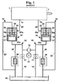
- an electro-hydraulic circuit of an actuator 1 for a motorcycle stand (shown in the following figures), operates an actuating member 7 movable between a first and a second position (which are also shown in the following figures).
- Actuator 1 which can be for example a cylinder/piston or a hydraulic motor, has a first mouth 1a for a liquid passage and a second mouth 1b also for a liquid passage, for moving the actuating member 7 between said positions.
- the first and second mouth 1a and 1b are associated to two different portions 10 and 10' of a hydraulic circuit.
- Each portion has a respective flow control valve 16 and 16' and is selectively fed of liquid in pressure by a suction duct 14, 14' that has an intake in a reservoir 40, through a check valve 11, 11'.
- the propulsion of liquid is carried out by a motor 12 that feeds a reversible pump 13, which can rotate in one of the two directions indicated by the arrows, and this way gives pressure to a branch 15 or 15'.
- the flow of liquid in pressure then, achieves selectively the flow control valve 16 or 16'.
- each valve 16 or 16' has an inlet 15a, 15'a that leads to a chamber 17 separated from another chamber 20 by a movable dividing wall 19 having holes 18.
- the movable dividing wall 19 is pushed back towards chamber 17 by a spring 23 and has a needle 24 suitable for engaging with a first outlet 21, stopping it.
- the chamber 20 has said first outlet 21 connected to a duct 22 (or 22') for discharging in the reservoir 40, and a second outlet 25a (or 25'a) that leads to a duct of a second outlet 25 (or 25') for delivering oil in pressure towards actuator 1.
- a safety valve 28, 28' is advantageously provided calibrated at a pressure higher than the maximum necessary for operating.
- the pump 12 delivers then oil in pressure to chamber 17 of valve 16 or 16' through either branch 15 or 15'.
- the discharging flow ceases immediately and automatically because the flow resistance to which the oil flow is subject when crossing the holes 18 of movable dividing wall 19 creates on the movable dividing wall same a force that, exceeding the reaction of spring 23, moves it towards chamber 20 so that the needle 24 can stop first outlet 21.
- the oil in pressure is necessarily delivered, through second mouth 25a or 25'a of chamber 20 and through duct 25 or 25', to actuator 1. While the actuating member 7 is moving, the flow resistance of the oil towards the chamber 9 of actuator 1, passing through the holes 18 of piston 19, continues to keep closed outlet 21 by needle 24, assisted also by the pressure of the oil that acts on the head of needle 24 same.
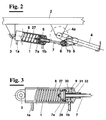
- a actuating cylinder 1 is connected at an end to the frame 2 of a motorcycle through a hinge 3, and at the other end to a stand 4.
- a fork lever 5 is integral, in the present example angled with respect to the plane of the stand, in which a cylindrical pivot 6 can rotate.
- the actuating cylinder 1 is associated to a stem 7 sliding in pivot 6.
- the stem 7 has at the end a piston 7a sliding in cylinder 1 and a head 7b of abutment against pivot 6.
- the piston 7a separates two chambers 8 and 9 within cylinder 1, in communication with respective mouths 1a and 1b for the passage of oil towards/away from a circuit shown hereinafter.
- a spring 27 is present that adapted to push piston 7a towards mouth 1b and then stem 7 out from cylinder 1.
- a plate 29 is present connected to a short tube 33 free to sealingly slide in the head 31 of cylinder 1 and in which in turn stem 7 sealingly slides. The motion of plate 29 towards head 31 is biased by a spring 30.
- head 7b abuts against pivot 6 when the pressure of the oil delivered in chamber 9 through mouth 1b, delivered by the pump 13 in the branch 10 of figure 5, moves the piston 7a with the stem 7 to it integral towards the left direction of figure 3, so that stem 7, through head 7b and pivot 6, pulls lever 5 up to full rotation of the stand with respect to frame 2.
- the spring 30, which may be provided, allows to maintain short tube in chamber 9 and then in correct position when the vehicle is running.
- a diagrammatical view of a stand arranged with a pushing actuator when lifting as of figure 7 has lever 5 opposite to stand 4 with respect to hinge 4b.
- an actuator is provided 1' that pushes instead of pulling when raising vehicle 2.
- the mechanics to cause the descent of the vehicle from the stand provides on stem 7 a pawl 7b and a pawl 7c. This way, when lifting stem 7 pushes the stand by pawl 7c, whereas when descending from the stand the stem 7 pulls the stand by pawl 7b for a small rotation up to the dead point of figure 9.
- the hydraulic circuit for this type of diagrammatical view can be that of figure 6, with reversing the ducts of mouths 1a and 1b.
- the movable dividing wall 19 has axial holes 18 that are partially closed by a unidirectional stopper 50 with a calibrated orifice from the side of the inlet, 15a or 15'a.
- the dividing wall 19 has, in this case, a protrusion 52 extending centrally towards inlet 15a or 15'a and about which a plate ring 53 is concentrically arranged that has a calibrated orifice 54.
- a spring 55 engages on the protrusion 52 and pushes the plate against the dividing wall 19, in order to close axial holes 18, except from the single passage allowed by the calibrated orifice 54.
- the holes 18 of valves 16 and 16' can be made of diameter larger than that shown in figure 1 or 6, allowing an exchange of oil directly from the first to the second mouth of passage, 1a and 1b, and vice-versa.
- the stem 7 of piston 1 when the stem 7 of piston 1 is pushed out, the oil coming from branch 15' enters valve 16' through mouth 15'a in the way above described, and must pass through calibrated orifice 54, for crossing dividing wall 19. Then, it achieves actuator 1 through the mouth 1a and pushes out stem 7. Owing to this action, the oil that exits through actuator 1 through mouth 1b achieves valve 16, crosses easily dividing wall 19 through holes 18 and exits through mouth 15a, feeding through branches 15 and 15' directly oil from valve 16'.
Landscapes
- Engineering & Computer Science (AREA)
- Mechanical Engineering (AREA)
- Fluid-Pressure Circuits (AREA)
- Actuator (AREA)
Applications Claiming Priority (2)
| Application Number | Priority Date | Filing Date | Title |
|---|---|---|---|
| ITPI20030069 | 2003-09-17 | ||
| IT000069A ITPI20030069A1 (it) | 2003-09-17 | 2003-09-17 | Circuito elettroidraulico semplificato per un attuatore |
Publications (2)
| Publication Number | Publication Date |
|---|---|
| EP1516805A2 true EP1516805A2 (fr) | 2005-03-23 |
| EP1516805A3 EP1516805A3 (fr) | 2007-10-17 |
Family
ID=30012927
Family Applications (1)
| Application Number | Title | Priority Date | Filing Date |
|---|---|---|---|
| EP04022254A Withdrawn EP1516805A3 (fr) | 2003-09-17 | 2004-09-17 | Dispositif hydraulique actionneur pour la mise en oeuvre des béquilles de motocyclettes. |
Country Status (2)
| Country | Link |
|---|---|
| EP (1) | EP1516805A3 (fr) |
| IT (1) | ITPI20030069A1 (fr) |
Cited By (4)
| Publication number | Priority date | Publication date | Assignee | Title |
|---|---|---|---|---|
| ITVR20110181A1 (it) * | 2011-09-19 | 2013-03-20 | Mario Bottacini | Dispositivo a cavalletto per motocicli |
| CN105438319A (zh) * | 2015-12-16 | 2016-03-30 | 浙江大学 | 半自动化控制电动车支撑脚架及其使用方法 |
| CN108860375A (zh) * | 2018-07-18 | 2018-11-23 | 海智博纳科技(北京)有限公司 | 一种具有失效保护功能的电动车起落架 |
| CN109210027A (zh) * | 2017-07-05 | 2019-01-15 | 通用汽车环球科技运作有限责任公司 | 可在正向和反向正排量泵旋转下实现单向流动的液压回路 |
Families Citing this family (1)
| Publication number | Priority date | Publication date | Assignee | Title |
|---|---|---|---|---|
| CN108556969A (zh) * | 2018-04-13 | 2018-09-21 | 昆明理工大学 | 一种自动车梯装置 |
Citations (2)
| Publication number | Priority date | Publication date | Assignee | Title |
|---|---|---|---|---|
| WO1999047407A1 (fr) | 1998-03-18 | 1999-09-23 | Marco Doveri | Dispositif actionneur pour la mise en oeuvre des bequilles de motocyclettes, et soupape hydraulique a declenchement automatique |
| EP1254829A1 (fr) | 2001-04-30 | 2002-11-06 | Marco Doveri | Dispositif actionneur pour la mise en oeuvre des béquilles de motocyclette |
Family Cites Families (4)
| Publication number | Priority date | Publication date | Assignee | Title |
|---|---|---|---|---|
| JPS6094824A (ja) * | 1983-10-28 | 1985-05-28 | Mitsubishi Electric Corp | 自動車用蓄勢装置 |
| FR2771368B1 (fr) * | 1997-11-26 | 1999-12-24 | Jean Pierre Leroy | Bequille hydraulique pour moto |
| US6006849A (en) * | 1998-02-11 | 1999-12-28 | Watkins; Jonathan | Single-track vehicle with foot pedal feedback and inertial force limiters |
| FR2786749B1 (fr) * | 1998-12-08 | 2001-02-16 | Pierre Gillet | Vehicule de type monotrace a roues stabilisatrices escamotables asservies a la vitesse |
-
2003
- 2003-09-17 IT IT000069A patent/ITPI20030069A1/it unknown
-
2004
- 2004-09-17 EP EP04022254A patent/EP1516805A3/fr not_active Withdrawn
Patent Citations (2)
| Publication number | Priority date | Publication date | Assignee | Title |
|---|---|---|---|---|
| WO1999047407A1 (fr) | 1998-03-18 | 1999-09-23 | Marco Doveri | Dispositif actionneur pour la mise en oeuvre des bequilles de motocyclettes, et soupape hydraulique a declenchement automatique |
| EP1254829A1 (fr) | 2001-04-30 | 2002-11-06 | Marco Doveri | Dispositif actionneur pour la mise en oeuvre des béquilles de motocyclette |
Cited By (5)
| Publication number | Priority date | Publication date | Assignee | Title |
|---|---|---|---|---|
| ITVR20110181A1 (it) * | 2011-09-19 | 2013-03-20 | Mario Bottacini | Dispositivo a cavalletto per motocicli |
| CN105438319A (zh) * | 2015-12-16 | 2016-03-30 | 浙江大学 | 半自动化控制电动车支撑脚架及其使用方法 |
| CN105438319B (zh) * | 2015-12-16 | 2017-10-31 | 浙江大学 | 半自动化控制电动车支撑脚架及其使用方法 |
| CN109210027A (zh) * | 2017-07-05 | 2019-01-15 | 通用汽车环球科技运作有限责任公司 | 可在正向和反向正排量泵旋转下实现单向流动的液压回路 |
| CN108860375A (zh) * | 2018-07-18 | 2018-11-23 | 海智博纳科技(北京)有限公司 | 一种具有失效保护功能的电动车起落架 |
Also Published As
| Publication number | Publication date |
|---|---|
| ITPI20030069A1 (it) | 2005-03-18 |
| EP1516805A3 (fr) | 2007-10-17 |
| ITPI20030069A0 (it) | 2003-09-17 |
Similar Documents
| Publication | Publication Date | Title |
|---|---|---|
| US6701823B2 (en) | Method and device for controlling a lift cylinder, especially of working machines | |
| CN102102689B (zh) | 液控单向阀 | |
| US9605801B2 (en) | Lubricating grease return valve | |
| CN100357614C (zh) | 用于控制旋转臂的方法以及控制旋转臂的装置 | |
| EP1516805A2 (fr) | Dispositif hydraulique actionneur pour la mise en oeuvre des béquilles de motocyclettes. | |
| CA2639246A1 (fr) | Verin hydraulique a plusieurs etages | |
| MXPA06006671A (es) | Mecanismo de apertura para un operador de puerta giratorio. | |
| CN118561210A (zh) | 一种叉车全自由门架液压系统 | |
| JP2004507684A (ja) | 緊急操作手段付パイロットソレノイド制御バルブ | |
| PL166561B1 (pl) | Zespól do sterowania ruchem w góre i w dól hydraulicznego podnosnika PL | |
| US6679054B2 (en) | Electro-hydraulic actuator of a motorcycle stand | |
| US4460152A (en) | Hand pump with automatic lock-out | |
| US6168390B1 (en) | Dosing pump for dosed liquid conveyance | |
| US6715282B1 (en) | Actuator device, in particular for operating the stand of motorcycles, and automatically releasable hydraulic valve | |
| US10006555B2 (en) | Fluid discharge valve | |
| KR20080020970A (ko) | 밸브 장치 | |
| US5235896A (en) | Hydraulic cylinder/piston mechanism | |
| CN202001415U (zh) | 液控单向阀 | |
| CN1406689A (zh) | 连铸大包滑动水口液压传动系统 | |
| TW201139261A (en) | Drive unit for a hoisting apparatus driven by a pressure medium | |
| JPH0730922Y2 (ja) | ポンプ装置におけるエンジンの回転制御装置 | |
| KR200264481Y1 (ko) | 유압펌프의 덤프시스템 | |
| GB2471941A (en) | Hydraulic pump comprising multiple coaxial pistons | |
| JPS5813197A (ja) | 可動翼ポンプ | |
| KR950014364B1 (ko) | 적공 제동 자동 제어 장치 |
Legal Events
| Date | Code | Title | Description |
|---|---|---|---|
| PUAI | Public reference made under article 153(3) epc to a published international application that has entered the european phase |
Free format text: ORIGINAL CODE: 0009012 |
|
| AK | Designated contracting states |
Kind code of ref document: A2 Designated state(s): AT BE BG CH CY CZ DE DK EE ES FI FR GB GR HU IE IT LI LU MC NL PL PT RO SE SI SK TR |
|
| AX | Request for extension of the european patent |
Extension state: AL HR LT LV MK |
|
| PUAL | Search report despatched |
Free format text: ORIGINAL CODE: 0009013 |
|
| AK | Designated contracting states |
Kind code of ref document: A3 Designated state(s): AT BE BG CH CY CZ DE DK EE ES FI FR GB GR HU IE IT LI LU MC NL PL PT RO SE SI SK TR |
|
| AX | Request for extension of the european patent |
Extension state: AL HR LT LV MK |
|
| 17P | Request for examination filed |
Effective date: 20080331 |
|
| AKX | Designation fees paid |
Designated state(s): AT BE BG CH CY CZ DE DK EE ES FI FR GB GR HU IE IT LI LU MC NL PL PT RO SE SI SK TR |
|
| 17Q | First examination report despatched |
Effective date: 20090107 |
|
| R17C | First examination report despatched (corrected) |
Effective date: 20090113 |
|
| GRAP | Despatch of communication of intention to grant a patent |
Free format text: ORIGINAL CODE: EPIDOSNIGR1 |
|
| STAA | Information on the status of an ep patent application or granted ep patent |
Free format text: STATUS: THE APPLICATION IS DEEMED TO BE WITHDRAWN |
|
| 18D | Application deemed to be withdrawn |
Effective date: 20120801 |