EP1520975B1 - Filtre à air dans un système d'admission pour un moteur à combustion interne - Google Patents
Filtre à air dans un système d'admission pour un moteur à combustion interne Download PDFInfo
- Publication number
- EP1520975B1 EP1520975B1 EP04104750A EP04104750A EP1520975B1 EP 1520975 B1 EP1520975 B1 EP 1520975B1 EP 04104750 A EP04104750 A EP 04104750A EP 04104750 A EP04104750 A EP 04104750A EP 1520975 B1 EP1520975 B1 EP 1520975B1
- Authority
- EP
- European Patent Office
- Prior art keywords
- housing
- filter element
- functional
- air
- cassette
- Prior art date
- Legal status (The legal status is an assumption and is not a legal conclusion. Google has not performed a legal analysis and makes no representation as to the accuracy of the status listed.)
- Expired - Lifetime
Links
- 238000002485 combustion reaction Methods 0.000 title claims description 5
- 238000007789 sealing Methods 0.000 claims description 31
- 238000000034 method Methods 0.000 claims description 5
- 238000003780 insertion Methods 0.000 claims description 4
- 230000037431 insertion Effects 0.000 claims description 4
- 238000012423 maintenance Methods 0.000 claims description 3
- 230000006835 compression Effects 0.000 claims 1
- 238000007906 compression Methods 0.000 claims 1
- 210000000078 claw Anatomy 0.000 abstract description 2
- 239000011324 bead Substances 0.000 description 10
- 230000000694 effects Effects 0.000 description 4
- 238000009434 installation Methods 0.000 description 3
- 239000000463 material Substances 0.000 description 3
- 238000001816 cooling Methods 0.000 description 2
- 238000004519 manufacturing process Methods 0.000 description 2
- 239000004952 Polyamide Substances 0.000 description 1
- 239000004743 Polypropylene Substances 0.000 description 1
- 230000009286 beneficial effect Effects 0.000 description 1
- 238000011109 contamination Methods 0.000 description 1
- 238000011161 development Methods 0.000 description 1
- 238000001914 filtration Methods 0.000 description 1
- 230000010354 integration Effects 0.000 description 1
- 229910052751 metal Inorganic materials 0.000 description 1
- 239000002184 metal Substances 0.000 description 1
- 150000002739 metals Chemical class 0.000 description 1
- 239000004033 plastic Substances 0.000 description 1
- 229920003023 plastic Polymers 0.000 description 1
- 229920002647 polyamide Polymers 0.000 description 1
- -1 polypropylene Polymers 0.000 description 1
- 229920001155 polypropylene Polymers 0.000 description 1
- 238000003825 pressing Methods 0.000 description 1
- 238000012546 transfer Methods 0.000 description 1
Images
Classifications
-
- F—MECHANICAL ENGINEERING; LIGHTING; HEATING; WEAPONS; BLASTING
- F02—COMBUSTION ENGINES; HOT-GAS OR COMBUSTION-PRODUCT ENGINE PLANTS
- F02M—SUPPLYING COMBUSTION ENGINES IN GENERAL WITH COMBUSTIBLE MIXTURES OR CONSTITUENTS THEREOF
- F02M35/00—Combustion-air cleaners, air intakes, intake silencers, or induction systems specially adapted for, or arranged on, internal-combustion engines
- F02M35/02—Air cleaners
- F02M35/024—Air cleaners using filters, e.g. moistened
-
- B—PERFORMING OPERATIONS; TRANSPORTING
- B01—PHYSICAL OR CHEMICAL PROCESSES OR APPARATUS IN GENERAL
- B01D—SEPARATION
- B01D46/00—Filters or filtering processes specially modified for separating dispersed particles from gases or vapours
- B01D46/0002—Casings; Housings; Frame constructions
- B01D46/0004—Details of removable closures, lids, caps or filter heads
-
- B—PERFORMING OPERATIONS; TRANSPORTING
- B01—PHYSICAL OR CHEMICAL PROCESSES OR APPARATUS IN GENERAL
- B01D—SEPARATION
- B01D46/00—Filters or filtering processes specially modified for separating dispersed particles from gases or vapours
- B01D46/0002—Casings; Housings; Frame constructions
- B01D46/0005—Mounting of filtering elements within casings, housings or frames
-
- B—PERFORMING OPERATIONS; TRANSPORTING
- B01—PHYSICAL OR CHEMICAL PROCESSES OR APPARATUS IN GENERAL
- B01D—SEPARATION
- B01D46/00—Filters or filtering processes specially modified for separating dispersed particles from gases or vapours
- B01D46/10—Particle separators, e.g. dust precipitators, using filter plates, sheets or pads having plane surfaces
-
- B—PERFORMING OPERATIONS; TRANSPORTING
- B01—PHYSICAL OR CHEMICAL PROCESSES OR APPARATUS IN GENERAL
- B01D—SEPARATION
- B01D46/00—Filters or filtering processes specially modified for separating dispersed particles from gases or vapours
- B01D46/42—Auxiliary equipment or operation thereof
-
- B—PERFORMING OPERATIONS; TRANSPORTING
- B01—PHYSICAL OR CHEMICAL PROCESSES OR APPARATUS IN GENERAL
- B01D—SEPARATION
- B01D46/00—Filters or filtering processes specially modified for separating dispersed particles from gases or vapours
- B01D46/52—Particle separators, e.g. dust precipitators, using filters embodying folded corrugated or wound sheet material
- B01D46/521—Particle separators, e.g. dust precipitators, using filters embodying folded corrugated or wound sheet material using folded, pleated material
Definitions
- the invention relates to an air filter system referred to in the preamble of claim 1. Art Furthermore, the invention relates to a method according to claim 10 for introducing an air filter element in an air filter system according to claim 1.
- the controlled air flow on the suction side of the internal combustion engine is used to cool the electronic control units.
- the electronic control units are attached to the air filter such that a heat-transferring surface is directly adjacent to the air flow.
- an air filter system which consists of two chambers.
- the two chambers communicate through two channels which communicate at the adjacent wall of the chambers.
- a closure flap for the control unit chamber and a lid for the chamber of the filter element are required, wherein a clean air outlet is arranged on the lid of the filter element.
- the flap closes the chamber of the electronic control unit and serves at the same time to fix it. No seal is arranged between the chamber and the closure flap, so that part of the raw air flows over the surface of the electronic control unit to the filter element.
- the outside air is sucked in through the unfiltered air inlet present at the filter chamber and flows due to the different pressure conditions, partly through the connection channels of the chamber of the electronic control unit.
- two air flows are generated, which cool the electronic control unit.
- the disadvantage here is the high manufacturing complexity and the material requirements, which is necessary by the arrangement of two housing chambers.
- Another disadvantage is the high number of necessary items, since each housing is closed individually becomes.
- the control unit is installed on the raw air side of the air filter system, whereby pollution is expected.
- the object of the invention is to avoid the above-mentioned disadvantages and to form an air filter system with low material costs and few individual parts, which is easy and reliable to assemble and allows the integration of an electronic control unit.
- the air filter system according to the invention for an internal combustion engine, in particular a vehicle has a housing in which air flows in via a unfiltered air inlet, a clean air outlet through which the air flows out and an interposed filter element through which the air stream flows.
- the housing has an additional functional opening and a contour within the housing for receiving the filter element.
- the function opening forms an access to the inside of the housing, whereby the filter element can be replaced.
- the filter element is preferably a flat filter element and has an elastic sealing bead.
- the sealing bead corresponds to a sealing surface arranged inside the filter housing and establishes a tight connection between a raw air side and a clean air side.
- a functional element which is designed in particular as an electronic control unit for controlling an internal combustion engine, serves to close the functional opening.
- the plate-shaped electronic control unit has a side that is located outside of the filter housing and to which the necessary electronic connections are attached. On the inside of the housing side, the surface is designed so that an optimized heat transfer takes place. This is z. B. by the arrangement of cooling fins, which increase the surface reaches.
- the electronic control unit thus forms the lid of the air filter housing and adjacent to the inner side of the air flow, whereby cooling of the electronic control unit is achieved. If the electronic control unit is dismantled, the access to the filter element located in the housing is free through the function opening and the filter element can be exchanged.
- the cassette encloses the mechanically labile filter element on the side surfaces and stabilizes the elastic sealing bead. This can be achieved in that the sealing bead projects beyond the filter element on the circumference, whereby a bearing surface for the cassette is formed. As a result, the cassette can press the sealing bead defined on a sealing surface of the housing. Thus, the cassette forms a carrier function of the filter element.
- the cassette can be fixed within the housing by means of screw, snap, or clip connections or clamped by cams, springs or insertion bevels. As materials are preferably plastics such as polyamide or polypropylene in question, but it can also be used metals.
- An advantageous development of the invention is the arrangement of a contour within the air filter housing, which corresponds to the filter element.
- the contour can be formed for example by cams or webs, which are made in one piece with the housing and to which the cassette is supported during insertion or in the installed state.
- the contour can also produce a pre-attachment of the cassette in such a way that the cassette is fixed in the filter housing, but still no tight connection is made.
- the final attachment may be at a later date z. B. done with the assembly of the control unit.
- the ability to introduce the cassette by means of sliding elements mounted on inclined or stepped to the sealing surface extending rails and clamp to the sealing surface. As a result, the introduction and the tension of the element are facilitated.
- a further embodiment for fastening the cassette or the filter element allows the attachment of a pivot axis on the filter element or on the cassette.
- the pivot axis is received in an opposite pivoting contour.
- the pivot axis can be formed for example by a cylindrical cam and the pivot contour by a claw-shaped paragraph.
- the connection between the pivot axis and pivot contour can, for. B. by a snap be executed restrained.
- the attachment of the filter element or the cassette in the housing by a fastener can be a screw, clip or latching connection.
- a fastener can be fixed by pressing against the sealing surface by a relative to the pivot contour attached hook, which finds a receptacle in the housing, the filter element.
- the fixation may be final or reinforced at a later date, for example, by mounting the control unit. Due to the pivotal attachment, a high pressure on the sealing surfaces can be exerted due to the leverage effect, which leads to a reliable sealing effect.
- a further advantageous embodiment is the attachment of the electronic control unit on the housing.
- the electronic control unit By arranged on one side of the electronic control unit mounting axis, which finds a pivotal receptacle on the housing, the electronic control unit is introduced on one side and can be pivoted on the opposite side and fixed with fasteners.
- the electronic control unit is introduced on one side and can be pivoted on the opposite side and fixed with fasteners.
- pressure elements are mounted on the electronic control device, which in the form of cams, webs or jaws transmit a pressure to the filter element during assembly of the electronic control device and thus produce the seal between the filter element and the housing.
- cams are suitable as contours that can be attached to the electronic control unit or to the filter element or the cassette.
- the pressure body of the electronic control unit and the corresponding contours of the cassette can be tuned in their geometry such that, taking into account all possible manufacturing and assembly tolerances always results in an overlap of the contact points.
- the pivoting range of the cassette can be limited. This will ensure that the cams of the electronic control unit always find a stop in the cassette when swung into the housing. Since the filter element rests only on the sealing surface, when it is in matching position to the housing, thus a faulty mounting of the cassette is excluded.
- the systems facilitate the insertion of the cassette into the housing.
- An advantageous seal between electronic control unit and air filter housing is the arrangement of a circumferential seal in a groove which encloses the functional opening of the electronic control unit.
- the seal can be delivered pre-assembled with the air filter system and also facilitates the installation of the electronic control unit.
- the arrangement of the electronic control unit on a side facing the air flow is advantageous. This arrangement is determined by tuning the Lucas Equipmentsgeometrie and allows optimal heat exchange between the electronic control unit and air flow.
- the inventive method for introducing a filter element into the inside of an air filter housing by a functional opening is characterized in that the function opening simultaneously allows the inclusion of an electronic control unit, which is cooled by the voltage applied to the air filter housing air flow.
- the filter element is introduced through the functional opening with the side on which there is an attached pivot axis in the air filter housing.
- the pivot axis finds a receptacle in the filter housing.
- the filter element is pressed against the sealing surface and fixed by a detent.
- the electronic control unit is now pivoted towards the housing and fixed with the provided fasteners.
- the filter element is pressed by clamping cam to the sealing surface to the air filter housing.
- the electronic control unit is pressed against the outer sealing surface to the housing. Be beneficial both in one operation braced the electronic control unit and the filter element with the respective sealing surface. Furthermore, no additional closure member needs to be attached to the air filter housing.
- An advantageous effect of the method is achieved in that the filter element mounted in the air filter housing is fixed by a fastening element.
- the attachment of a hook on the cassette offers, which hooks when pressed in an edge provided on the housing, whereby the filter element is pressed against the intended sealing contour on the housing.
- the filter element is fixed in position and can be transported to other locations.
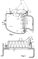
- FIG. 1 shows an air filter system with a housing 1, a Rohlufteinlass 2 and a clean air outlet 3.
- a filter element 4 is arranged, which is introduced into a cassette 5 and is fixed by an electronic control unit 6.
- a pivot axis 7 is present, which is accommodated on a pivoting contour 8.
- the pivoting contour 8 is attached to the housing 1.
- the cassette 5 On the side opposite the pivoting contour 8 side, the cassette 5 has a nose 5a.
- the housing 1 has a functional opening 11, through which the filter element 4 with the cassette 5 is introduced into the housing 1.
- the housing 1 has installations 18 which project into the interior of the housing 1.
- the systems 18 are arranged on both sides of the functional opening 11, wherein system nose 5 a of the cassette 5 in unstressed state, for. B. during transport of the pre-assembled filter element 4, abut the plants 18. In this case, the filter element 4 is not yet in the required position for filtration.
- the filter element 4 is enclosed by the frame of the cassette 5 and pressed with an edge 5b of the cassette 5 via a sealing bead 10 on a sealing surface 1a of the housing 1.
- the sealing bead 10 is arranged on the filter element 4 or the cassette 5.
- the sealing bead 10 can also be arranged on the housing 1.
- the electronic control unit 6 mounted in the functional opening 11 is received in a fastening axis 12 by claws 13 attached to the housing 1 and fixed to the housing 1 on the opposite side by means of a screw connection 14.
- a circumferential seal 15 is arranged, which ensures the seal between the housing 1 and the electronic control unit 6.
- FIG. 2 shows the filter element 4, which is fastened by a latching connection between the cassette 5 and the housing 1.
- a hook bracket 16 is arranged on the cassette 5, which corresponds to a latching element 17 of the housing 1.
- the hook bracket 16 and locking element 17 are flexurally elastic and form a detachable locking connection.
- the locking element 17 may also be formed by a, in the direction of hook bracket 16 projecting housing edge (not shown).
- the latching connection shown is suitable, for example, as a transport lock of the preassembled in the housing 1 filter element 4. The final sealing of the connection takes place by the pivoting of the control unit 6 according to FIG. 1 and thereby pressed against the housing 1 sealing bead 10th
Landscapes
- Chemical & Material Sciences (AREA)
- Chemical Kinetics & Catalysis (AREA)
- Engineering & Computer Science (AREA)
- Combustion & Propulsion (AREA)
- Mechanical Engineering (AREA)
- General Engineering & Computer Science (AREA)
- Filtering Of Dispersed Particles In Gases (AREA)
Claims (10)
- Installation de filtration d'air pour un moteur à combustion interne, présentant un carter, une entrée d'air brut, une sortie d'air pur, un élément filtrant disposé de façon étanche entre l'entrée d'air brut et la sortie d'air pur et un orifice fonctionnel supplémentaire dans le carter, l'élément filtrant pouvant être introduit dans le carter par l'orifice fonctionnel, caractérisé en ce que l'orifice fonctionnel du carter peut être obturé par un élément fonctionnel, l'élément fonctionnel étant un appareil de commande électronique.
- Installation de filtration d'air selon la revendication 1, caractérisée en ce que l'élément filtrant est disposé dans une cassette qui peut être introduite dans le carter par l'orifice fonctionnel.
- Installation de filtration d'air selon l'une des revendications précédentes, caractérisée en ce que le carter présente un contour par lequel l'élément filtrant est positionné.
- Installation de filtration d'air selon l'une des revendications précédentes, caractérisée en ce que l'élément filtrant ou la cassette peut être monté(e) d'un côté de manière pivotante.
- Installation de filtration d'air selon l'une des revendications précédentes, caractérisée en ce que l'élément filtrant ou la cassette dans le carter est relié de manière amovible au carter par au moins un élément de fixation.
- Installation de filtration d'air selon l'une des revendications précédentes, caractérisée en ce que, d'un côté, l'élément fonctionnel est monté de manière pivotante et, du côté opposé, est relié de manière amovible au carter.
- Installation de filtration d'air selon l'une des revendications précédentes, caractérisée en ce que des éléments de pression sont montés sur l'élément fonctionnel et/ou sur la cassette ou sur l'élément filtrant, lesquels exercent une pression de contact sur l'élément de pression lors de la fixation de l'élément fonctionnel, ce qui génère une compression entre le carter et l'élément filtrant.
- Installation de filtration d'air selon l'une des revendications précédentes, caractérisée en ce qu'un joint circulaire est disposé entre le carter et l'élément fonctionnel.
- Installation de filtration d'air selon l'une des revendications précédentes, caractérisée en ce que l'appareil de commande électronique sur la face intérieure du carter est disposé d'un côté orienté vers le flux d'air.
- Procédure d'entretien d'une installation de filtration d'air selon les revendications 1 à 9, comprenant au moins les opérations suivantes :- ouverture de l'orifice fonctionnel par retrait de l'élément fonctionnel,- retrait de l'élément fonctionnel du carter à travers l'orifice fonctionnel,- introduction du nouvel élément filtrant à travers l'orifice fonctionnel,- fermeture de l'orifice fonctionnel par l'élément fonctionnel.
Applications Claiming Priority (2)
| Application Number | Priority Date | Filing Date | Title |
|---|---|---|---|
| DE10345684A DE10345684A1 (de) | 2003-10-01 | 2003-10-01 | Luftfilteranlage im Ansaugtrakt einer Brennkraftmaschine |
| DE10345684 | 2003-10-01 |
Publications (3)
| Publication Number | Publication Date |
|---|---|
| EP1520975A2 EP1520975A2 (fr) | 2005-04-06 |
| EP1520975A3 EP1520975A3 (fr) | 2010-03-10 |
| EP1520975B1 true EP1520975B1 (fr) | 2011-11-02 |
Family
ID=34306180
Family Applications (1)
| Application Number | Title | Priority Date | Filing Date |
|---|---|---|---|
| EP04104750A Expired - Lifetime EP1520975B1 (fr) | 2003-10-01 | 2004-09-29 | Filtre à air dans un système d'admission pour un moteur à combustion interne |
Country Status (4)
| Country | Link |
|---|---|
| EP (1) | EP1520975B1 (fr) |
| AT (1) | ATE531925T1 (fr) |
| DE (1) | DE10345684A1 (fr) |
| ES (1) | ES2376384T3 (fr) |
Families Citing this family (5)
| Publication number | Priority date | Publication date | Assignee | Title |
|---|---|---|---|---|
| DE102005031501B4 (de) | 2005-07-06 | 2021-12-09 | Andreas Stihl Ag & Co. Kg | Luftfilter |
| DE202008011714U1 (de) | 2008-09-03 | 2010-01-28 | Mann+Hummel Gmbh | Luftfiltersystem für eine Brennkraftmaschine |
| DE102014015760B4 (de) * | 2014-10-27 | 2016-07-14 | Mann + Hummel Gmbh | Filtergehäuse mit Hebelelement |
| US20200072169A1 (en) | 2018-08-28 | 2020-03-05 | Parker-Hannifin Corporation | Non-cylindrical filter element and side entry air cleaner incorporating the same |
| US20220274041A1 (en) | 2021-02-26 | 2022-09-01 | Parker-Hannifin Corporation | Side entry wave seal air cleaner |
Family Cites Families (8)
| Publication number | Priority date | Publication date | Assignee | Title |
|---|---|---|---|---|
| CA1043899A (fr) * | 1975-05-30 | 1978-12-05 | Ivor W. Carter | Dispositif de montage de plaquettes de circuits electroniques sur le filtre d'air d'un moteur |
| DE3338653A1 (de) * | 1983-10-25 | 1985-05-02 | Volkswagenwerk Ag, 3180 Wolfsburg | Luftfilter fuer eine brennkraftmaschine |
| JPH04203437A (ja) * | 1990-11-30 | 1992-07-24 | Hitachi Ltd | 自動車用制御機器 |
| JP3473642B2 (ja) * | 1994-09-20 | 2003-12-08 | 株式会社デンソー | 燃料噴射装置 |
| JPH08210201A (ja) * | 1995-02-06 | 1996-08-20 | Kansei Corp | 電装部品内蔵のエアクリーナボックス |
| DE19534036A1 (de) * | 1995-09-14 | 1997-03-20 | Mann & Hummel Filter | Luftfilter |
| GB9823556D0 (en) * | 1998-10-28 | 1998-12-23 | Rover Group | A motor vehicle |
| JP2002188535A (ja) * | 2000-12-18 | 2002-07-05 | Auto Network Gijutsu Kenkyusho:Kk | エアクリーナ装置 |
-
2003
- 2003-10-01 DE DE10345684A patent/DE10345684A1/de not_active Withdrawn
-
2004
- 2004-09-29 EP EP04104750A patent/EP1520975B1/fr not_active Expired - Lifetime
- 2004-09-29 AT AT04104750T patent/ATE531925T1/de active
- 2004-09-29 ES ES04104750T patent/ES2376384T3/es not_active Expired - Lifetime
Also Published As
| Publication number | Publication date |
|---|---|
| EP1520975A3 (fr) | 2010-03-10 |
| EP1520975A2 (fr) | 2005-04-06 |
| ES2376384T3 (es) | 2012-03-13 |
| DE10345684A1 (de) | 2005-04-21 |
| ATE531925T1 (de) | 2011-11-15 |
Similar Documents
| Publication | Publication Date | Title |
|---|---|---|
| EP2051890B1 (fr) | Dispositif d'alimentation en air comprimé | |
| EP3228376B1 (fr) | Module de filtration comprenant un élément de filtre et un cadre de fixation et installation de filtre à air comprenant un module de filtration | |
| DE102014006852B4 (de) | Hohlfilterelement, Filtergehäuse und Filter | |
| EP2509699B1 (fr) | Elément filtrant et filtre à air | |
| EP2051892B1 (fr) | Dispositif d'alimentation en air comprimé pour un véhicule utilitaire et cartouche de dessiccateur | |
| EP1818533A2 (fr) | Système de sécurité pour un piège d'hydrocarbure | |
| EP2675546A1 (fr) | Système de filtre à air et élément filtrant | |
| EP2582444B1 (fr) | Cartouche filtrante | |
| DE102008036913B3 (de) | Luftfiltersystem | |
| DE2816526A1 (de) | Oelfilter, insbesondere fuer dieseloel, und verfahren zu seiner herstellung | |
| WO2016146250A1 (fr) | Dispositif filtrant et élément filtrant, en particulier pour un véhicule à moteur | |
| DE102016004575A1 (de) | Haube eines Multi-Zyklonblocks eines Luftreinigers und Luftreiniger | |
| DE102015209681A1 (de) | Abgasbehandlungseinrichtung mit austauschbarem Einsatz | |
| DE102009020060B4 (de) | Fahrzeugklimaanlagenbaugruppe und Verfahren zum Zusammenbau | |
| EP2888023B1 (fr) | Dispositif de filtration, en particulier pour la filtration de gaz | |
| DE102018119220B3 (de) | Filterelement zur Filtration und Entfeuchtung eines Gases und Filtereinrichtung | |
| DE19849089A1 (de) | Filter, insbesondere für die Ansaugluft einer Brennkraftmaschine | |
| EP1870570B1 (fr) | Dispositif comprenant un échangeur de chaleur et un filtre pour liquide | |
| EP1520975A2 (fr) | Filtre a air dans un systeme d'admission pour un moteur a combustion interne | |
| EP2305992A2 (fr) | Filtre à air pour moteur à combustion interne | |
| EP4139023A1 (fr) | Élément filtrant pour un dispositif de filtre à air dans un véhicule à moteur et dispositif de filtre à air | |
| DE102005040607A1 (de) | Anordnung zur Befestigung eines Wärmeübertragers an einem anderen | |
| DE102008027847A1 (de) | Luftfilter, insbesondere für die Ansaugluft einer Brennkraftmaschine | |
| DE10059911A1 (de) | Wärmetauscheranschluß | |
| DE3924676C2 (fr) |
Legal Events
| Date | Code | Title | Description |
|---|---|---|---|
| PUAI | Public reference made under article 153(3) epc to a published international application that has entered the european phase |
Free format text: ORIGINAL CODE: 0009012 |
|
| AK | Designated contracting states |
Kind code of ref document: A2 Designated state(s): AT BE BG CH CY CZ DE DK EE ES FI FR GB GR HU IE IT LI LU MC NL PL PT RO SE SI SK TR |
|
| AX | Request for extension of the european patent |
Extension state: AL HR LT LV MK |
|
| PUAL | Search report despatched |
Free format text: ORIGINAL CODE: 0009013 |
|
| AK | Designated contracting states |
Kind code of ref document: A3 Designated state(s): AT BE BG CH CY CZ DE DK EE ES FI FR GB GR HU IE IT LI LU MC NL PL PT RO SE SI SK TR |
|
| AX | Request for extension of the european patent |
Extension state: AL HR LT LV MK |
|
| 17P | Request for examination filed |
Effective date: 20100414 |
|
| AKX | Designation fees paid |
Designated state(s): AT BE BG CH CY CZ DE DK EE ES FI FR GB GR HU IE IT LI LU MC NL PL PT RO SE SI SK TR |
|
| RIC1 | Information provided on ipc code assigned before grant |
Ipc: F02M 35/024 20060101AFI20110315BHEP |
|
| GRAP | Despatch of communication of intention to grant a patent |
Free format text: ORIGINAL CODE: EPIDOSNIGR1 |
|
| GRAS | Grant fee paid |
Free format text: ORIGINAL CODE: EPIDOSNIGR3 |
|
| GRAA | (expected) grant |
Free format text: ORIGINAL CODE: 0009210 |
|
| AK | Designated contracting states |
Kind code of ref document: B1 Designated state(s): AT BE BG CH CY CZ DE DK EE ES FI FR GB GR HU IE IT LI LU MC NL PL PT RO SE SI SK TR |
|
| REG | Reference to a national code |
Ref country code: GB Ref legal event code: FG4D Free format text: NOT ENGLISH |
|
| REG | Reference to a national code |
Ref country code: CH Ref legal event code: EP |
|
| REG | Reference to a national code |
Ref country code: IE Ref legal event code: FG4D |
|
| REG | Reference to a national code |
Ref country code: DE Ref legal event code: R096 Ref document number: 502004013024 Country of ref document: DE Effective date: 20120112 |
|
| REG | Reference to a national code |
Ref country code: NL Ref legal event code: VDEP Effective date: 20111102 |
|
| REG | Reference to a national code |
Ref country code: ES Ref legal event code: FG2A Ref document number: 2376384 Country of ref document: ES Kind code of ref document: T3 Effective date: 20120313 |
|
| PG25 | Lapsed in a contracting state [announced via postgrant information from national office to epo] |
Ref country code: SE Free format text: LAPSE BECAUSE OF FAILURE TO SUBMIT A TRANSLATION OF THE DESCRIPTION OR TO PAY THE FEE WITHIN THE PRESCRIBED TIME-LIMIT Effective date: 20111102 Ref country code: NL Free format text: LAPSE BECAUSE OF FAILURE TO SUBMIT A TRANSLATION OF THE DESCRIPTION OR TO PAY THE FEE WITHIN THE PRESCRIBED TIME-LIMIT Effective date: 20111102 Ref country code: GR Free format text: LAPSE BECAUSE OF FAILURE TO SUBMIT A TRANSLATION OF THE DESCRIPTION OR TO PAY THE FEE WITHIN THE PRESCRIBED TIME-LIMIT Effective date: 20120203 Ref country code: PL Free format text: LAPSE BECAUSE OF FAILURE TO SUBMIT A TRANSLATION OF THE DESCRIPTION OR TO PAY THE FEE WITHIN THE PRESCRIBED TIME-LIMIT Effective date: 20111102 Ref country code: SI Free format text: LAPSE BECAUSE OF FAILURE TO SUBMIT A TRANSLATION OF THE DESCRIPTION OR TO PAY THE FEE WITHIN THE PRESCRIBED TIME-LIMIT Effective date: 20111102 Ref country code: PT Free format text: LAPSE BECAUSE OF FAILURE TO SUBMIT A TRANSLATION OF THE DESCRIPTION OR TO PAY THE FEE WITHIN THE PRESCRIBED TIME-LIMIT Effective date: 20120302 |
|
| REG | Reference to a national code |
Ref country code: IE Ref legal event code: FD4D |
|
| PG25 | Lapsed in a contracting state [announced via postgrant information from national office to epo] |
Ref country code: CY Free format text: LAPSE BECAUSE OF FAILURE TO SUBMIT A TRANSLATION OF THE DESCRIPTION OR TO PAY THE FEE WITHIN THE PRESCRIBED TIME-LIMIT Effective date: 20111102 |
|
| PG25 | Lapsed in a contracting state [announced via postgrant information from national office to epo] |
Ref country code: BG Free format text: LAPSE BECAUSE OF FAILURE TO SUBMIT A TRANSLATION OF THE DESCRIPTION OR TO PAY THE FEE WITHIN THE PRESCRIBED TIME-LIMIT Effective date: 20120202 Ref country code: EE Free format text: LAPSE BECAUSE OF FAILURE TO SUBMIT A TRANSLATION OF THE DESCRIPTION OR TO PAY THE FEE WITHIN THE PRESCRIBED TIME-LIMIT Effective date: 20111102 Ref country code: CZ Free format text: LAPSE BECAUSE OF FAILURE TO SUBMIT A TRANSLATION OF THE DESCRIPTION OR TO PAY THE FEE WITHIN THE PRESCRIBED TIME-LIMIT Effective date: 20111102 Ref country code: SK Free format text: LAPSE BECAUSE OF FAILURE TO SUBMIT A TRANSLATION OF THE DESCRIPTION OR TO PAY THE FEE WITHIN THE PRESCRIBED TIME-LIMIT Effective date: 20111102 Ref country code: DK Free format text: LAPSE BECAUSE OF FAILURE TO SUBMIT A TRANSLATION OF THE DESCRIPTION OR TO PAY THE FEE WITHIN THE PRESCRIBED TIME-LIMIT Effective date: 20111102 Ref country code: IE Free format text: LAPSE BECAUSE OF FAILURE TO SUBMIT A TRANSLATION OF THE DESCRIPTION OR TO PAY THE FEE WITHIN THE PRESCRIBED TIME-LIMIT Effective date: 20111102 |
|
| PG25 | Lapsed in a contracting state [announced via postgrant information from national office to epo] |
Ref country code: RO Free format text: LAPSE BECAUSE OF FAILURE TO SUBMIT A TRANSLATION OF THE DESCRIPTION OR TO PAY THE FEE WITHIN THE PRESCRIBED TIME-LIMIT Effective date: 20111102 |
|
| PLBE | No opposition filed within time limit |
Free format text: ORIGINAL CODE: 0009261 |
|
| STAA | Information on the status of an ep patent application or granted ep patent |
Free format text: STATUS: NO OPPOSITION FILED WITHIN TIME LIMIT |
|
| 26N | No opposition filed |
Effective date: 20120803 |
|
| REG | Reference to a national code |
Ref country code: DE Ref legal event code: R097 Ref document number: 502004013024 Country of ref document: DE Effective date: 20120803 |
|
| BERE | Be: lapsed |
Owner name: MANN + HUMMEL G.M.B.H. Effective date: 20120930 |
|
| PG25 | Lapsed in a contracting state [announced via postgrant information from national office to epo] |
Ref country code: MC Free format text: LAPSE BECAUSE OF NON-PAYMENT OF DUE FEES Effective date: 20120930 |
|
| REG | Reference to a national code |
Ref country code: CH Ref legal event code: PL |
|
| PG25 | Lapsed in a contracting state [announced via postgrant information from national office to epo] |
Ref country code: FI Free format text: LAPSE BECAUSE OF FAILURE TO SUBMIT A TRANSLATION OF THE DESCRIPTION OR TO PAY THE FEE WITHIN THE PRESCRIBED TIME-LIMIT Effective date: 20111102 |
|
| PG25 | Lapsed in a contracting state [announced via postgrant information from national office to epo] |
Ref country code: CH Free format text: LAPSE BECAUSE OF NON-PAYMENT OF DUE FEES Effective date: 20120930 Ref country code: BE Free format text: LAPSE BECAUSE OF NON-PAYMENT OF DUE FEES Effective date: 20120930 Ref country code: LI Free format text: LAPSE BECAUSE OF NON-PAYMENT OF DUE FEES Effective date: 20120930 |
|
| REG | Reference to a national code |
Ref country code: AT Ref legal event code: MM01 Ref document number: 531925 Country of ref document: AT Kind code of ref document: T Effective date: 20120929 |
|
| PG25 | Lapsed in a contracting state [announced via postgrant information from national office to epo] |
Ref country code: AT Free format text: LAPSE BECAUSE OF NON-PAYMENT OF DUE FEES Effective date: 20120929 |
|
| PG25 | Lapsed in a contracting state [announced via postgrant information from national office to epo] |
Ref country code: TR Free format text: LAPSE BECAUSE OF FAILURE TO SUBMIT A TRANSLATION OF THE DESCRIPTION OR TO PAY THE FEE WITHIN THE PRESCRIBED TIME-LIMIT Effective date: 20111102 |
|
| PG25 | Lapsed in a contracting state [announced via postgrant information from national office to epo] |
Ref country code: LU Free format text: LAPSE BECAUSE OF NON-PAYMENT OF DUE FEES Effective date: 20120929 |
|
| PG25 | Lapsed in a contracting state [announced via postgrant information from national office to epo] |
Ref country code: HU Free format text: LAPSE BECAUSE OF FAILURE TO SUBMIT A TRANSLATION OF THE DESCRIPTION OR TO PAY THE FEE WITHIN THE PRESCRIBED TIME-LIMIT Effective date: 20040929 |
|
| REG | Reference to a national code |
Ref country code: FR Ref legal event code: PLFP Year of fee payment: 12 |
|
| PGFP | Annual fee paid to national office [announced via postgrant information from national office to epo] |
Ref country code: DE Payment date: 20150922 Year of fee payment: 12 Ref country code: GB Payment date: 20150917 Year of fee payment: 12 Ref country code: ES Payment date: 20150928 Year of fee payment: 12 |
|
| PGFP | Annual fee paid to national office [announced via postgrant information from national office to epo] |
Ref country code: FR Payment date: 20150922 Year of fee payment: 12 |
|
| PGFP | Annual fee paid to national office [announced via postgrant information from national office to epo] |
Ref country code: IT Payment date: 20150924 Year of fee payment: 12 |
|
| REG | Reference to a national code |
Ref country code: DE Ref legal event code: R119 Ref document number: 502004013024 Country of ref document: DE |
|
| GBPC | Gb: european patent ceased through non-payment of renewal fee |
Effective date: 20160929 |
|
| REG | Reference to a national code |
Ref country code: FR Ref legal event code: ST Effective date: 20170531 |
|
| PG25 | Lapsed in a contracting state [announced via postgrant information from national office to epo] |
Ref country code: FR Free format text: LAPSE BECAUSE OF NON-PAYMENT OF DUE FEES Effective date: 20160930 Ref country code: DE Free format text: LAPSE BECAUSE OF NON-PAYMENT OF DUE FEES Effective date: 20170401 Ref country code: GB Free format text: LAPSE BECAUSE OF NON-PAYMENT OF DUE FEES Effective date: 20160929 |
|
| PG25 | Lapsed in a contracting state [announced via postgrant information from national office to epo] |
Ref country code: IT Free format text: LAPSE BECAUSE OF NON-PAYMENT OF DUE FEES Effective date: 20160929 |
|
| PG25 | Lapsed in a contracting state [announced via postgrant information from national office to epo] |
Ref country code: ES Free format text: LAPSE BECAUSE OF NON-PAYMENT OF DUE FEES Effective date: 20160930 |
|
| REG | Reference to a national code |
Ref country code: ES Ref legal event code: FD2A Effective date: 20181126 |