EP1521229A2 - Dispositif d'affichage avec dispositif d'éclairage par l'arrière - Google Patents
Dispositif d'affichage avec dispositif d'éclairage par l'arrière Download PDFInfo
- Publication number
- EP1521229A2 EP1521229A2 EP04103995A EP04103995A EP1521229A2 EP 1521229 A2 EP1521229 A2 EP 1521229A2 EP 04103995 A EP04103995 A EP 04103995A EP 04103995 A EP04103995 A EP 04103995A EP 1521229 A2 EP1521229 A2 EP 1521229A2
- Authority
- EP
- European Patent Office
- Prior art keywords
- light
- display according
- display
- prismatic
- reflector
- Prior art date
- Legal status (The legal status is an assumption and is not a legal conclusion. Google has not performed a legal analysis and makes no representation as to the accuracy of the status listed.)
- Granted
Links
Images

Classifications
-
- G—PHYSICS
- G02—OPTICS
- G02B—OPTICAL ELEMENTS, SYSTEMS OR APPARATUS
- G02B6/00—Light guides; Structural details of arrangements comprising light guides and other optical elements, e.g. couplings
- G02B6/0001—Light guides; Structural details of arrangements comprising light guides and other optical elements, e.g. couplings specially adapted for lighting devices or systems
- G02B6/0011—Light guides; Structural details of arrangements comprising light guides and other optical elements, e.g. couplings specially adapted for lighting devices or systems the light guides being planar or of plate-like form
- G02B6/0013—Means for improving the coupling-in of light from the light source into the light guide
- G02B6/0015—Means for improving the coupling-in of light from the light source into the light guide provided on the surface of the light guide or in the bulk of it
- G02B6/0018—Redirecting means on the surface of the light guide
-
- G—PHYSICS
- G09—EDUCATION; CRYPTOGRAPHY; DISPLAY; ADVERTISING; SEALS
- G09F—DISPLAYING; ADVERTISING; SIGNS; LABELS OR NAME-PLATES; SEALS
- G09F13/00—Illuminated signs; Luminous advertising
- G09F13/04—Signs, boards or panels, illuminated from behind the insignia
- G09F13/0409—Arrangements for homogeneous illumination of the display surface, e.g. using a layer having a non-uniform transparency
-
- G—PHYSICS
- G09—EDUCATION; CRYPTOGRAPHY; DISPLAY; ADVERTISING; SEALS
- G09F—DISPLAYING; ADVERTISING; SIGNS; LABELS OR NAME-PLATES; SEALS
- G09F13/00—Illuminated signs; Luminous advertising
- G09F13/04—Signs, boards or panels, illuminated from behind the insignia
- G09F13/14—Arrangements of reflectors therein
-
- G—PHYSICS
- G02—OPTICS
- G02B—OPTICAL ELEMENTS, SYSTEMS OR APPARATUS
- G02B6/00—Light guides; Structural details of arrangements comprising light guides and other optical elements, e.g. couplings
- G02B6/0001—Light guides; Structural details of arrangements comprising light guides and other optical elements, e.g. couplings specially adapted for lighting devices or systems
- G02B6/0011—Light guides; Structural details of arrangements comprising light guides and other optical elements, e.g. couplings specially adapted for lighting devices or systems the light guides being planar or of plate-like form
- G02B6/0081—Mechanical or electrical aspects of the light guide and light source in the lighting device peculiar to the adaptation to planar light guides, e.g. concerning packaging
- G02B6/0086—Positioning aspects
- G02B6/0088—Positioning aspects of the light guide or other optical sheets in the package
Definitions
- the invention relates to a display with backlight unit.
- Such displays are known from the prior art, wherein the display is an element to be screened with a surface to be screened and a light source. From the prior art, such are to be screened
- surfaces as liquid crystal displays known by a variety of light-giving elements, For example, a light-emitting diode matrix are backlit.
- These light sources have an associated supply and Control unit and one or more projection or a liquid crystal display.
- the most technically complex Part of such a display unit is the light source unit with the associated supply and control unit.
- these elements mostly consist of one Subrack, a variety of LEDs one Magnitude of z. B. 20 - 40 pieces and one of several electronic components existing drive unit, as well as from a supply unit.
- the invention is therefore based on the object, a display with backlight unit, which is comparable owns simple and inexpensive construction.
- the display is a light guide comprising a prismatic light deflecting element, that the Light guide has a usable light exit surface, which corresponds at least to the area to be illuminated and the usable light exit surface behind the is arranged through a luminous surface that the light of the Light source in the prismatic Lichtumlenkelement einkoppelbar is that by means of the at least one reflector light, the light element outside the usable light exit surface leave, reflected in the light guide is.
- This makes it possible, with one or a small Number of light sources to build a backlight unit.
- light sources one or a small number of LEDs find use.
- the Positioning of the light sources may vary depending on the space requirement Display laterally or parallel to the light exit surface of the Lichtleitiatas done. For this purpose, only the Lichtumlenketti arranged offset accordingly.
- the light guide is preferably slightly larger than the one to be screened Surface, for example a liquid crystal display surface or any other area to be screened and is on the edges as well as on the side to be screened element Side with reflectors provided in the simplest Case consist of polished surfaces of the light guide.
- reflectors are reflective dyed thermoplastic material such. PBT, PC, PA or a thermosetting material.
- the light guide except for the usable Light exit surface and the light spot, at the light of Light source in the prismatic Lichtumlenkelement einkoppelbar is to coat with a reflective metal, so that there is no loss of light here too.
- the light guide Can be made of transparent or semi-transparent glass or a transparent or semi-transparent thermoset or thermoplastic material. Thereby, that the material of the light guide is colored, is the display overall colored.
- Reflector of a reflective coating of the light conducting Elements whereby the Lichteinkoppel structure and the usable light exit surface is left out is a simple and effective reflector feasible.
- the reflector consists of one or more discrete components exists, he can additionally as a carrier of the light guide or other components of the display. Between the light guide and the translucent element, a diffuser can be arranged to a to realize even more even distribution of the light.
- the reflector can easily with a rack implemented via screw or snap-in connections be. A snap connection is easy to produce and also safe from loosening due to vibrations, such as those in the motor vehicle may occur.
- the reflector can be made from a light-reflective and thermoplastic or thermosetting Be made of material.
- a particularly good reflection results itself when a metal-coated plastic material is used. If the reflector of a metal on one Metal alloy or a metal composite, he can use the light source (s) directly or indirectly be thermally connected and so cool the light source. Thereby, that the light guide to the light coupling surface tapered away from the side, becomes an optimal Light extraction achieved via the light exit surface.
- the Lichtumlenkelement preferably consists of either one triangular prismatic recess, one conical tapered prismatic recess or made of a conical shape tapered subdivided prismatic recess.
- a light emitting diode is used This light source is particularly durable.
- the light coupling surface may preferably be either perpendicular or parallel to Light emission surface can be arranged, depending on whether the Light source at the side or below the element to be illuminated is arranged. Because of the light exit surface with a multitude of small prismatic cones, one Layer with prismatic structures or with a roughening is provided, the light distribution is further optimized. Characterized in that light elements used in the light coupling surface are an adaptation to different light sources to realize the beam characteristics particularly well.
- An existing diffuser can be equipped with a light-filtering or phosphorescent pressure or coating be. By having a diffuser directly with the light guide through a bonding layer or a direct material connection in the form of, for example, printing, sticking or injection is contacted, becomes a special compact construction achieved.
- the light guide is printed with a display on the light exit surface, a particularly compact construction of the display is achieved.
- the display has a rack, the contains a printed circuit board with iron or iron alloy core, a good heat transfer is possible.
- the display is provided with a temperature sensor, the in a control or regulating circuit, the heat output of the light source changed, overheating of the display is prevented.
- a display in Fig. 1 to be illuminated element 1 a light guide 2 with a light deflecting element 3a, a reflector 4 consisting of a reflector box 4a and a half-shell reflector 4b, a light source 5 and a rack 6.
- the reflector box 4a is designed as a carrier and additionally has a connecting element 7.
- the element 1 to be illuminated is in the reflector box 4 a latched.
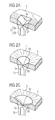
- prismatic deflecting elements 3a, 3b and 3c each with a Part of the light guide 2.
- a light source 5 consisting from a light emitting diode 5a and a light source reflector 5b, shown.
- the light generated in the light emitting diode 5a is either directly or via the light source reflector 5b via a light coupling surface 3d in the prismatic Lichtumlenkiata 3a, 3b, 3c coupled.
- the triangular prismatic light deflecting element 3a directs the light mainly in two opposite directions, as through the dashed illustrated exemplary light rays S shown.
- the conically tapered prismatic Lichtumlenkelement 3b allows a greater proportion of the injected Light also in the light deflecting 3b opposite sides of the light guide 2.
- the conical subdivided tapered prismatic Lichtumlenkelement 3c is a constructive and photometric combination the light deflecting elements 3a, 3b.
- the light deflecting element 3a is preferably for laterally longer light-guiding elements 2 used, the Lichtumlenkelement 3b at one in its geometric Surface area with similar aspect ratios
- Light guide elements and the Lichtumlenkelement 3c for light-guiding elements that make up a geometric combination represent the elements 3a, 3b.
- This in the light guide 2 existing light is directly light exit surface 2a (Fig. 1) radiated or reflected by the reflectors 4, until it is the light guide 2 at the light exit surface 2a leaves and then the area to be screened permeates and illuminates with it.
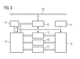
- Fig. 3 shows an example of the construction and the Functioning of a supply and control unit with Temperature control for the display.
- a processing module is shown 11, which via a transformer 13 and a Network 19 receives signals for controlling a display 18. To control the display in a defined way, the processing module uses 11 this data, z. B. temperature curves from a Memory 12 and a temperature driver 15. By means of display driver 16 and backlight driver 17 becomes the display 18 with relevant temperature changes in brightness and contrast readjusted.
Landscapes
- Physics & Mathematics (AREA)
- General Physics & Mathematics (AREA)
- Engineering & Computer Science (AREA)
- Theoretical Computer Science (AREA)
- Optics & Photonics (AREA)
- Planar Illumination Modules (AREA)
- Illuminated Signs And Luminous Advertising (AREA)
Applications Claiming Priority (2)
| Application Number | Priority Date | Filing Date | Title |
|---|---|---|---|
| DE2003145884 DE10345884A1 (de) | 2003-09-30 | 2003-09-30 | Anzeige mit Hinterleuchtungseinheit |
| DE10345884 | 2003-09-30 |
Publications (3)
| Publication Number | Publication Date |
|---|---|
| EP1521229A2 true EP1521229A2 (fr) | 2005-04-06 |
| EP1521229A3 EP1521229A3 (fr) | 2006-05-10 |
| EP1521229B1 EP1521229B1 (fr) | 2011-03-23 |
Family
ID=34306229
Family Applications (1)
| Application Number | Title | Priority Date | Filing Date |
|---|---|---|---|
| EP04103995A Expired - Lifetime EP1521229B1 (fr) | 2003-09-30 | 2004-08-20 | Dispositif d'affichage avec dispositif d'éclairage par l'arrière |
Country Status (2)
| Country | Link |
|---|---|
| EP (1) | EP1521229B1 (fr) |
| DE (2) | DE10345884A1 (fr) |
Cited By (1)
| Publication number | Priority date | Publication date | Assignee | Title |
|---|---|---|---|---|
| EP1808716A1 (fr) * | 2006-01-16 | 2007-07-18 | Samsung Electro-Mechanics Co., Ltd. | Panneau guide de lumière et dispositif d'affichage |
Families Citing this family (3)
| Publication number | Priority date | Publication date | Assignee | Title |
|---|---|---|---|---|
| DE202012101308U1 (de) * | 2012-04-12 | 2013-07-15 | Zumtobel Lighting Gmbh | Leuchte, insbesondere Hinweisleuchte |
| DE102017201125B4 (de) | 2017-01-25 | 2019-12-05 | Festo Ag & Co. Kg | Anzeigevorrichtung und damit ausgestattetes elektronisches Gerät |
| DE102022131598A1 (de) * | 2022-11-29 | 2024-05-29 | Marquardt Gmbh | Anzeigevorrichtung mit einem in einem keilförmigen Abschnitt gebildeten Übergang zur Ablenkung eines eine Anzeige verfälschenden Lichts |
Family Cites Families (5)
| Publication number | Priority date | Publication date | Assignee | Title |
|---|---|---|---|---|
| AU5232696A (en) * | 1988-06-23 | 1996-07-18 | Wilson, Ian Brownlie | Display apparatus |
| US6473554B1 (en) * | 1996-12-12 | 2002-10-29 | Teledyne Lighting And Display Products, Inc. | Lighting apparatus having low profile |
| JP4159059B2 (ja) * | 1998-06-05 | 2008-10-01 | シチズン電子株式会社 | 面状光源ユニット |
| JP4483020B2 (ja) * | 2000-04-21 | 2010-06-16 | パナソニック株式会社 | 面発光装置 |
| US6930737B2 (en) * | 2001-01-16 | 2005-08-16 | Visteon Global Technologies, Inc. | LED backlighting system |
-
2003
- 2003-09-30 DE DE2003145884 patent/DE10345884A1/de not_active Ceased
-
2004
- 2004-08-20 EP EP04103995A patent/EP1521229B1/fr not_active Expired - Lifetime
- 2004-08-20 DE DE200450012327 patent/DE502004012327D1/de not_active Expired - Lifetime
Cited By (3)
| Publication number | Priority date | Publication date | Assignee | Title |
|---|---|---|---|---|
| EP1808716A1 (fr) * | 2006-01-16 | 2007-07-18 | Samsung Electro-Mechanics Co., Ltd. | Panneau guide de lumière et dispositif d'affichage |
| US7573543B2 (en) | 2006-01-16 | 2009-08-11 | Samsung Electro-Mechanics Co., Ltd | Light guide panel and display device employing the same |
| EP2293124A1 (fr) * | 2006-01-16 | 2011-03-09 | Samsung LED Co., Ltd. | Panneau guide de lumière et dispositif d'affichage |
Also Published As
| Publication number | Publication date |
|---|---|
| EP1521229B1 (fr) | 2011-03-23 |
| DE10345884A1 (de) | 2005-05-12 |
| DE502004012327D1 (de) | 2011-05-05 |
| EP1521229A3 (fr) | 2006-05-10 |
Similar Documents
| Publication | Publication Date | Title |
|---|---|---|
| DE69228655T2 (de) | Flächige Beleuchtungsvorrichtung und mit solcher Vorrichtung versehenes Anzeigegerät | |
| DE69316010T2 (de) | Anzeige | |
| DE102005024083B4 (de) | Flächige, lichtemittierende Vorrichtung | |
| DE60224206T2 (de) | Hintergrundbeleuchtung für transmissive anzeigen | |
| DE10303969B4 (de) | Leuchtdiodenanordnung mit einem Leuchtdiodenträger und einer Mehrzahl von Leuchtdioden | |
| EP1438627A1 (fr) | Dispositif d'affichage | |
| EP3790756B1 (fr) | Élément de commande et/ou d'affichage pour véhicule automobile | |
| DE102004015903A1 (de) | Lichtemissionsdiodeneinrichtung | |
| DE202012013353U1 (de) | Optische Niederprofilbeleuchtungsbaugruppe zur Verwendung in einem Fahrzeug-Außenspiegel | |
| EP0400176A1 (fr) | Elément optique fixable sur une surface | |
| DE202005021754U1 (de) | Lichtemittierende Tafel | |
| DE102007043903A1 (de) | Leucht-Vorrichtung | |
| EP2534003B1 (fr) | Lampe de lecture pour véhicules automobiles | |
| WO2000039501A1 (fr) | Source lumineuse a couplage lateral oblique de lumiere | |
| EP1521229B1 (fr) | Dispositif d'affichage avec dispositif d'éclairage par l'arrière | |
| DE102006001490A1 (de) | Beleuchtungseinrichtung | |
| EP3853518B1 (fr) | Module d'éclairage, notamment destiné à être utilisé dans un dispositif d'éclairage pour véhicule automobile | |
| EP1505560B1 (fr) | Guide de lumière pour dispositifs d' affichage à segments multiples | |
| DE112019001649B4 (de) | Elektrische vorrichtung für ein fahrzeugtrittbrett | |
| DE102023116695A1 (de) | Beleuchtungsvorrichtung für ein Fahrzeug | |
| DE19860696A1 (de) | Lichtquellenelement mit seitlicher schräger Lichteinkopplung | |
| DE10143357B4 (de) | Starrer Lichtleiter | |
| EP3553371A1 (fr) | Élément lumineux pour lampes de véhicule automobile comprenant un guide de lumière en forme de plaque et véhicule automobile équipé d'un tel élément lumineux | |
| DE10303308A1 (de) | Kombiinstrument | |
| DE10108073B4 (de) | Leuchtvorrichtung |
Legal Events
| Date | Code | Title | Description |
|---|---|---|---|
| PUAI | Public reference made under article 153(3) epc to a published international application that has entered the european phase |
Free format text: ORIGINAL CODE: 0009012 |
|
| AK | Designated contracting states |
Kind code of ref document: A2 Designated state(s): AT BE BG CH CY CZ DE DK EE ES FI FR GB GR HU IE IT LI LU MC NL PL PT RO SE SI SK TR |
|
| AX | Request for extension of the european patent |
Extension state: AL HR LT LV MK |
|
| PUAL | Search report despatched |
Free format text: ORIGINAL CODE: 0009013 |
|
| AK | Designated contracting states |
Kind code of ref document: A3 Designated state(s): AT BE BG CH CY CZ DE DK EE ES FI FR GB GR HU IE IT LI LU MC NL PL PT RO SE SI SK TR |
|
| AX | Request for extension of the european patent |
Extension state: AL HR LT LV MK |
|
| 17P | Request for examination filed |
Effective date: 20061110 |
|
| AKX | Designation fees paid |
Designated state(s): DE FR IT |
|
| 17Q | First examination report despatched |
Effective date: 20070115 |
|
| RAP1 | Party data changed (applicant data changed or rights of an application transferred) |
Owner name: CONTINENTAL AUTOMOTIVE GMBH |
|
| GRAP | Despatch of communication of intention to grant a patent |
Free format text: ORIGINAL CODE: EPIDOSNIGR1 |
|
| GRAS | Grant fee paid |
Free format text: ORIGINAL CODE: EPIDOSNIGR3 |
|
| GRAA | (expected) grant |
Free format text: ORIGINAL CODE: 0009210 |
|
| AK | Designated contracting states |
Kind code of ref document: B1 Designated state(s): DE FR IT |
|
| REF | Corresponds to: |
Ref document number: 502004012327 Country of ref document: DE Date of ref document: 20110505 Kind code of ref document: P |
|
| REG | Reference to a national code |
Ref country code: DE Ref legal event code: R096 Ref document number: 502004012327 Country of ref document: DE Effective date: 20110505 |
|
| PLBE | No opposition filed within time limit |
Free format text: ORIGINAL CODE: 0009261 |
|
| STAA | Information on the status of an ep patent application or granted ep patent |
Free format text: STATUS: NO OPPOSITION FILED WITHIN TIME LIMIT |
|
| 26N | No opposition filed |
Effective date: 20111227 |
|
| REG | Reference to a national code |
Ref country code: DE Ref legal event code: R097 Ref document number: 502004012327 Country of ref document: DE Effective date: 20111227 |
|
| PGFP | Annual fee paid to national office [announced via postgrant information from national office to epo] |
Ref country code: IT Payment date: 20120822 Year of fee payment: 9 |
|
| PG25 | Lapsed in a contracting state [announced via postgrant information from national office to epo] |
Ref country code: IT Free format text: LAPSE BECAUSE OF NON-PAYMENT OF DUE FEES Effective date: 20130820 |
|
| REG | Reference to a national code |
Ref country code: FR Ref legal event code: PLFP Year of fee payment: 13 |
|
| REG | Reference to a national code |
Ref country code: FR Ref legal event code: PLFP Year of fee payment: 14 |
|
| REG | Reference to a national code |
Ref country code: DE Ref legal event code: R084 Ref document number: 502004012327 Country of ref document: DE |
|
| REG | Reference to a national code |
Ref country code: FR Ref legal event code: PLFP Year of fee payment: 15 |
|
| REG | Reference to a national code |
Ref country code: DE Ref legal event code: R081 Ref document number: 502004012327 Country of ref document: DE Owner name: CONTINENTAL AUTOMOTIVE TECHNOLOGIES GMBH, DE Free format text: FORMER OWNER: CONTINENTAL AUTOMOTIVE GMBH, 30165 HANNOVER, DE |
|
| PGFP | Annual fee paid to national office [announced via postgrant information from national office to epo] |
Ref country code: DE Payment date: 20220531 Year of fee payment: 19 |
|
| PGFP | Annual fee paid to national office [announced via postgrant information from national office to epo] |
Ref country code: FR Payment date: 20220823 Year of fee payment: 19 |
|
| P01 | Opt-out of the competence of the unified patent court (upc) registered |
Effective date: 20230522 |
|
| REG | Reference to a national code |
Ref country code: DE Ref legal event code: R119 Ref document number: 502004012327 Country of ref document: DE |
|
| PG25 | Lapsed in a contracting state [announced via postgrant information from national office to epo] |
Ref country code: FR Free format text: LAPSE BECAUSE OF NON-PAYMENT OF DUE FEES Effective date: 20230831 Ref country code: DE Free format text: LAPSE BECAUSE OF NON-PAYMENT OF DUE FEES Effective date: 20240301 |