EP1521647B1 - Presse a filage et procede correspondant - Google Patents
Presse a filage et procede correspondant Download PDFInfo
- Publication number
- EP1521647B1 EP1521647B1 EP03763679A EP03763679A EP1521647B1 EP 1521647 B1 EP1521647 B1 EP 1521647B1 EP 03763679 A EP03763679 A EP 03763679A EP 03763679 A EP03763679 A EP 03763679A EP 1521647 B1 EP1521647 B1 EP 1521647B1
- Authority
- EP
- European Patent Office
- Prior art keywords
- mould
- separating
- separating device
- strand
- cutting
- Prior art date
- Legal status (The legal status is an assumption and is not a legal conclusion. Google has not performed a legal analysis and makes no representation as to the accuracy of the status listed.)
- Expired - Lifetime
Links
Images
Classifications
-
- B—PERFORMING OPERATIONS; TRANSPORTING
- B23—MACHINE TOOLS; METAL-WORKING NOT OTHERWISE PROVIDED FOR
- B23D—PLANING; SLOTTING; SHEARING; BROACHING; SAWING; FILING; SCRAPING; LIKE OPERATIONS FOR WORKING METAL BY REMOVING MATERIAL, NOT OTHERWISE PROVIDED FOR
- B23D35/00—Tools for shearing machines or shearing devices; Holders or chucks for shearing tools
- B23D35/005—Adjusting the position of the cutting members
-
- B—PERFORMING OPERATIONS; TRANSPORTING
- B21—MECHANICAL METAL-WORKING WITHOUT ESSENTIALLY REMOVING MATERIAL; PUNCHING METAL
- B21C—MANUFACTURE OF METAL SHEETS, WIRE, RODS, TUBES, PROFILES OR LIKE SEMI-MANUFACTURED PRODUCTS OTHERWISE THAN BY ROLLING; AUXILIARY OPERATIONS USED IN CONNECTION WITH METAL-WORKING WITHOUT ESSENTIALLY REMOVING MATERIAL
- B21C35/00—Removing work or waste from extruding presses; Drawing-off extruded work; Cleaning dies, ducts, containers, or mandrels for metal extruding
- B21C35/04—Cutting-off or removing waste
Definitions
- the invention relates to an extruder, in particular for aluminum or Aluminum alloys, with a separator according to the preamble of Claim 1 and an extrusion process according to the preamble of Claim 7.
- Known extrusion presses have a separator, usually a Cylinder has, which at its lower end at least one cutting surface for having the separation process.
- the separator is required to one hand the To shear off press residue from the die or on the other hand from the recipient outstanding end of the bolt to provide a smooth cut.
- the separator in the rest position on the Muzzle of the die or the recipient arranged and can be used to carry out the Dividing section perpendicular to the extrusion direction at the mouth lowered over become.
- Different matrices are used. Also it can be for a big one Press order may be necessary to a die through a similar new die too replace, if at the originally used die wear and tear occur.
- German patent application DE 199 51 933 A1 proposed to store the shearing blade of the separating device so that always acting in the direction of the matrix adjusting force acts, the shear blade swings to the front of the die and holds in this position.
- a disadvantage of This device is that due to the constant force acting the Scraper along the matrix along and thus heavily worn.
- the aim of the invention is to provide an extruder with a separator for To provide and develop an extrusion process to ensure a clean Cross press seam to get.
- the clean Querpressnaht is achieved in particular by a slender knife, which two Having cutting surfaces that touch in a cutting tip and between enclose an acute angle smaller than 45 °. Preferably close the two cutting surfaces an angle of 20 °.
- the scissors well positioned and indeed as possible so that it does not drag along the hard steel material of the matrix.
- the cutting tools before the first separating cut positioned so that the distance of the cutting tip from the Front of the die is minimal. In this way, one with the front surface of the Matrix flush cut achieved.
- the cylinder of the Separating device are pivoted about a rotatable mounting. With that realized different angles of incidence of the knife to the die.
- Angle of attack as the angle between the intended separating interface - ie an area that is flush with the front of the die - and this one Dividing interface facing cutting surface of the separator, so this is Anstellwinkel very small, if the die has a position at which the new used die deviates from the normal position of a die with her Front further protrudes from the die holder. Dodges, however, the location of Die in such a way that the front side compared to the normal position set back is, then results in a larger angle of attack.
- the resting position over the muzzle of the die and arranged vertically aligned to the extrusion direction cylinder is used to adjust the Angle of attack, i. for positioning the cutting tip preferably on the Front of the die, pivoted with its lower end in the direction of the die.
- the cutting tip is pivoted so far until they Front of the die touches.
- This optimal position for the matrix used of the cylinder and thus optimal position of the separating cut surfaces and the Cutting tip should at each subsequent separating cut for the separation of the press residue be reached again by the matrix.
- the desired position stored. This can be on mechanical, hydraulic or electronic Ways are made.
- a tilted position of the cylinder can be transmitted to these components via the guide.
- the cylinder in lowered and swung-out position, i. the Cutting tip touches the front of the die, can simultaneously with this Movement or after reaching the position a stop mechanically, be moved and fixed electrically or hydraulically, which guarantees that at each subsequent swiveling movement to adjust the angle of attack exactly this same pivotal position of the cylinder is reached again.
- the cylinder during the return stroke after the separation cut of swivel off the front of the die, so that the return stroke no contact the Separating device with the die is present and thus no wear of the Cutting tools take place and no aluminum can start on the return stroke.
- the separator is again above the mouth the die and there is a new pressing process. As soon as a new bolt to an extrusion is pressed, the separator is again in the pivoted preset angle and moved down to the Remove press residue from the die. After swinging the Separator and the return stroke is then the next pressing step. This The process is repeated until a new die is needed for example, to press a new profile shape.
- the separating device for separating the press residue can at the counter spar or on Blockaufrichhalter be arranged. It is an application of the invention both For direct or indirect extrusion presses possible.
- this separator can also be used to separate the Bolt face of a protruding from the recipient of an extruder Metal bolt used to smooth before the pressing of the metal bolt To achieve bolt face and possibly adhering oxide particles or Remove lubricant residues. In this case it is possible to change the distance of the Set cutting tip from the front of the recipient in the desired manner.
- the extruder according to the invention with the above described separator for extruding aluminum or Aluminum alloys used.
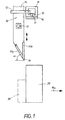
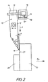
- Figs. 1 and 2 not all parts of the extruder are shown. to Description of the subject invention are these schematic diagrams gem.
- Fig. 1 and Fig. 2 which represent the die 20 and a part of the separating device 10, however sufficient.
- the separating device 10 is in the position shown in Fig. 1 in its rest position above the die 20.
- the separator 10 can be lowered from this rest position by a perpendicular to the extrusion direction (R ex ) aligned movement and raised by a return stroke. This movement is indicated by the double arrow shown.
- drive means are arranged on the separating device, which are not shown here.
- the separating device 10 is used to separate the pressing residue 30 from the die 20 or the separation of the pin end face of a protruding from the recipient of an extruder metal bolt.
- the pressing residue 30 is a part of the bolt, which can be separated from the die 20 at the end of an extrusion step and after the return of the recipient.
- Fig. 1 it is indicated where the pressing residue 30 is located after the pressing step.
- the extruded profile projects out of the die 20 in the extrusion direction R ex on the other side. For different profile shapes different tools - ie matrices 20 - used and even with signs of wear on the die used is an interruption of the extrusion process for a tool change is necessary.
- a newly inserted die 20 is inserted and held in the die receiver (not shown). If one then compares the position of the newly inserted die 20 with the position of the previously used die, then a deviation may result in practice.
- For the separation of the press residue 30 is a staggered in the extrusion direction layer or a staggered position in the opposite direction of disadvantage.
- the die 20 has a staggered in the extrusion direction position would cause a vertical movement of the separator 10 for the separation of a press residue, but it would remain a residual part of the press residue on the die 20. This leads to disturbances in the following pressing step, namely, when the recipient is moved back to the die 20, this residual part of the pressing residue 30 between the recipient and die 20 can be squeezed.
- the separator 10 is realigned. Such a reorientation the separator 10 is shown in FIG.
- the cylinder 14 of Separating device 10 is rotatably mounted.
- the bearing 12 thus allows a Pivoting the lower end of the cylinder 14 in the direction of die 20.
- To the Press rest 30 as completely as possible to separate from the die 20, is one with the Front 21 of the die 20 flush cut desired. For this reason the cylinder 14 of the separator 10 is swung so far until the Cutting tip 19, the front side 21 of the die 20 touched.
- the press residue 30 may tear off before the end of the separation cut.
- the cross-sectional area is not smooth and thus no smooth contact surface to the next bolt is guaranteed.
- the separating device 10 is equipped with two v-shaped cutting surfaces 11a, 11b which touch each other in the cutting tip 19.
- the cutting surfaces 11a, 11b include an acute angle ⁇ between them. This angle ⁇ is less than 45 °, preferably 20 °.
- an embodiment is shown in which a cutting surface 11 b is aligned almost parallel to the front side 21 of the die 20, ie almost parallel to the action of the cutting force F.
- This cutting surface 11 b is arranged as an extension at the lower end of the cylinder 14 and in the longitudinal direction of this Cylinder 14 attached.
- the second cutting surface 11a is provided at an angle ⁇ to the extrusion direction R ex or for the longitudinal alignment of the bolt and thus of the press residue 30.
- the cutting surfaces 11a, 11b are interchangeable fixed to the separator, which is not shown in the figures.
- the described arrangement of the cutting surfaces 11a, 11b is a preferred embodiment. However, other embodiments are conceivable. Essential to achieve a smooth separating cut is the arrangement of the cutting surfaces 11a, 11b to each other, namely the acute angle ⁇ .
- the cylinder 14 in the pivoted opposite direction and the lower end of the cylinder 14 of the front side 21 of the die 20 lifted. Is the separator 10 located again in the raised position can in the time where the next pressing step is made, the device back to the stored position be pivoted to prepare for the next separation cycle.
- the cylinder 14 of the separator is in a non-pivoted position, ie perpendicular to the extrusion direction R ex .
- the cylinder 14 is rigidly connected to the guide 18 via a holder 13.
- the stop 15, which engages in a recess of the guide 18, shows the position 17 on a possible arranged on the guide 18 setting scale 16. Now pivots the cylinder 14 to the bearing 12 in the angle ⁇ , so the cutting tip 19 moves in the direction Die 20, as shown in Fig. 2, so pivots the part of the cylinder 14 which is located above the storage 12, in the opposite direction.
- the guide 18 is moved by the rigid connection via the bracket 13.
- the engaging in the recess on the guide 18 stop 15 is not connected to the guide 18.
- This stop 15 does not change its position. With respect to the guide 18, however, its position on the arranged on the guide 18 adjustment scale changes 16.
- the now indicated position 17 'thus corresponds to the desired pivoted position of the cylinder 14 of the separator 10. Will after the return stroke of the separator 10, the cylinder 14th so far swung until the guide 18 of the stop 15 reaches the position 17 ', it is ensured in any case that the separator 10 with an angle ⁇ the separation of the press residue 30 will make. It is also possible that the stop 15 is not fixed in its position, moves when swinging the cylinder 14 together with the guide 18 in a new position. In this case, according to the found and desired position for the separating device 10 in the angle of attack ⁇ , the stop is determined independently of the guide 18.
- the stop 15 limits the longitudinal movement of the guide in this position and thus indicates the maximum value for the deflection about the bearing 12 and the maximum value for the angle ⁇ .
- the separating device 10 is then swung out to this maximum deflection.
- the position of the guide 18 can of course in other ways be measured and stored. It is also possible, for example, that of Pressure cylinder, which causes the pivoting movement of the cylinder 14, with the Guide 18 enters into operative connection. Another way of saving the desired position 17 'is to a differential proportional valve use that at the same time or after the pivoting of the separating device 10th is actuated and one of the corresponding position 17 'dependent Output signal to a programmable logic controller (PLC), by which this signal and thus the position 17 'is stored retrievably.
- PLC programmable logic controller
- the position 17 'of the cutting tip 19, the angle of attack ⁇ , the deflection of the cylinder 14 or the longitudinal displacement of the guide 18th electronically or optically to measure and these signals also to a programmable logic controller (PLC) from which the position 17 ' can be retrieved reproducibly.
- PLC programmable logic controller
- a metal bolt in particular made of aluminum or an aluminum alloy, for forming a metal profile strand, in particular an aluminum profile strand, are also pressed through the die 20 and the end of the respective metal bolt as press residue 30 by means of the separation device 10, perpendicular to the extrusion direction R ex exerts a cutting force F, separated from the die 20 before the next pressing step begins with another metal bolt.
- a die-dependent position 17 'of the cutting tools, in particular of the cutting surfaces 11a, 11b and the cutting tip 19, of the separating device 10 is set before the first pressing step or after a change of the die 20.
- a separator 10 can be at position an indirect extrusion press. Furthermore, can the Separator 10 also for the separation of the bolt end face of a Recipient of an extruder protruding metal bolt in front of his Use compression. It goes without saying that in the embodiment described, mechanically executed movement of the separator 10 with the help caused by hydraulic, electrical, electromagnetic or other forces can be, even a combination of such components is conceivable.
Landscapes
- Engineering & Computer Science (AREA)
- Mechanical Engineering (AREA)
- Extrusion Of Metal (AREA)
- Press Drives And Press Lines (AREA)
- Extrusion Moulding Of Plastics Or The Like (AREA)
Claims (13)
- Presse à filer, notamment pour aluminium ou alliages d'aluminium, comportant un dispositif de séparation (10),
le dispositif de séparation (10) possédant un cylindre pivotable (14) qui présente, à son extrémité inférieure, deux surfaces de coupe (11) disposées en forme de V l'une par rapport à l'autre, qui se touchent au niveau d'une pointe de coupe (19) et qui circonscrivent entre elles un angle aigu (γ) inférieur à 45° et
le cylindre (14) étant, en position de repos, disposé au dessus de l'embouchure d'une matrice (20) ou d'un récipient, tout en pouvant, pour réaliser une coupe de séparation, être descendu perpendiculairement au sens de la presse à filer (Rex) devant l'embouchure,
caractérisée en ce que
on peut régler d'avance une distance souhaitée pour une coupe de séparation entre la pointe de coupe (19) et la face frontale (21) de la matrice (20) ou du récipient,
cette distance réglée, qui équivaut à un certain angle d'approche (β) du cylindre (14), peut être enregistrée en mémoire,
pour réaliser une coupe de séparation, le cylindre (14) est pivotable de manière reproductible dans cet angle d'approche (β) réglé d'avance et est déplaçable suivant cet angle d'approche (β) réglé d'avance avec une force de coupe (F) vers le bas dans le sens vertical et
que les surfaces de coupe (11) du dispositif de séparation (10) peuvent pivoter avant la course de retour verticale. - Presse à filer selon la revendication 1, caractérisée en ce que l'angle (γ) s'élève de préférence à 20°.
- Presse à filer selon la revendication 1 ou 2, caractérisée en ce que, pour obtenir une coupe de séparation à fleur avec la surface frontale (21) de la matrice (20) lors de la séparation du résidu de presse (30) de la matrice (20), la distance entre la pointe de coupe (19) et la face frontale (21) de la matrice (20) est minimale.
- Presse à filer selon au moins une des revendications 1 à 3, caractérisée en ce que, pour régler la distance de la pointe de coupe (19), le cylindre (14) est pivotable au moyen d'un guide (18) relié rigidement (13) au cylindre (14) autour d'un palier rotatif (12) jusqu'à un angle d'approche souhaité (β), l'angle d'approche (β) étant l'angle entre la surface de séparation visée et celui de la surface de coupe tournée vers la surface de coupe de séparation (11) du dispositif de séparation (10).
- Presse à filer selon la revendication 4, caractérisée en ce que le guide (18) relié rigidement (13) au cylindre pivotable (14) est en liaison fonctionnelle directe ou indirecte avec des composants mécaniques ou hydrauliques ou électroniques, ces composants étant réglables en fonction de l'angle d'approche souhaité (β) et ce réglage étant consultable à répétition à un moment ultérieur lorsqu'on a besoin de l'angle d'approche souhaité (β) pour la coupe de séparation.
- Presse à filer selon la revendication 5, caractérisée en ce que, pour la course de retour du dispositif de séparation (10), après la coupe de séparation, la pointe de coupe (19) peut être relevée de la face frontale (21) de la matrice (20), tandis que le réglage des composants ne change pas.
- Procédé de filage par presse, dans lequel, en plusieurs étapes de presse se déroulant successivement, à chaque fois un goujon métallique, notamment un goujon en aluminium ou en alliage d'aluminium, est comprimé par une matrice (20) pour former une barre profilée métallique et l'extrémité du goujon métallique respectif est séparée de la matrice (20) en tant que résidu de presse (30) au moyen d'un dispositif de séparation (10) qui exerce une force de coupe (F) perpendiculairement au sens de la presse à filer (Rex) avant le début de l'étape de presse suivante avec un autre goujon métallique,
caractérisé en ce que,
avant la première étape de presse ou après un échange de matrice, une position (17') dépendante de la matrice des outils de coupe du dispositif de séparation (10) est réglée et ensuite enregistrée en mémoire,
qu'on avance à cette position (17') de manière reproductible avant chaque étape de séparation,
qu'on procède dans cette position (17') à la coupe de séparation verticale,
que cette position (17') est libérée avant la course de retour verticale du dispositif de séparation (10) par pivotement des outils de coupe du dispositif de séparation (10) de la matrice (20),
que la course de retour a lieu dans n'importe quelle position pivotée (17) des outils de coupe. - Procédé de filage par presse selon la revendication 7, caractérisé en ce que, pour régler la position (17') dépendante de la matrice, l'extrémité inférieure du dispositif de séparation (10) au niveau de laquelle se trouvent les surfaces de coupe (11) disposées en V les unes par rapport aux autres et se terminant en pointe de coupe (19) est descendue jusque devant l'embouchure de la matrice (20), que le dispositif de séparation (10) est pivoté autour d'un palier rotatif (12) en direction de la matrice (20) jusqu'à ce que la pointe de coupe (19) touche la face frontale (21) de la matrice (20) et que cette position pivotée (17') dépendante de la matrice de la pointe de coupe (19) du dispositif de séparation (10) est enregistrée en mémoire de manière à pouvoir la reconsulter.
- Procédé de filage par presse selon la revendication 8, caractérisé en ce que la position dépendante de la matrice (17') du dispositif de séparation (10) est communiquée par un guide (18) relié rigidement (13) au cylindre (14) du dispositif de séparation (10) à des composants réglables au niveau mécanique, hydraulique ou électronique et enregistrée en mémoire au moyen de ces composants.
- Procédé de filage par presse selon la revendication 9, caractérisé en ce qu'en même temps que le pivotement du dispositif de séparation (10), une butée (15) est déplacée directement ou indirectement par le guide (18) dans sa position et que la position dépendante de la matrice (17') est enregistrée en mémoire en fixant la butée (15) dans cette position.
- Procédé de filage par presse selon la revendication 10, caractérisé en ce qu'après le pivotement du dispositif de séparation (10), une butée (15) est amenée directement ou indirectement en contact avec le guide (18) et que la position dépendante de la matrice (17') est enregistrée en mémoire en fixant la butée (15) dans cette position.
- Procédé de filage par presse selon la revendication 10, caractérisé en ce qu'en même temps que ou après le pivotement du dispositif de séparation (10), une valve proportionnelle différentielle est actionnée directement ou indirectement par le guide (18), laquelle valve communique un signal de sortie correspondant à une position (17') dépendante de la matrice de la pointe de coupe (19) du dispositif de séparation (10) à une commande à mémoire programmable qui enregistre ce signal et donc la position (17') de manière à ce qu'on puisse la consulter.
- Procédé de filage par presse selon une des revendications 10 à 12, caractérisé en ce qu'avant de réaliser chaque coupe de séparation suivante, le dispositif de séparation (10) pivote vers la position (17') dépendante de la matrice enregistrée en mémoire.
Applications Claiming Priority (3)
| Application Number | Priority Date | Filing Date | Title |
|---|---|---|---|
| DE10231328 | 2002-07-11 | ||
| DE10231328A DE10231328B4 (de) | 2002-07-11 | 2002-07-11 | Strangpresse und Stangpressverfahren |
| PCT/EP2003/006978 WO2004007107A1 (fr) | 2002-07-11 | 2003-07-01 | Presse a filage et procede correspondant |
Publications (2)
| Publication Number | Publication Date |
|---|---|
| EP1521647A1 EP1521647A1 (fr) | 2005-04-13 |
| EP1521647B1 true EP1521647B1 (fr) | 2005-10-12 |
Family
ID=30009900
Family Applications (1)
| Application Number | Title | Priority Date | Filing Date |
|---|---|---|---|
| EP03763679A Expired - Lifetime EP1521647B1 (fr) | 2002-07-11 | 2003-07-01 | Presse a filage et procede correspondant |
Country Status (6)
| Country | Link |
|---|---|
| EP (1) | EP1521647B1 (fr) |
| JP (1) | JP2005537133A (fr) |
| AT (1) | ATE306333T1 (fr) |
| AU (1) | AU2003249915A1 (fr) |
| DE (1) | DE10231328B4 (fr) |
| WO (1) | WO2004007107A1 (fr) |
Families Citing this family (12)
| Publication number | Priority date | Publication date | Assignee | Title |
|---|---|---|---|---|
| JP5278690B2 (ja) * | 2009-06-03 | 2013-09-04 | 宇部興産機械株式会社 | 押出プレスのディスカード切断装置 |
| JP5278691B2 (ja) * | 2009-06-15 | 2013-09-04 | 宇部興産機械株式会社 | リアローディング型ショートストローク押出プレス |
| JP5448624B2 (ja) * | 2009-07-30 | 2014-03-19 | 昭和電工株式会社 | シャー刃およびアルミニウムの押出加工装置 |
| CN102000711B (zh) * | 2010-12-10 | 2012-08-08 | 西南铝业(集团)有限责任公司 | 挤压机及其挤压工具 |
| CN102198456A (zh) * | 2011-03-25 | 2011-09-28 | 瑞安市乐勤航空部件有限公司 | 镁合金型材挤压模具的清理装置及方法 |
| JP5831743B2 (ja) * | 2011-08-12 | 2015-12-09 | 宇部興産機械株式会社 | 押出プレスのシャー装置 |
| JP5780462B2 (ja) * | 2011-10-25 | 2015-09-16 | 宇部興産機械株式会社 | 押出プレスのシャー装置 |
| ES2686024T5 (es) | 2011-11-07 | 2021-12-15 | Sms Group Gmbh | Prensa de extrusión y extrusionadora para tubos y procedimiento para separar un residuo de prensado |
| ITMI20120053A1 (it) | 2012-01-19 | 2013-07-20 | Danieli Off Mecc | Pressa di estrusione diretta per prodotti metallici |
| CN114871290B (zh) * | 2022-05-23 | 2025-11-28 | 佛山市恒力泰机械有限公司 | 一种可摆动式压余剪 |
| DE102023104739A1 (de) * | 2022-11-14 | 2024-05-16 | Sms Group Gmbh | Pressrestschere sowie Verfahren zum Abscheren eines Pressrestes |
| CN117506438A (zh) * | 2023-11-09 | 2024-02-06 | 辽宁托田铝业有限公司 | 一种铝合金型材挤压模具成型设备 |
Family Cites Families (6)
| Publication number | Priority date | Publication date | Assignee | Title |
|---|---|---|---|---|
| US4793170A (en) * | 1987-06-19 | 1988-12-27 | Everett Daniels | Shear blade for aluminum extrusion process |
| JP2943970B2 (ja) * | 1994-05-31 | 1999-08-30 | 宇部興産株式会社 | 押出プレスのディスカード切断方法および装置 |
| DE19703576C2 (de) * | 1996-02-19 | 2001-05-17 | Alusuisse Tech & Man Ag | Vorrichtung zum Strangpressen eines Profils od. dgl. Körpers aus einem Barren |
| US5832767A (en) * | 1997-01-06 | 1998-11-10 | Alusuisse Technology & Management Ltd. | Process for extruding a section or the like from an ingot and a device for that purpose |
| JP2000263313A (ja) * | 1999-03-12 | 2000-09-26 | Murata Mach Ltd | 板材切断装置 |
| DE19951933A1 (de) * | 1999-10-28 | 2001-05-03 | Sms Eumuco Gmbh | Strangpresse bzw. Rohr- und Strangpresse |
-
2002
- 2002-07-11 DE DE10231328A patent/DE10231328B4/de not_active Expired - Fee Related
-
2003
- 2003-07-01 AU AU2003249915A patent/AU2003249915A1/en not_active Abandoned
- 2003-07-01 WO PCT/EP2003/006978 patent/WO2004007107A1/fr not_active Ceased
- 2003-07-01 JP JP2004520450A patent/JP2005537133A/ja active Pending
- 2003-07-01 EP EP03763679A patent/EP1521647B1/fr not_active Expired - Lifetime
- 2003-07-01 AT AT03763679T patent/ATE306333T1/de not_active IP Right Cessation
Also Published As
| Publication number | Publication date |
|---|---|
| ATE306333T1 (de) | 2005-10-15 |
| JP2005537133A (ja) | 2005-12-08 |
| EP1521647A1 (fr) | 2005-04-13 |
| WO2004007107A8 (fr) | 2005-03-17 |
| DE10231328B4 (de) | 2005-03-24 |
| WO2004007107A1 (fr) | 2004-01-22 |
| AU2003249915A1 (en) | 2004-02-02 |
| DE10231328A1 (de) | 2004-02-19 |
Similar Documents
| Publication | Publication Date | Title |
|---|---|---|
| DE10231328B4 (de) | Strangpresse und Stangpressverfahren | |
| DE2518243A1 (de) | Verfahren und vorrichtung zum schneiden von glas | |
| EP2776180B2 (fr) | Presse d'extrusion de tubes et de barres et procédé de séparation d'un résidu d'extrusion | |
| DE3641886A1 (de) | Verfahren und vorrichtung zum abtrennen aufeinanderfolgender rohrstuecke von einem rohr | |
| EP0040432B1 (fr) | Couteau râcleur pour cylindres, en particulier pour des cylindres de moulins de meunerie | |
| EP1848556B1 (fr) | Machine d'usinage comprenant un dispositif de coupe pour decouper une barre | |
| EP1103315B1 (fr) | Presse d'extrusion | |
| DE4212745A1 (de) | Beschneidwerkzeug zum Beschneiden von Ziehteilen am gesamten Umfang und zum gleichzeitigen Querschneiden des abgeschnittenen Abfallstreifens | |
| DE3239899C2 (de) | Vorrichtung an einer Stabstahlschere zum Abscheren von Abschnitten genauer Länge | |
| EP0787543A2 (fr) | Procédé d'extrusion de profilés ou analogues à partir de matériaux en barre et appareil à cet effet | |
| DE69300260T2 (de) | Verfahren und Vorrichtung zum Herstellen der Rechtwinkligkeit und zum Verschweissen metallischer Bänder. | |
| CH432192A (de) | Verfahren und Schneideinrichtung zum Zuschneiden von Aluminiumknüppeln auf eine vorgegebene Länge | |
| DE102017219289A1 (de) | Verfahren zum Trennen eines Gießstranges oder Zwischenbandes mittels einer Schere | |
| DE2332898A1 (de) | Flachmesserschere zum besaeumen von walzblechen | |
| EP0224115B1 (fr) | Appareil pour la séparation d'un disque de poussée du déchet dans l'extrusion de métaux à chemise | |
| DE3414233A1 (de) | Verfahren und vorrichtung zur erzielung genauer laengen an durch abscheren von stahl-stab- und knueppelmaterial sich ergebenden abschnitten zur verwendung als rohling fuer die massivumformung | |
| DE2718794A1 (de) | Verfahren und vorrichtung zum abscheren von warmwalzbaendern | |
| DE1303557B (de) | Verfahren und Vorrichtung zum Herstel len eines elektrischen Kontaktelements | |
| DE3319278C1 (de) | Schere | |
| DE3011134A1 (de) | Indirekt-metallstrangpresse mit einer mit dem aufnehmerhalter verbundenen vorrichtung zum abtrennen des pressrestes und zum auswechseln von matrizen | |
| DE19807159C1 (de) | Verfahren und Vorrichtung zum automatischen Ausscheiden der vorderen und hinteren Enden von in Umformpressen verarbeiteten Materialstangen | |
| EP4355510B1 (fr) | Machine de formage dotée d'un dispositif de cisaillement et procédé pour tailler une section de tige | |
| EP0570616A1 (fr) | Procédé de broyage, en particulier pour pneus usagés et dispositif pour sa mise en oeuvre | |
| DE3029234A1 (de) | Metallstrangpresse zum indirekten und direkten verpressen von metallen mit einer mit dem aufnehmerhalter verbundenen vorrichtung zum abtrennen des pressrestes und zum auswechseln von matrizen | |
| EP3606687A1 (fr) | Procédé et dispositif de coupe d'une pièce à usiner |
Legal Events
| Date | Code | Title | Description |
|---|---|---|---|
| PUAI | Public reference made under article 153(3) epc to a published international application that has entered the european phase |
Free format text: ORIGINAL CODE: 0009012 |
|
| 17P | Request for examination filed |
Effective date: 20050203 |
|
| AK | Designated contracting states |
Kind code of ref document: A1 Designated state(s): AT BE BG CH CY CZ DE DK EE ES FI FR GB GR HU IE IT LI LU MC NL PT RO SE SI SK TR |
|
| AX | Request for extension of the european patent |
Extension state: AL LT LV MK |
|
| GRAP | Despatch of communication of intention to grant a patent |
Free format text: ORIGINAL CODE: EPIDOSNIGR1 |
|
| RBV | Designated contracting states (corrected) |
Designated state(s): AT ES FR IT |
|
| REG | Reference to a national code |
Ref country code: DE Ref legal event code: 8566 |
|
| GRAS | Grant fee paid |
Free format text: ORIGINAL CODE: EPIDOSNIGR3 |
|
| GRAA | (expected) grant |
Free format text: ORIGINAL CODE: 0009210 |
|
| AK | Designated contracting states |
Kind code of ref document: B1 Designated state(s): AT ES FR IT |
|
| PG25 | Lapsed in a contracting state [announced via postgrant information from national office to epo] |
Ref country code: IT Free format text: LAPSE BECAUSE OF FAILURE TO SUBMIT A TRANSLATION OF THE DESCRIPTION OR TO PAY THE FEE WITHIN THE PRESCRIBED TIME-LIMIT;WARNING: LAPSES OF ITALIAN PATENTS WITH EFFECTIVE DATE BEFORE 2007 MAY HAVE OCCURRED AT ANY TIME BEFORE 2007. THE CORRECT EFFECTIVE DATE MAY BE DIFFERENT FROM THE ONE RECORDED. Effective date: 20051012 |
|
| PG25 | Lapsed in a contracting state [announced via postgrant information from national office to epo] |
Ref country code: ES Free format text: LAPSE BECAUSE OF FAILURE TO SUBMIT A TRANSLATION OF THE DESCRIPTION OR TO PAY THE FEE WITHIN THE PRESCRIBED TIME-LIMIT Effective date: 20060123 |
|
| PLBE | No opposition filed within time limit |
Free format text: ORIGINAL CODE: 0009261 |
|
| STAA | Information on the status of an ep patent application or granted ep patent |
Free format text: STATUS: NO OPPOSITION FILED WITHIN TIME LIMIT |
|
| 26N | No opposition filed |
Effective date: 20060713 |
|
| PG25 | Lapsed in a contracting state [announced via postgrant information from national office to epo] |
Ref country code: FR Free format text: LAPSE BECAUSE OF FAILURE TO SUBMIT A TRANSLATION OF THE DESCRIPTION OR TO PAY THE FEE WITHIN THE PRESCRIBED TIME-LIMIT Effective date: 20061020 |
|
| EN | Fr: translation not filed | ||
| PG25 | Lapsed in a contracting state [announced via postgrant information from national office to epo] |
Ref country code: AT Free format text: LAPSE BECAUSE OF NON-PAYMENT OF DUE FEES Effective date: 20060701 |
|
| PG25 | Lapsed in a contracting state [announced via postgrant information from national office to epo] |
Ref country code: FR Free format text: LAPSE BECAUSE OF FAILURE TO SUBMIT A TRANSLATION OF THE DESCRIPTION OR TO PAY THE FEE WITHIN THE PRESCRIBED TIME-LIMIT Effective date: 20051012 |