EP1521880B1 - Sensor für riemenriss - Google Patents
Sensor für riemenriss Download PDFInfo
- Publication number
- EP1521880B1 EP1521880B1 EP03763599A EP03763599A EP1521880B1 EP 1521880 B1 EP1521880 B1 EP 1521880B1 EP 03763599 A EP03763599 A EP 03763599A EP 03763599 A EP03763599 A EP 03763599A EP 1521880 B1 EP1521880 B1 EP 1521880B1
- Authority
- EP
- European Patent Office
- Prior art keywords
- sensor
- rupture
- detecting
- length change
- belt according
- Prior art date
- Legal status (The legal status is an assumption and is not a legal conclusion. Google has not performed a legal analysis and makes no representation as to the accuracy of the status listed.)
- Expired - Lifetime
Links
Images


Classifications
-
- G—PHYSICS
- G01—MEASURING; TESTING
- G01N—INVESTIGATING OR ANALYSING MATERIALS BY DETERMINING THEIR CHEMICAL OR PHYSICAL PROPERTIES
- G01N3/00—Investigating strength properties of solid materials by application of mechanical stress
- G01N3/08—Investigating strength properties of solid materials by application of mechanical stress by applying steady tensile or compressive forces
-
- D—TEXTILES; PAPER
- D06—TREATMENT OF TEXTILES OR THE LIKE; LAUNDERING; FLEXIBLE MATERIALS NOT OTHERWISE PROVIDED FOR
- D06F—LAUNDERING, DRYING, IRONING, PRESSING OR FOLDING TEXTILE ARTICLES
- D06F58/00—Domestic laundry dryers
- D06F58/02—Domestic laundry dryers having dryer drums rotating about a horizontal axis
- D06F58/04—Details
- D06F58/08—Driving arrangements
-
- F—MECHANICAL ENGINEERING; LIGHTING; HEATING; WEAPONS; BLASTING
- F16—ENGINEERING ELEMENTS AND UNITS; GENERAL MEASURES FOR PRODUCING AND MAINTAINING EFFECTIVE FUNCTIONING OF MACHINES OR INSTALLATIONS; THERMAL INSULATION IN GENERAL
- F16H—GEARING
- F16H57/00—General details of gearing
- F16H57/01—Monitoring wear or stress of gearing elements, e.g. for triggering maintenance
-
- F—MECHANICAL ENGINEERING; LIGHTING; HEATING; WEAPONS; BLASTING
- F16—ENGINEERING ELEMENTS AND UNITS; GENERAL MEASURES FOR PRODUCING AND MAINTAINING EFFECTIVE FUNCTIONING OF MACHINES OR INSTALLATIONS; THERMAL INSULATION IN GENERAL
- F16H—GEARING
- F16H7/00—Gearings for conveying rotary motion by endless flexible members
- F16H7/08—Means for varying tension of belts, ropes or chains
- F16H7/10—Means for varying tension of belts, ropes or chains by adjusting the axis of a pulley
- F16H7/12—Means for varying tension of belts, ropes or chains by adjusting the axis of a pulley of an idle pulley
- F16H7/1254—Means for varying tension of belts, ropes or chains by adjusting the axis of a pulley of an idle pulley without vibration damping means
- F16H7/1281—Means for varying tension of belts, ropes or chains by adjusting the axis of a pulley of an idle pulley without vibration damping means where the axis of the pulley moves along a substantially circular path
-
- F—MECHANICAL ENGINEERING; LIGHTING; HEATING; WEAPONS; BLASTING
- F16—ENGINEERING ELEMENTS AND UNITS; GENERAL MEASURES FOR PRODUCING AND MAINTAINING EFFECTIVE FUNCTIONING OF MACHINES OR INSTALLATIONS; THERMAL INSULATION IN GENERAL
- F16P—SAFETY DEVICES IN GENERAL; SAFETY DEVICES FOR PRESSES
- F16P7/00—Emergency devices preventing damage to a machine or apparatus
- F16P7/02—Emergency devices preventing damage to a machine or apparatus by causing the machine to stop on the occurrence of dangerous conditions therein
-
- F—MECHANICAL ENGINEERING; LIGHTING; HEATING; WEAPONS; BLASTING
- F16—ENGINEERING ELEMENTS AND UNITS; GENERAL MEASURES FOR PRODUCING AND MAINTAINING EFFECTIVE FUNCTIONING OF MACHINES OR INSTALLATIONS; THERMAL INSULATION IN GENERAL
- F16H—GEARING
- F16H7/00—Gearings for conveying rotary motion by endless flexible members
- F16H7/08—Means for varying tension of belts, ropes or chains
- F16H2007/0802—Actuators for final output members
- F16H2007/0808—Extension coil springs
-
- F—MECHANICAL ENGINEERING; LIGHTING; HEATING; WEAPONS; BLASTING
- F16—ENGINEERING ELEMENTS AND UNITS; GENERAL MEASURES FOR PRODUCING AND MAINTAINING EFFECTIVE FUNCTIONING OF MACHINES OR INSTALLATIONS; THERMAL INSULATION IN GENERAL
- F16H—GEARING
- F16H7/00—Gearings for conveying rotary motion by endless flexible members
- F16H7/08—Means for varying tension of belts, ropes or chains
- F16H2007/0861—Means for varying tension of belts, ropes or chains comprising means for sensing tensioner position
-
- F—MECHANICAL ENGINEERING; LIGHTING; HEATING; WEAPONS; BLASTING
- F16—ENGINEERING ELEMENTS AND UNITS; GENERAL MEASURES FOR PRODUCING AND MAINTAINING EFFECTIVE FUNCTIONING OF MACHINES OR INSTALLATIONS; THERMAL INSULATION IN GENERAL
- F16H—GEARING
- F16H57/00—General details of gearing
- F16H57/01—Monitoring wear or stress of gearing elements, e.g. for triggering maintenance
- F16H2057/014—Monitoring wear or stress of gearing elements, e.g. for triggering maintenance of friction elements in transmissions
-
- F—MECHANICAL ENGINEERING; LIGHTING; HEATING; WEAPONS; BLASTING
- F16—ENGINEERING ELEMENTS AND UNITS; GENERAL MEASURES FOR PRODUCING AND MAINTAINING EFFECTIVE FUNCTIONING OF MACHINES OR INSTALLATIONS; THERMAL INSULATION IN GENERAL
- F16H—GEARING
- F16H61/00—Control functions within control units of change-speed- or reversing-gearings for conveying rotary motion ; Control of exclusively fluid gearing, friction gearing, gearings with endless flexible members or other particular types of gearing
- F16H61/12—Detecting malfunction or potential malfunction, e.g. fail safe ; Circumventing or fixing failures
- F16H2061/1208—Detecting malfunction or potential malfunction, e.g. fail safe ; Circumventing or fixing failures with diagnostic check cycles; Monitoring of failures
-
- G—PHYSICS
- G01—MEASURING; TESTING
- G01N—INVESTIGATING OR ANALYSING MATERIALS BY DETERMINING THEIR CHEMICAL OR PHYSICAL PROPERTIES
- G01N2203/00—Investigating strength properties of solid materials by application of mechanical stress
- G01N2203/0014—Type of force applied
- G01N2203/0016—Tensile or compressive
- G01N2203/0017—Tensile
-
- G—PHYSICS
- G01—MEASURING; TESTING
- G01N—INVESTIGATING OR ANALYSING MATERIALS BY DETERMINING THEIR CHEMICAL OR PHYSICAL PROPERTIES
- G01N2203/00—Investigating strength properties of solid materials by application of mechanical stress
- G01N2203/003—Generation of the force
- G01N2203/005—Electromagnetic means
-
- G—PHYSICS
- G01—MEASURING; TESTING
- G01N—INVESTIGATING OR ANALYSING MATERIALS BY DETERMINING THEIR CHEMICAL OR PHYSICAL PROPERTIES
- G01N2203/00—Investigating strength properties of solid materials by application of mechanical stress
- G01N2203/0058—Kind of property studied
- G01N2203/006—Crack, flaws, fracture or rupture
- G01N2203/0067—Fracture or rupture
-
- G—PHYSICS
- G01—MEASURING; TESTING
- G01N—INVESTIGATING OR ANALYSING MATERIALS BY DETERMINING THEIR CHEMICAL OR PHYSICAL PROPERTIES
- G01N2203/00—Investigating strength properties of solid materials by application of mechanical stress
- G01N2203/02—Details not specific for a particular testing method
- G01N2203/026—Specifications of the specimen
- G01N2203/0262—Shape of the specimen
- G01N2203/0278—Thin specimens
- G01N2203/0282—Two dimensional, e.g. tapes, webs, sheets, strips, disks or membranes
Definitions
- the invention understood a sensor for detecting a crack and / or a change in length in a belt according to the preamble of patent claim 1.
- the drive of the drum by means of an electric motor via a drive belt.
- the drive belt is a wearing part, so that the tearing or breakage and / or an unacceptable elongation of the belt is to be monitored in order then, if necessary, to switch off the electric motor in good time or to initiate other measures.
- the known sensor for detecting a crack in a belt is provided with a movable transmission element operatively connected to the belt within a belt tensioning device and an electrical switch having a contact system.
- the transmission element acts in such a way on the electrical switch, that the contact system switches in case of impermissible change in length and / or crack of the belt.
- a belt tensioner for a tumble dryer which also has a sensor for detecting a crack in the belt.
- the belt tensioner consists of a belt tensioner and a spring-loaded carrier.
- the wearer operates a switch to turn off the tumble dryer.
- the switch is designed in the manner of a conventional electrical switch.
- the invention has for its object to provide a sensor for detecting a crack and / or a change in length in a belt with lower tolerance sensitivity.
- the contact system consists of a leaf spring having a contact surface having a switching contact and an associated fixed contact.
- the contact surface of the switch contact is arranged at a first end of the leaf spring, while the transmission element acts on the other second end of the leaf spring.
- a unilaterally free leg is approximately from the first end of the leaf spring in the direction of the second end and from the second end of the leaf spring in turn is another unilaterally free leg in the direction of the first end.
- the free ends of the two legs are each clamped to a support member of the switch with an offset to each other, so that the switching contact of the contact system cascade-like and bistable switches.
- the solution according to the invention avoids the disadvantages mentioned by using a bistable snap system with cascade as the contact system.
- a bistable snap system with cascade as the contact system.
- the actuated by the transmission element leaf spring-like switching contact snaps at the first crossing of the dead center.
- the area of the dead center lies on the side of the contact surface on the switching contact through the Offset the clamping points still sufficient contact force to safely carry the applied current.
- it is ensured even at extremely slow actuation of the switch that enough contact force is applied to the switching contact to the switching point to guide the current of the electric motor.
- the transmission element may be formed as a lever mounted on one side, wherein a roller for guiding the belt is arranged at the opposite end of the bearing of the lever.
- the transmission element is acted upon by means of an elastic element, in particular by means of a tension spring, in the direction of the switching contact.
- the contact system can be arranged in a housing, wherein the housing consists of a base and a latched by means of latching / snap connections on the base lid.
- the contact system is attached to the base.
- the support member may be injected for the switching contact in the base.
- the support member and the support member may protrude with their injected end in the manner of terminals of the housing, which eliminates the need for separate connections for the electrical leads to the sensor.
- the free ends of the two outgoing from the leaf spring leg can be clamped in approximately centrally with respect to the leaf spring, on opposite sides of the support member. As a result, a favorable actuation path is achieved until the contact system is switched over. Of course, however, another division of the lengths of the two legs on the leaf spring is possible. Conveniently, the clamping point is formed on the support member as a bearing notch in the manner of a cutting bearing.
- the transmission element in its movement act on an actuating element, which is movably mounted on the housing, in particular in a housing approach to the base.
- the actuator then in turn acts by means of a pin on the second end of the contact surface having leaf spring for switching the contact system.
- the contact system Since the contact system is bistable works, a re-closing of the circuit is possible only by operating a return element, for example in the manner of a reset button, whereby the risk of multiple switching in the border area is effectively prevented.
- the restoring element can be mounted so as to be movable on the housing, in particular on a housing projection on the base.
- the return element then also acts by means of a pin on the second end of the contact surface having leaf spring for re-switching the contact system.
- the respective pin protrudes through an opening in the housing projection on the base in the direction of the second end of the contact surface having leaf spring.
- the opening in the housing projection can be sealed by means of a seal surrounding the pin.
- the advantages achieved by the invention are in addition to the above-mentioned improvements, in particular, that the sensor is less sensitive to tolerances with respect to the length of the belt.
- the sensor has a precisely defined switching point. When switching the contact system performs a sudden electric opening between switching and fixed contact, so that itself when welded contacts switching is achieved. Finally, critical situations with regard to heating shortly before the switching point are reliably avoided even with respect to solutions with conventional switches.
- the sensor according to the invention works more reliable than previous sensors.
- the sensor is inexpensive to manufacture.
- an electric motor is used, which moves the drum via a drive belt.
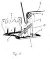
- a sensor 1 for detecting a crack and / or a change in length in a belt 2 is used, as in FIG Fig. 1 you can see.
- the sensor 1 is in a holder 3 in the household appliance, such as the tumble dryer, the washing machine o. The like., Attached.
- a movable transmission element 4 is arranged, which is in operative connection with the belt 2.
- the transmission element 4 is formed as a on the holder 3 on one side and rotatably mounted lever.
- a roller 6 is arranged, on which the belt 2 is guided along.
- an impermissible change in length and / or a crack of the belt 2 changes the position of the transmission element 4 and this acts in such an act on an electrical switch 7 with a in Fig. 3 visible contact system 8 that the contact system 8 switches.
- the corresponding switching signal of the electric switch 7 is then evaluated to determine the belt break or to change the length of the belt 2.
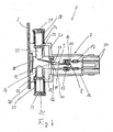
- the structure of the sensor 1 is closer in Fig. 3 and 4 to see.
- the contact system 8 consists of a leaf spring-like switching contact 9, wherein the leaf spring 9 is provided with a contact surface 13, and an associated fixed contact 10.
- the contact surface 13 of the switching contact 9 is connected to a first, in Fig. 4 right-hand end of the leaf spring 9 is arranged.
- the transmission element 4 acts on the other second, in Fig. 4 left end of the leaf spring 9 a.
- a unilaterally free leg 11 is approximately from the first end of the leaf spring 9 in the direction of the second end. From the second end of the leaf spring 9 in turn is another unilaterally free leg 12 in the direction of the first end.
- the free ends of the two legs 11, 12 are each clamped to a support member 26 of the switch 7 with an offset 27.
- the free end of the two outgoing from the leaf spring 9 legs 11, 12 approximately centrally with respect to the leaf spring 9, clamped on opposite sides on the support member 26, wherein the clamping points on the support member 26 formed as a bearing notch 29, 30 in the manner of a cutting bearing could be.
- the transmission element 4 by means of an elastic element, which is a tension spring 18, acted upon in the direction of the switching contact 9. Now tears the belt 2, the tension spring 18 pulls the transmission element 4 to the electrical switch 7, whereby the contact system 8, as described, switches.
- an elastic element which is a tension spring 18, acted upon in the direction of the switching contact 9.
- the contact system 8 is arranged in a housing 15. As in further Fig. 2 can be seen, is composed of plastic housing 15 from a base 16 and a lid 17 together, wherein the lid 17 is latched by means of latching / snap connections 28 on the base 16.
- the contact system 8 is attached to the base 16.
- the support member 26 is injected into the base 16 by the support member 26 in the manufacture of the base 16th molded by injection molding with the plastic used for the base 16, which is also out Fig. 4 closer.
- the contact surface 14 for the fixed contact 10 is arranged on a carrier element 19.
- the carrier element 19 is likewise injected in the base 16. Both the support member 19 and the support member 26 protrude respectively with their injected end in the manner of electrical connections 20 out of the housing 15, so that there the electrical leads can be attached.
- the transmission element 4 acts on an actuating element 21 during its movement, caused by the crack or the change in length of the belt 2.
- the configured in the manner of a plunger actuator 21 is mounted in the housing 15, in a housing projection 31 on the base 16, against a disposed on the housing extension 31 compression spring 25 movable.
- the actuating element 21 then acts in turn on the second end of the contact surface 13 having leaf spring 9 for switching the contact system 8 a.
- the actuating element 21 has a pin 22 which protrudes through an opening 23 in the housing projection 31 in the direction of the second end of the contact surface 13 having leaf spring 9.
- the switch 7 is provided with a return element 33.
- the restoring element 33 is the actuating element 21 opposite to the housing 15, on a housing extension 32 on the base 16, movably mounted against a arranged on the housing extension 32 compression spring 35.
- the return element 33 acts on the second end of the contact surface 13 having leaf spring 9 for re-switching the contact system 8 a.
- the sensor 1 thus works fail-safe even under the harsh operating conditions in a tumble dryer, a washing machine or other household appliance.
Landscapes
- Engineering & Computer Science (AREA)
- General Engineering & Computer Science (AREA)
- Mechanical Engineering (AREA)
- Textile Engineering (AREA)
- Physics & Mathematics (AREA)
- Health & Medical Sciences (AREA)
- Life Sciences & Earth Sciences (AREA)
- Chemical & Material Sciences (AREA)
- Analytical Chemistry (AREA)
- Biochemistry (AREA)
- General Health & Medical Sciences (AREA)
- General Physics & Mathematics (AREA)
- Immunology (AREA)
- Pathology (AREA)
- Mechanisms For Operating Contacts (AREA)
- Push-Button Switches (AREA)
- Control Of Washing Machine And Dryer (AREA)
Description
- Die Erfindung begriff einen Sensor zur Detektierung eines Risses und/oder einer Längenänderung in einem Riemen nach dem Oberbegriff des Patentanspruchs 1.
- In elektrischen Hausgeräten, wie in einem Wäschetrockner, einer Waschmaschine o. dgl., erfolgt der Antrieb der Trommel mittels eines Elektromotors über einen Antriebsriemen. Beim Antriebsriemen handelt es sich um ein Verschleißteil, so daß das Reißen bzw. der Bruch und/oder eine unzulässige Längung des Riemens zu überwachen ist, um dann gegebenenfalls den Elektromotor rechtzeitig abzuschalten oder sonstige Maßnahmen einzuleiten.
- Ein aus der
EP 0 110 318 A1 bekannter Sensor zur Detektierung eines Risses in einem Riemen ist mit einem bewegbaren Übertragungselement, das innerhalb einer Riemenspanneinrichtung in Wirkverbindung mit dem Riemen steht, und mit einem ein Kontaktsystem besitzenden elektrischen Schalter ausgestattet. Das Übertragungselement wirkt dabei derart auf den elektrischen Schalter ein, daß das Kontaktsystem bei unzulässiger Längenänderung und/oder Riß des Riemens umschaltet. - Bei diesem Sensor wird ein herkömmlicher Schalter als elektrischer Schalter verwendet. Es hat sich nun herausgestellt, daß die auftretenden Toleranzen bei der Riemenlänge sowie im Hinblick auf den Umschaltpunkt beim Schalter kritisch sind. Dies kann dazu führen, daß der Sensor nicht funktionssicher arbeitet. Im Fall der unzulässigen Längung des Riemens besteht zudem die Gefahr, daß der Schalter extrem langsam betätigt wird und - insbesondere bei Einsatz des konventionellen Schalters - bei Verharren kurz vor dem Schaltpunkt in Bereich einer Kontaktkraft von Null betrieben wird. Dadurch entsteht ein unsicherer Schaltzustand und die Gefahr der Kontaktverscliweißung. Durch eine leichte Hin- und Herbewegung der Spanneinrichtung ergibt sich außerdem die Gefahr des mehrfachen Einund Ausschaltens beim Betrieb in diesem Grenzbereich.
- Desweiteren ist aus der
US 3 890 720 A eine Riemenspanneinrichtung für einen Wäschetrockner bekannt, die ebenfalls einen Sensor zur Detektierung eines Risses im Riemen aufweist. Die Riemenspanneinrichtung besteht aus einer Riemenspannrolle und einem federgespannten Träger. Bei einem Riemenriß betätigt der Träger einen Schalter zum Abschalten des Wäschetrockners. Auch hier ist der Schalter in der Art eines konventionellen elektrischen Schalters ausgestaltet. - Der Erfindung liegt die Aufgabe zugrunde, einen Sensor zur Detektierung eines Risses und/oder einer Längenänderung in einem Riemen mit geringerer Toleranzempfindlichkeit anzugeben.
- Diese Aufgabe wird bei einem gattungsgemäßen Sensor durch die kennzeichnenden Merkmale des Anspruchs 1 gelöst.
- Beim erfindungsgemäßen Sensor besteht das Kontaktsystem aus einem eine Blattfeder mit einer Kontaktfläche aufweisenden Schaltkontakt und einem zugehörigen Festkontakt. Die Kontaktfläche des Schaltkontakts ist an einem ersten Ende der Blattfeder angeordnet, während das Übertragungselement auf das andere zweite Ende der Blattfeder einwirkt. Ein einseitig freier Schenkel geht in etwa vom ersten Ende der Blattfeder in Richtung zum zweiten Ende ab und vom zweiten Ende der Blattfeder geht wiederum ein weiterer einseitig freier Schenkel in Richtung zum ersten Ende ab. Die freien Enden der beiden Schenkel sind jeweils an einem Trägerteil des Schalters mit einem Versatz zueinander eingespannt, derart daß der Schaltkontakt des Kontaktsystems kaskadenartig sowie bistabil umschaltet.
- Die erfindungsgemäße Lösung vermeidet die genannten Nachteile, indem als Kontaktsystem ein bistabiles Schnappsystem mit Kaskade eingesetzt wird. Durch Versatz der beiden Einspannstellen am Trägerteil wird erreicht, daß der vom Übertragungselement betätigte blattfederartige Schaltkontakt beim ersten Überschreiten des Totpunktes umschnappt. Im Bereich des Totpunktes liegt auf der Seite der Kontaktfläche am Schaltkontakt durch den Versatz der Einspannstellen immer noch genügend Kontaktkraft an, um den anliegenden Strom sicher zu führen. Darüber hinaus wird auch bei extrem langsamer Betätigung des Schalters gewährleistet, daß bis zum Schaltpunkt genügend Kontaktkraft am Schaltkontakt anliegt, um den Strom des Elektromotors zu führen. Beim Umschnappen der dem Übertragungselement zugewandten Seite des Schaltkontakts wird auch die der Kontaktfläche zugewandte Seite des Schaltkontakts schlagartig über ihren Totpunkt geführt und der Stromkreis sicher unterbrochen. Aufgrund der Bistabilität wird weiterhin ein unzulässiges Hin- und Herschalten des Kontaktsystems im Bereich des Schaltpunktes vermieden.
- Weitere Ausgestaltungen der Erfindung sind Gegenstand der Unteransprüche.
- So kann das Übertragungselement als einseitig gelagerter Hebel ausgebildet sein, wobei eine Rolle zur Führung des Riemens an dem dem Lager gegenüberliegenden Ende des Hebels angeordnet ist. Das Übertragungselement ist mittels eines elastischen Elements, und zwar insbesondere mittels einer Zugfeder, in Richtung auf den Schaltkontakt beaufschlagt. Eine derartige Anordnung gewährleistet ein sofortiges und unverzögertes Umschalten des Kontaktsystems durch das Übertragungselement nach dem Reissen des Riemens.
- Um den Sensor vor Verschmutzungen und einen damit einhergehenden Ausfall zu bewahren, kann das Kontaktsystem in einem Gehäuse angeordnet sein, wobei das Gehäuse aus einem Sockel und einem mittels Rast-/Schnappverbindungen am Sockel verrasteten Deckel besteht. Das Kontaktsystem ist am Sockel befestigt. Der einfachen Herstellbarkeit halber bietet es sich an, die Kontaktfläche für den Festkontakt an einem Trägerelement anzuordnen und das Trägerelement im Sockel einzuspritzen. Ebenso kann das Trägerteil für den Schaltkontakt im Sockel eingespritzt sein. Das Trägerelement sowie das Trägerteil können mit deren eingespritztem Ende in der Art von Anschlüssen aus dem Gehäuse herausragen, womit sich separate Anschlüsse für die elektrischen Zuleitungen zum Sensor erübrigen.
- Die freien Enden der beiden von der Blattfeder abgehenden Schenkel können in etwa mittig bezüglich der Blattfeder, an einander gegenüberliegenden Seiten am Trägerteil eingespannt sein. Dadurch wird ein günstiger Betätigungsweg bis zum Umschalten des Kontaktsystems erreicht. Selbstverständlich ist jedoch auch eine andere Aufteilung der Längen der beiden Schenkel an der Blattfeder möglich. Zweckmäßigerweise ist die Einspannstelle am Trägerteil als Lagerkerbe in der Art eines Schneidenlagers ausgebildet.
- In weiterer Ausgestaltung kann das Übertragungselement bei dessen Bewegung auf ein Betätigungselement einwirken, das am Gehäuse, und zwar insbesondere in einem Gehäuseansatz am Sockel, bewegbar gelagert ist. Das Betätigungselement wirkt dann seinerseits mittels eines Zapfens, auf das zweite Ende der die Kontaktfläche aufweisenden Blattfeder zum Schalten des Kontaktsystems ein. Dadurch kann das Gehäuse mit Kontaktsystem und Betätigungselement als vormontiertes Bauteil zur Verfügung gestellt werden, um dann eine einfache Endmontage in der gesamten Baugruppe für den Sensor zu gestatten.
- Da das Kontaktsystem bistabil arbeitet ist, ist ein erneutes Schließen des Stromkreises nur durch Betätigung eines Rückstellelementes, beispielsweise in der Art eines Rückstellknopfes möglich, womit die Gefahr des Mehrfachschaltens im Grenzbereich wirksam verhindert ist. Um wiederum ein vormontierbares Bauteil zur Verfügung zu stellen, kann das Rückstellelement gegenüberliegend am Gehäuse, und zwar insbesondere an einem Gehäuseansatz am Sockel, bewegbar gelagert sein. Das Rückstellelement wirkt dann ebenfalls mittels eines Zapfens auf das zweite Ende der die Kontaktfläche aufweisenden Blattfeder zum erneuten Umschalten des Kontaktsystems ein.
- Es bietet sich an, daß der jeweilige Zapfen durch eine Öffnung im Gehäuseansatz am Sockel in Richtung auf das zweite Ende der die Kontaktfläche aufweisenden Blattfeder hindurchragt. Um das Eindringen von Staub in das Gehäuse an der Öffnung zu verhindern, kann die Öffnung im Gehäuseansatz mittels einer den Zapfen umgebenden Dichtung abgedichtet sein. Damit das Betätigungs- sowie das Rückstellelement gegen eine elastische Kraft bewegbar sind, kann schließlich am jeweiligen Gehäuseansatz eine Druckfeder sowohl für das Betätigungselement als auch für das Rückstellelement angeordnet sein.
- Die mit der Erfindung erzielten Vorteile bestehen neben den bereits genannten Verbesserungen insbesondere darin, daß der Sensor gegenüber Toleranzen im Hinblick auf die Länge des Riemens wenig empfindlich ist. Trotz einfacher Ausgestaltung besitzt der Sensor einen präzise definierten Umschaltpunkt. Beim Umschalten führt das Kontaktsystem eine schlagartige elektrische Öffnung zwischen Schalt- und Festkontakt aus, so daß selbst bei verschweißten Kontakten ein Umschalten erreicht wird. Schließlich werden auch gegenüber Lösungen mit herkömmlichen Schaltern kritische Situationen hinsichtlich Erwärmung kurz vor dem Schaltpunkt sicher vermieden. Damit arbeitet der erfindungsgemäße Sensor funktionssicherer als bisherige Sensoren. Zudem ist der Sensor kostengünstig herzustellen.
- Ein Ausführungsbeispiel der Erfindung ist in den Zeichnungen dargestellt und wird im folgenden näher beschrieben. Es zeigen
- Fig. 1
- eine Baugruppe mit einem Sensor zur Detektierung eines Risses in einem Riemen für ein Hausgerät in perspektivischer Ansicht,
- Fig. 2
- den Sensor aus
Fig. 1 in perspektivischer Ansicht, - Fig. 3
- den Sensor wie in
Fig. 2 , jedoch mit abgenommenem Deckel und somit geöffnetem Gehäuse und - Fig. 4
- den Sensor aus
Fig. 2 im Längsschnitt. - Zum Antrieb einer Trommel in einem Wäschetrockner, einer Waschmaschine oder einem sonstigen Hausgerät wird ein Elektromotor verwendet, der die Trommel über einen Antriebsriemen bewegt. Zur Feststellung eines Risses und/oder einer unzulässigen Längenänderung des Antriebsriemens findet ein Sensor 1 zur Detektierung eines Risses und/oder einer Längenänderung in einem Riemen 2 Verwendung, wie in
Fig. 1 zu sehen ist. - Der Sensor 1 ist in einer Halterung 3 im Hausgerät, wie dem Wäschetrockner, der Waschmaschine o. dgl., befestigt. An der Halterung 3 ist ein bewegbares Übertragungselement 4 angeordnet, das in Wirkverbindung mit dem Riemen 2 steht. Hierzu ist das Übertragungselement 4 als ein an der Halterung 3 einseitig und drehbar gelagerter Hebel ausgebildet. An dem dem Lager 5 gegenüberliegenden Ende des Hebels vom Übertragungselement 4 ist eine Rolle 6 angeordnet, an der der Riemen 2 entlanggeführt ist. Bei einer unzulässigen Längenänderung und/oder einem Riß des Riemens 2 verändert sich die Lage des Übertragungselementes 4 und dieses wirkt dabei derart auf einen elektrischen Schalter 7 mit einem in
Fig. 3 sichtbaren Kontaktsystem 8 ein, daß das Kontaktsystem 8 umschaltet. Das entsprechende Schaltsignal des elektrischen Schalters 7 wird dann zur Feststellung des Riemenrisses bzw. zur Längenänderung des Riemens 2 ausgewertet. - Der Aufbau des Sensors 1 ist näher in
Fig. 3 und4 zu sehen. Das Kontaktsystem 8 besteht aus einem blattfederartigen Schaltkontakt 9, wobei die Blattfeder 9 mit einer Kontaktfläche 13 versehen ist, und einem zugehörigen Festkontakt 10. Die Kontaktfläche 13 des Schaltkontakts 9 ist an einem ersten, inFig. 4 rechts liegende Ende der Blattfeder 9 angeordnet. Das Übertragungselement 4 wirkt auf das andere zweite, inFig. 4 links liegende Ende der Blattfeder 9 ein. Ein einseitig freier Schenkel 11 geht in etwa vom ersten Ende der Blattfeder 9 in Richtung zum zweiten Ende ab. Vom zweiten Ende der Blattfeder 9 geht wiederum ein weiterer einseitig freier Schenkel 12 in Richtung zum ersten Ende ab. Die freien Enden der beiden Schenkel 11, 12 sind jeweils an einem Trägerteil 26 des Schalters 7 mit einem Versatz 27 eingespannt. Bevorzugterweise ist das freie Ende der beiden von der Blattfeder 9 abgehenden Schenkel 11, 12 in etwa mittig bezüglich der Blattfeder 9, an einander gegenüberliegenden Seiten am Trägerteil 26 eingespannt, wobei die Einspannstellen am Trägerteil 26 als Lagerkerbe 29, 30 in der Art eines Schneidenlagers ausgebildet sein können. Durch Einwirkung des Übertragungselementes 4 schaltet dann der Schaltkontakt 9 des Kontaktsystems 8 kaskadenartig sowie bistabil um. - Wie anhand der
Fig. 1 zu erkennen ist, ist das Übertragungselement 4 mittels eines elastischen Elements, bei dem es sich um eine Zugfeder 18 handelt, in Richtung auf den Schaltkontakt 9 beaufschlagt. Reißt nun der Riemen 2, so zieht die Zugfeder 18 das Übertragungselement 4 zum elektrischen Schalter 7, womit dessen Kontaktsystem 8, wie beschrieben, umschaltet. - Das Kontaktsystem 8 ist in einem Gehäuse 15 angeordnet. Wie weiter in
Fig. 2 zu sehen ist, setzt sich das aus Kunststoff bestehende Gehäuse 15 aus einem Sockel 16 und einem Deckel 17 zusammen, wobei der Deckel 17 mittels Rast-/Schnappverbindungen 28 am Sockel 16 verrastet ist. Das Kontaktsystem 8 ist am Sockel 16 befestigt. Hierfür ist das Trägerteil 26 in den Sockel 16 eingespritzt, indem das Trägerteil 26 bei der Herstellung des Sockels 16 durch Spritzgießen mit dem für den Sockel 16 verwendeten Kunststoff umspritzt wird, was auch ausFig. 4 näher hervorgeht. Die Kontaktfläche 14 für den Festkontakt 10 ist an einem Trägerelement 19 angeordnet. Das Trägerelement 19 ist ebenfalls im Sockel 16 eingespritzt. Sowohl das Trägerelement 19 als auch das Trägerteil 26 ragen jeweils mit deren eingespritztem Ende in der Art von elektrischen Anschlüssen 20 aus dem Gehäuse 15 heraus, so daß dort die elektrischen Zuleitungen befestigt werden können. - Das Übertragungselement 4 wirkt bei dessen Bewegung, hervorgerufen durch den Riß bzw. der Längenänderung des Riemens 2, auf ein Betätigungselement 21 ein. Das in der Art eines Stößels ausgestaltete Betätigungselement 21 ist im Gehäuse 15, und zwar in einem Gehäuseansatz 31 am Sockel 16, gegen eine am Gehäuseansatz 31 angeordnete Druckfeder 25 bewegbar gelagert. Dabei wirkt das Betätigungselement 21 dann seinerseits auf das zweite Ende der die Kontaktfläche 13 aufweisenden Blattfeder 9 zum Schalten des Kontaktsystem 8 ein. Hierzu besitzt das Betätigungselement 21 einen Zapfen 22, der durch eine Öffnung 23 im Gehäuseansatz 31 in Richtung auf das zweite Ende der die Kontaktfläche 13 aufweisenden Blattfeder 9 hindurchragt.
- Wegen der bistabilen Ausführung des Kontaktsystems 8 ist der Schalter 7 mit einem Rückstellelement 33 versehen. Das Rückstellelement 33 ist dem Betätigungselement 21 gegenüberliegend am Gehäuse 15, und zwar an einem Gehäuseansatz 32 am Sockel 16, gegen eine am Gehäuseansatz 32 angeordnete Druckfeder 35 bewegbar gelagert. Wiederum mittels eines Zapfens 34, der ebenfalls durch eine Öffnung 23' im Gehäuseansatz 32 in Richtung auf das zweite Ende der Blattfeder 9 hindurchragt, wirkt das Rückstellelement 33 auf das zweite Ende der die Kontaktfläche 13 aufweisenden Blattfeder 9 zum erneuten Umschalten des Kontaktsystems 8 ein. Mittels des Rückstellelements 33 kann somit nach einer Reparatur des Riemens 2 das Kontaktsystem 8 des Schalters 7 manuell zurückgeschaltet werden, womit der Sensor 1 für den nachfolgenden Betrieb des Wäschetrockners o. dgl. wiederum aktiviert ist.
- Um das Eindringen von Schmutz, Staub o. dgl. in das Gehäuse 15 zu verhindern, sind die Öffnungen 23, 23' im Gehäuseansatz 31, 32 mittels einer den jeweiligen Zapfen 22, 34 umgebenden Dichtung 24, 24' abgedichtet. Eine Abdichtung an den Anschlüssen 20 wird dadurch erzielt, indem diese in den Sockel 16 eingespritzt sind. Der Sensor 1 arbeitet damit ausfallsicher auch unter den rauhen Einsatzbedingungen in einem Wäschetrockner, einer Waschmaschine oder einem sonstigen Hausgerät.
- Die Erfindung ist nicht auf das beschriebene und dargestellte Ausführungsbeispiel beschränkt. Sie umfaßt vielmehr auch alle fachmännischen Weiterbildungen im Rahmen der durch die Patentansprüche definierten Erfindung. So kann ein derartiger Sensor 1 nicht nur in Haushaltsgeräten, wie Waschmaschinen, Wäschetrocknern o. dgl., sondern auch an sonstigen Riemen-Antrieben, beispielsweise von Werkzeugmaschinen, von Fahrzeugen o. dgl., Verwendung finden.
-
- 1:
- Sensor (für Riemenriß)
- 2:
- Riemen
- 3:
- Halterung
- 4:
- Übertragungselement
- 5:
- Lager (für Übertragungselement)
- 6:
- Rolle
- 7:
- elektrischer Schalter
- 8:
- Kontaktsystem
- 9:
- Schaltkontakt / Blattfeder
- 10:
- Festkontakt
- 11,12:
- freier Schenkel (an Blattfeder)
- 13:
- Kontaktfläche (von Schaltkontakt)
- 14:
- Kontaktfläche (von Festkontakt)
- 15:
- Gehäuse
- 16:
- Sockel
- 17:
- Deckel
- 18:
- Zugfeder
- 19:
- Trägerelement (von Festkontakt)
- 20:
- Anschluß
- 21:
- Betätigungselement
- 22:
- Zapfen (am Betätigungselement)
- 23,23':
- Öffnung (im Gehäuse)
- 24,24':
- Dichtung
- 25:
- Druckfeder (am Betätigungselement)
- 26:
- Trägerteil
- 27:
- Versatz
- 28:
- Rast-/Schnappverbindung
- 29,30:
- Lagerkerbe (am Trägerteil)
- 31,32:
- Gehäuseansatz
- 33:
- Rückstellelement
- 34:
- Zapfen (am Rückstellelement)
- 35:
- Druckfeder (am Rückstellelement)
Claims (21)
- Sensor zur Detektierung eines Risses und/oder einer Längenänderung in einem Riemen, insbesondere in einem Antriebsriemen für einen Elektromotor, wie für einen Wäschetrockner, eine Waschmaschine o. dgl., mit einem bewegbaren Übertragungselement (4), das in Wirkverbindung mit dem Riemen (2) steht, und mit einem ein Kontaktsystem (8) besitzenden elektrischen Schalter (7), wobei das Übertragungselement (4) derart auf den elektrischen Schalters (7) einwirkt, daß das Kontaktsystem (8) bei unzulässiger Längenänderung und/oder Riß des Riemens (2) umschaltet, dadurch gekennzeichnet, daß das Kontaktsystem (8) aus einem eine Blattfeder mit einer Kontaktfläche (13) aufweisenden Schaltkontakt (9) und einem zugehörigen Festkontakt (10) besteht, daß die Kontaktfläche (13) des Schaltkontakts (9) an einem ersten Ende der Blattfeder (9) angeordnet ist, daß das Übertragungselement (4) auf das andere zweite Ende der Blattfeder (9) einwirkt, daß ein einseitig freier Schenkel (11) in etwa vom ersten Ende der Blattfeder (9) in Richtung zum zweiten Ende abgeht, daß vom zweiten Ende der Blattfeder (9) ein weiterer einseitig freier Schenkel (12) in Richtung zum ersten Ende abgeht, und daß jeweils die freien Enden der beiden Schenkel (11, 12) an einem Trägerteil (26) des Schalters (7) mit einem Versatz (27) zueinander eingespannt sind, derart daß der Schaltkontakt (9) des Kontaktsystems (8) kaskadenartig sowie bistabil umschaltet.
- Sensor zur Detektierung eines Risses und/oder einer Längenänderung in einem Riemen nach Anspruch 1, dadurch gekennzeichnet, daß das Übertragungselement (4) als einseitig gelagerter Hebel ausgebildet ist, daß eine Rolle (6) an dem dem Lager (5) gegenüberliegenden Ende des Hebels angeordnet ist, wobei der Riemen (2) an der Rolle (6) entlanggeführt ist, und daß das Übertragungselement (4) mittels eines elastischen Elements, insbesondere mittels einer Zugfeder (18), in Richtung auf den Schaltkontakt (9) beaufschlagt ist.
- Sensor zur Detektierung eines Risses und/oder einer Längenänderung in einem Riemen nach Anspruch 1 oder 2, dadurch gekennzeichnet, daß das Kontaktsystem (8) in einem Gehäuse (15) angeordnet ist, wobei das Gehäuse (15) aus einem Sockel (16) und einem Deckel (17) besteht.
- Sensor zur Detektierung eines Risses und/oder einer Längenänderung in einem Riemen nach Anspruch 3, dadurch gekennzeichnet, daß der Deckel (17) mittels Rast-/ Schnappverbindungen (28) am Sockel (16) verrastet ist.
- Sensor zur Detektierung eines Risses und/oder einer Längenänderung in einem Riemen nach Anspruch 3 oder 4, dadurch gekennzeichnet, daß das Kontaktsystem (8) am Sockel (16) befestigt ist.
- Sensor zur Detektierung eines Risses und/oder einer Längenänderung in einem Riemen nach einem der Ansprüche 1 bis 5, dadurch gekennzeichnet, daß die Kontaktfläche (14) für den Festkontakt (10) an einem Trägerelement (19) angeordnet ist.
- Sensor zur Detektierung eines Risses und/oder einer Längenänderung in einem Riemen nach Anspruch 6, dadurch gekennzeichnet, daß das Trägerelement (19) im Sockel (16) eingespritzt ist, daß das Trägerteil (26) im Sockel (16) eingespritzt ist, und daß das Trägerelement (19) sowie das Trägerteil (26) mit deren eingespritzten Enden in der Art von elektrischen Anschlüssen (20) aus dem Gehäuse (15) herausragen.
- Sensor zur Detektierung eines Risses und/oder einer Längenänderung in einem Riemen nach einem der Ansprüche 1 bis 7, dadurch gekennzeichnet, daß die freien Enden der beiden von der Blattfeder (9) abgehenden Schenkel (11, 12) in etwa mittig bezüglich der Blattfeder (9), an einander gegenüberliegenden Seiten am Trägerteil (26) eingespannt sind.
- Sensor zur Detektierung eines Risses und/oder einer Längenänderung in einem Riemen nach Anspruch 8, dadurch gekennzeichnet, daß die Einspannstelle am Trägerteil (26) als Lagerkerbe (29, 30) in der Art eines Schneidenlagers ausgebildet ist.
- Sensor zur Detektierung eines Risses und/oder einer Längenänderung in einem Riemen nach einem der Ansprüche 3 bis 9, dadurch gekennzeichnet, daß das Übertragungselement (4) bei dessen Bewegung auf ein Betätigungselement (21) einwirkt.
- Sensor zur Detektierung eines Risses und/oder einer Längenänderung in einem Riemen nach Anspruch 10, dadurch gekennzeichnet, daß das Betätigungselement (21) im Gehäuse (15) bewegbar gelagert ist.
- Sensor zur Detektierung eines Risses und/oder einer Längenänderung in einem Riemen nach Anspruch 11, dadurch gekennzeichnet, daß das Betätigungselement (21) an einem Gehäuseansatz (31) am Sockel (16) bewegbar gelagert ist.
- Sensor zur Detektierung eines Risses und/oder einer Längenänderung in einem Riemen nach Anspruch 12, dadurch gekennzeichnet, daß das Betätigungselement (21) seinerseits mittels eines Zapfens (22) auf das zweite Ende der die Kontaktfläche (13) aufweisenden Blattfeder (9) zum Schalten des Kontaktsystems (8) einwirkt.
- Sensor zur Detektierung eines Risses und/oder einer Längenänderung in einem Riemen nach Anspruch 13, dadurch gekennzeichnet, daß dem Betätigungselement (21) gegenüberliegend am Gehäuse (15) ein Rückstellelement (33) bewegbar gelagert ist.
- Sensor zur Detektierung eines Risses und/oder einer Längenänderung in einem Riemen nach Anspruch 14, dadurch gekennzeichnet, daß das Rückstellelement (33) an einem Gehäuseansatz (32) am Sockel (16) bewegbar gelagert ist.
- Sensor zur Detektierung eines Risses und/oder einer Längenänderung in einem Riemen nach Anspruch 15, dadurch gekennzeichnet, daß das Rückstellelement (33) mittels eines Zapfens (34) auf das zweite Ende der die Kontaktfläche (13) aufweisenden Blattfeder (9) zum erneuten Umschalten des Kontaktsystems (8) einwirkt.
- Sensor zur Detektierung eines Risses und/oder einer Längenänderung in einem Riemen nach Anspruch 16, dadurch gekennzeichnet, daß der Zapfen (22) am Betätigungselement (21) durch eine Öffnung (23) im Gehäuseansatz (31) am Sockel (16) in Richtung auf das zweite Ende der die Kontaktfläche (13) aufweisenden Blattfeder (9) hindurchragt.
- Sensor zur Detektierung eines Risses und/oder einer Längenänderung in einem Riemen nach Anspruch 17, dadurch gekennzeichnet, daß die Öffnung (23) im Gehäuseansatz (31) mittels einer den Zapfen (22) am Betätigungselement (21) umgebenden Dichtung (24) abgedichtet ist.
- Sensor zur Detektierung eines Risses und/oder einer Längenänderung in einem Riemen nach einem der Ansprüche 17 oder 18, dadurch gekennzeichnet, daß der Zapfen (34) am Rückstellelement (33) durch eine Öffnung (23') im Gehäuseansatz (32) am Sockel (16) in Richtung auf das zweite Ende der die Kontaktfläche (13) aufweisenden Blattfeder (9) hindurchragt.
- Sensor zur Detektierung eines Risses und/oder einer Längenänderung in einem Riemen nach Anspruch 19, dadurch gekennzeichnet, daß die Öffnung (23') im Gehäuseansatz (32) mittels einer den Zapfen (34) am Rückstellelement (33) umgebenden Dichtung (24') abgedichtet ist.
- Sensor zur Detektierung eines Risses und/oder einer Längenänderung in einem Riemen nach einem der Ansprüche 17 bis 20, dadurch gekennzeichnet, daß das Betätigungselement (21) sowie das Rückstellelement (33) jeweils gegen eine am Gehäuseansatz (31, 32) angeordnete Druckfeder (25, 35) bewegbar sind.
Applications Claiming Priority (3)
| Application Number | Priority Date | Filing Date | Title |
|---|---|---|---|
| DE10231078 | 2002-07-10 | ||
| DE10231078 | 2002-07-10 | ||
| PCT/DE2003/002298 WO2004007828A1 (de) | 2002-07-10 | 2003-07-09 | Sensor für riemenriss |
Publications (2)
| Publication Number | Publication Date |
|---|---|
| EP1521880A1 EP1521880A1 (de) | 2005-04-13 |
| EP1521880B1 true EP1521880B1 (de) | 2011-11-02 |
Family
ID=29761827
Family Applications (1)
| Application Number | Title | Priority Date | Filing Date |
|---|---|---|---|
| EP03763599A Expired - Lifetime EP1521880B1 (de) | 2002-07-10 | 2003-07-09 | Sensor für riemenriss |
Country Status (5)
| Country | Link |
|---|---|
| US (1) | US6967297B2 (de) |
| EP (1) | EP1521880B1 (de) |
| AT (1) | ATE531844T1 (de) |
| DE (1) | DE10330936A1 (de) |
| WO (1) | WO2004007828A1 (de) |
Families Citing this family (10)
| Publication number | Priority date | Publication date | Assignee | Title |
|---|---|---|---|---|
| DE10360871A1 (de) * | 2003-12-23 | 2005-07-21 | BSH Bosch und Siemens Hausgeräte GmbH | Vorrichtung zur Überwachung eines Antriebsriemens einer Wäschebehandlungsmaschine |
| KR101139246B1 (ko) * | 2004-12-20 | 2012-05-14 | 삼성전자주식회사 | 의류건조기 |
| DE102007046068B4 (de) * | 2006-10-02 | 2018-06-28 | Lg Electronics Inc. | Vorrichtung zum Erkennen einer Riementrennung bei einem Trockner sowie Verfahren zum Erkennen dieses Vorgangs |
| US7609491B2 (en) * | 2006-10-13 | 2009-10-27 | Emerson Electric Co. | Clothes dryer motor with broken belt switch |
| WO2011080056A1 (en) | 2009-12-16 | 2011-07-07 | Arcelik Anonim Sirketi | A laundry dryer wherein belt rupture is prevented |
| ITTO20120920A1 (it) * | 2012-10-19 | 2014-04-20 | I C P Srl | Trasmissiome a catena e gruppo di distribuzione di un motore termico provvisto di tale trasmissione a catena |
| DE102013104035A1 (de) * | 2013-04-22 | 2014-10-23 | Fritz Studer Ag | Überwachungseinrichtung für einen Riementrieb einer Werkzeugmaschine, Riementrieb mit einer Überwachungseinrichtung, sowie Werkzeugmaschine mit einem Riementrieb |
| CN108646531B (zh) * | 2018-06-08 | 2024-02-27 | 珠海市拓佳科技有限公司 | 可复位的显影盒 |
| EP4538443A3 (de) | 2018-08-27 | 2025-07-02 | Ecolab USA Inc. | System und verfahren zur filtrierungsfreien extraktion von partikelhaltigen flüssigkeitsproben |
| CN118392698B (zh) * | 2024-04-02 | 2025-12-30 | 盖茨优霓塔传动系统(苏州)有限公司 | 一种复合包布三角带的强度检测装置 |
Family Cites Families (13)
| Publication number | Priority date | Publication date | Assignee | Title |
|---|---|---|---|---|
| GB389471A (en) | 1931-08-11 | 1933-03-13 | Herbert James Henry Webb | Improvements in and relating to tobacco pipes |
| US2750782A (en) * | 1955-08-04 | 1956-06-19 | Gen Electric | Laundry apparatus |
| US3890720A (en) * | 1974-01-25 | 1975-06-24 | Whirlpool Co | Broken belt switch control system for clothes dryer |
| US4086707A (en) * | 1976-11-01 | 1978-05-02 | General Electric Company | Clothes dryer machine and method |
| US4163128A (en) * | 1977-09-19 | 1979-07-31 | Gateway Industries, Inc. | Safety buckle with switch |
| IT1205466B (it) * | 1982-11-26 | 1989-03-23 | Zanussi A Spa Industrie | Macchina asciugabiancheria provvista di dispositivo di sicurezza contro il surriscaldamento della biancheria |
| US4488363A (en) * | 1983-04-06 | 1984-12-18 | Whirlpool Corporation | Combination idler and belt failure switch for a dryer |
| US4771148A (en) * | 1987-01-30 | 1988-09-13 | Weslo, Inc. | Exercise machine switch |
| JPH072457B2 (ja) * | 1988-07-06 | 1995-01-18 | 日本精工株式会社 | ウエビング巻量検知機構付きリトラクター |
| US4866223A (en) * | 1988-08-19 | 1989-09-12 | General Safety Corporation | Seat belt retractor having integral seat belt warning switch |
| DE8915158U1 (de) | 1989-12-23 | 1990-02-08 | Grässlin KG, 7742 St. Georgen | Schnappfeder für einen elektrischen Schalter mit zwei definierten Schaltstellungen, insbesondere für einen sogenannten Mikroschalter |
| US5821488A (en) * | 1996-10-24 | 1998-10-13 | Honeywell Inc. | Cable actuated switching mechanism with mechanical snap action capability and broken cable monitoring capability |
| US6002325A (en) * | 1998-08-24 | 1999-12-14 | Blue Ridge International Products Company | Seat belt status alerting unit |
-
2003
- 2003-07-08 DE DE2003130936 patent/DE10330936A1/de not_active Withdrawn
- 2003-07-09 EP EP03763599A patent/EP1521880B1/de not_active Expired - Lifetime
- 2003-07-09 AT AT03763599T patent/ATE531844T1/de active
- 2003-07-09 WO PCT/DE2003/002298 patent/WO2004007828A1/de not_active Ceased
-
2005
- 2005-01-04 US US11/029,026 patent/US6967297B2/en not_active Expired - Fee Related
Also Published As
| Publication number | Publication date |
|---|---|
| WO2004007828A1 (de) | 2004-01-22 |
| US20050161310A1 (en) | 2005-07-28 |
| ATE531844T1 (de) | 2011-11-15 |
| DE10330936A1 (de) | 2004-01-22 |
| EP1521880A1 (de) | 2005-04-13 |
| US6967297B2 (en) | 2005-11-22 |
Similar Documents
| Publication | Publication Date | Title |
|---|---|---|
| EP1521880B1 (de) | Sensor für riemenriss | |
| EP2713380B1 (de) | Drucktaster-Kompaktbauteil | |
| WO2005106099A1 (de) | Verschluss für ein hausgerät | |
| EP0347592B1 (de) | Türverriegelungsvorrichtung für elektrische Geräte | |
| DE9305074U1 (de) | Mikroschalter | |
| EP2819893B1 (de) | Staub- und wassergeschützter schalter | |
| EP1033732B1 (de) | Schalter mit Verschweisssicherung | |
| EP1964139B1 (de) | Befehlsgerät mit schaltelementüberwachung | |
| DE10226911B4 (de) | Sensor für Riemenriß | |
| DE10350710B4 (de) | Verschluß für ein Hausgerät | |
| DE19728068B4 (de) | Wäschetrockner | |
| DE3521153C2 (de) | ||
| EP0688998B1 (de) | Einrichtung zur Vermeidung des Scherens oder Quetschens eines Fremdkörpers | |
| DE4102992C1 (en) | Snap-action switch - has contact carriers and coil springs located against projections in housing and displaced by contact frame | |
| DE19934542C1 (de) | Schaltersicherungseinheit mit Halterverriegelung | |
| DE3338244C2 (de) | ||
| EP0565008B1 (de) | Prüftastenanordnung für einen Fehlerstrom- oder Differenzstromschutzschalter | |
| DE19538389C2 (de) | Hauptschaltermodul | |
| DE102020132047B4 (de) | Elektrischer schalter, befestigungselement und kontakthebelanordnung | |
| DE10118919A1 (de) | Hilfsschalter | |
| EP3837708B1 (de) | Elektrischer schalter | |
| EP2319062B1 (de) | Elektrischer schalter | |
| DE10164517B4 (de) | Strombegrenzender Niederspannungs-Leistungsschalter | |
| EP2806446B1 (de) | Schalteinheit zur Aufnahme eines Betätigers | |
| DE19513679A1 (de) | Elektrischer Schalter |
Legal Events
| Date | Code | Title | Description |
|---|---|---|---|
| PUAI | Public reference made under article 153(3) epc to a published international application that has entered the european phase |
Free format text: ORIGINAL CODE: 0009012 |
|
| 17P | Request for examination filed |
Effective date: 20041001 |
|
| AK | Designated contracting states |
Kind code of ref document: A1 Designated state(s): AT BE BG CH CY CZ DE DK EE ES FI FR GB GR HU IE IT LI LU MC NL PT RO SE SI SK TR |
|
| 17Q | First examination report despatched |
Effective date: 20070702 |
|
| GRAP | Despatch of communication of intention to grant a patent |
Free format text: ORIGINAL CODE: EPIDOSNIGR1 |
|
| GRAS | Grant fee paid |
Free format text: ORIGINAL CODE: EPIDOSNIGR3 |
|
| GRAA | (expected) grant |
Free format text: ORIGINAL CODE: 0009210 |
|
| AK | Designated contracting states |
Kind code of ref document: B1 Designated state(s): AT BE BG CH CY CZ DE DK EE ES FI FR GB GR HU IE IT LI LU MC NL PT RO SE SI SK TR |
|
| REG | Reference to a national code |
Ref country code: GB Ref legal event code: FG4D Free format text: NOT ENGLISH |
|
| REG | Reference to a national code |
Ref country code: CH Ref legal event code: EP |
|
| REG | Reference to a national code |
Ref country code: IE Ref legal event code: FG4D |
|
| REG | Reference to a national code |
Ref country code: DE Ref legal event code: R096 Ref document number: 50314045 Country of ref document: DE Effective date: 20120105 |
|
| REG | Reference to a national code |
Ref country code: NL Ref legal event code: VDEP Effective date: 20111102 |
|
| PG25 | Lapsed in a contracting state [announced via postgrant information from national office to epo] |
Ref country code: SI Free format text: LAPSE BECAUSE OF FAILURE TO SUBMIT A TRANSLATION OF THE DESCRIPTION OR TO PAY THE FEE WITHIN THE PRESCRIBED TIME-LIMIT Effective date: 20111102 Ref country code: GR Free format text: LAPSE BECAUSE OF FAILURE TO SUBMIT A TRANSLATION OF THE DESCRIPTION OR TO PAY THE FEE WITHIN THE PRESCRIBED TIME-LIMIT Effective date: 20120203 Ref country code: PT Free format text: LAPSE BECAUSE OF FAILURE TO SUBMIT A TRANSLATION OF THE DESCRIPTION OR TO PAY THE FEE WITHIN THE PRESCRIBED TIME-LIMIT Effective date: 20120302 Ref country code: SE Free format text: LAPSE BECAUSE OF FAILURE TO SUBMIT A TRANSLATION OF THE DESCRIPTION OR TO PAY THE FEE WITHIN THE PRESCRIBED TIME-LIMIT Effective date: 20111102 Ref country code: NL Free format text: LAPSE BECAUSE OF FAILURE TO SUBMIT A TRANSLATION OF THE DESCRIPTION OR TO PAY THE FEE WITHIN THE PRESCRIBED TIME-LIMIT Effective date: 20111102 |
|
| REG | Reference to a national code |
Ref country code: IE Ref legal event code: FD4D |
|
| PG25 | Lapsed in a contracting state [announced via postgrant information from national office to epo] |
Ref country code: CY Free format text: LAPSE BECAUSE OF FAILURE TO SUBMIT A TRANSLATION OF THE DESCRIPTION OR TO PAY THE FEE WITHIN THE PRESCRIBED TIME-LIMIT Effective date: 20111102 |
|
| PG25 | Lapsed in a contracting state [announced via postgrant information from national office to epo] |
Ref country code: BG Free format text: LAPSE BECAUSE OF FAILURE TO SUBMIT A TRANSLATION OF THE DESCRIPTION OR TO PAY THE FEE WITHIN THE PRESCRIBED TIME-LIMIT Effective date: 20120202 Ref country code: EE Free format text: LAPSE BECAUSE OF FAILURE TO SUBMIT A TRANSLATION OF THE DESCRIPTION OR TO PAY THE FEE WITHIN THE PRESCRIBED TIME-LIMIT Effective date: 20111102 Ref country code: DK Free format text: LAPSE BECAUSE OF FAILURE TO SUBMIT A TRANSLATION OF THE DESCRIPTION OR TO PAY THE FEE WITHIN THE PRESCRIBED TIME-LIMIT Effective date: 20111102 Ref country code: SK Free format text: LAPSE BECAUSE OF FAILURE TO SUBMIT A TRANSLATION OF THE DESCRIPTION OR TO PAY THE FEE WITHIN THE PRESCRIBED TIME-LIMIT Effective date: 20111102 Ref country code: CZ Free format text: LAPSE BECAUSE OF FAILURE TO SUBMIT A TRANSLATION OF THE DESCRIPTION OR TO PAY THE FEE WITHIN THE PRESCRIBED TIME-LIMIT Effective date: 20111102 Ref country code: IE Free format text: LAPSE BECAUSE OF FAILURE TO SUBMIT A TRANSLATION OF THE DESCRIPTION OR TO PAY THE FEE WITHIN THE PRESCRIBED TIME-LIMIT Effective date: 20111102 |
|
| PG25 | Lapsed in a contracting state [announced via postgrant information from national office to epo] |
Ref country code: IT Free format text: LAPSE BECAUSE OF FAILURE TO SUBMIT A TRANSLATION OF THE DESCRIPTION OR TO PAY THE FEE WITHIN THE PRESCRIBED TIME-LIMIT Effective date: 20111102 Ref country code: RO Free format text: LAPSE BECAUSE OF FAILURE TO SUBMIT A TRANSLATION OF THE DESCRIPTION OR TO PAY THE FEE WITHIN THE PRESCRIBED TIME-LIMIT Effective date: 20111102 |
|
| PLBE | No opposition filed within time limit |
Free format text: ORIGINAL CODE: 0009261 |
|
| STAA | Information on the status of an ep patent application or granted ep patent |
Free format text: STATUS: NO OPPOSITION FILED WITHIN TIME LIMIT |
|
| 26N | No opposition filed |
Effective date: 20120803 |
|
| REG | Reference to a national code |
Ref country code: DE Ref legal event code: R097 Ref document number: 50314045 Country of ref document: DE Effective date: 20120803 |
|
| BERE | Be: lapsed |
Owner name: MARQUARDT G.M.B.H. Effective date: 20120731 |
|
| PG25 | Lapsed in a contracting state [announced via postgrant information from national office to epo] |
Ref country code: MC Free format text: LAPSE BECAUSE OF NON-PAYMENT OF DUE FEES Effective date: 20120731 |
|
| REG | Reference to a national code |
Ref country code: CH Ref legal event code: PL |
|
| GBPC | Gb: european patent ceased through non-payment of renewal fee |
Effective date: 20120709 |
|
| REG | Reference to a national code |
Ref country code: FR Ref legal event code: ST Effective date: 20130329 |
|
| PG25 | Lapsed in a contracting state [announced via postgrant information from national office to epo] |
Ref country code: FR Free format text: LAPSE BECAUSE OF NON-PAYMENT OF DUE FEES Effective date: 20120731 Ref country code: LI Free format text: LAPSE BECAUSE OF NON-PAYMENT OF DUE FEES Effective date: 20120731 Ref country code: GB Free format text: LAPSE BECAUSE OF NON-PAYMENT OF DUE FEES Effective date: 20120709 Ref country code: CH Free format text: LAPSE BECAUSE OF NON-PAYMENT OF DUE FEES Effective date: 20120731 Ref country code: ES Free format text: LAPSE BECAUSE OF FAILURE TO SUBMIT A TRANSLATION OF THE DESCRIPTION OR TO PAY THE FEE WITHIN THE PRESCRIBED TIME-LIMIT Effective date: 20120213 |
|
| PG25 | Lapsed in a contracting state [announced via postgrant information from national office to epo] |
Ref country code: BE Free format text: LAPSE BECAUSE OF NON-PAYMENT OF DUE FEES Effective date: 20120731 |
|
| PG25 | Lapsed in a contracting state [announced via postgrant information from national office to epo] |
Ref country code: FI Free format text: LAPSE BECAUSE OF FAILURE TO SUBMIT A TRANSLATION OF THE DESCRIPTION OR TO PAY THE FEE WITHIN THE PRESCRIBED TIME-LIMIT Effective date: 20111102 |
|
| REG | Reference to a national code |
Ref country code: AT Ref legal event code: MM01 Ref document number: 531844 Country of ref document: AT Kind code of ref document: T Effective date: 20120731 |
|
| PG25 | Lapsed in a contracting state [announced via postgrant information from national office to epo] |
Ref country code: AT Free format text: LAPSE BECAUSE OF NON-PAYMENT OF DUE FEES Effective date: 20120731 |
|
| PG25 | Lapsed in a contracting state [announced via postgrant information from national office to epo] |
Ref country code: TR Free format text: LAPSE BECAUSE OF FAILURE TO SUBMIT A TRANSLATION OF THE DESCRIPTION OR TO PAY THE FEE WITHIN THE PRESCRIBED TIME-LIMIT Effective date: 20111102 |
|
| PG25 | Lapsed in a contracting state [announced via postgrant information from national office to epo] |
Ref country code: LU Free format text: LAPSE BECAUSE OF NON-PAYMENT OF DUE FEES Effective date: 20120709 |
|
| PG25 | Lapsed in a contracting state [announced via postgrant information from national office to epo] |
Ref country code: HU Free format text: LAPSE BECAUSE OF FAILURE TO SUBMIT A TRANSLATION OF THE DESCRIPTION OR TO PAY THE FEE WITHIN THE PRESCRIBED TIME-LIMIT Effective date: 20030709 |
|
| REG | Reference to a national code |
Ref country code: DE Ref legal event code: R082 Ref document number: 50314045 Country of ref document: DE Representative=s name: PATENTANWAELTE STAEGER & SPERLING PARTNERSCHAF, DE |
|
| PGFP | Annual fee paid to national office [announced via postgrant information from national office to epo] |
Ref country code: DE Payment date: 20200820 Year of fee payment: 18 |
|
| REG | Reference to a national code |
Ref country code: DE Ref legal event code: R119 Ref document number: 50314045 Country of ref document: DE |
|
| PG25 | Lapsed in a contracting state [announced via postgrant information from national office to epo] |
Ref country code: DE Free format text: LAPSE BECAUSE OF NON-PAYMENT OF DUE FEES Effective date: 20220201 |