EP1521999B1 - Verschlussteil und damit versehener tonerbehälter - Google Patents
Verschlussteil und damit versehener tonerbehälter Download PDFInfo
- Publication number
- EP1521999B1 EP1521999B1 EP03763520A EP03763520A EP1521999B1 EP 1521999 B1 EP1521999 B1 EP 1521999B1 EP 03763520 A EP03763520 A EP 03763520A EP 03763520 A EP03763520 A EP 03763520A EP 1521999 B1 EP1521999 B1 EP 1521999B1
- Authority
- EP
- European Patent Office
- Prior art keywords
- welding
- sealing member
- film
- sealing
- wiping
- Prior art date
- Legal status (The legal status is an assumption and is not a legal conclusion. Google has not performed a legal analysis and makes no representation as to the accuracy of the status listed.)
- Expired - Lifetime
Links
Images









Classifications
-
- G—PHYSICS
- G03—PHOTOGRAPHY; CINEMATOGRAPHY; ANALOGOUS TECHNIQUES USING WAVES OTHER THAN OPTICAL WAVES; ELECTROGRAPHY; HOLOGRAPHY
- G03G—ELECTROGRAPHY; ELECTROPHOTOGRAPHY; MAGNETOGRAPHY
- G03G15/00—Apparatus for electrographic processes using a charge pattern
- G03G15/06—Apparatus for electrographic processes using a charge pattern for developing
- G03G15/08—Apparatus for electrographic processes using a charge pattern for developing using a solid developer, e.g. powder developer
- G03G15/0822—Arrangements for preparing, mixing, supplying or dispensing developer
- G03G15/0877—Arrangements for metering and dispensing developer from a developer cartridge into the development unit
- G03G15/0881—Sealing of developer cartridges
- G03G15/0884—Sealing of developer cartridges by a sealing film to be ruptured or cut
-
- G—PHYSICS
- G03—PHOTOGRAPHY; CINEMATOGRAPHY; ANALOGOUS TECHNIQUES USING WAVES OTHER THAN OPTICAL WAVES; ELECTROGRAPHY; HOLOGRAPHY
- G03G—ELECTROGRAPHY; ELECTROPHOTOGRAPHY; MAGNETOGRAPHY
- G03G15/00—Apparatus for electrographic processes using a charge pattern
- G03G15/06—Apparatus for electrographic processes using a charge pattern for developing
- G03G15/08—Apparatus for electrographic processes using a charge pattern for developing using a solid developer, e.g. powder developer
- G03G15/0822—Arrangements for preparing, mixing, supplying or dispensing developer
- G03G15/0877—Arrangements for metering and dispensing developer from a developer cartridge into the development unit
- G03G15/0881—Sealing of developer cartridges
- G03G15/0882—Sealing of developer cartridges by a peelable sealing film
-
- G—PHYSICS
- G03—PHOTOGRAPHY; CINEMATOGRAPHY; ANALOGOUS TECHNIQUES USING WAVES OTHER THAN OPTICAL WAVES; ELECTROGRAPHY; HOLOGRAPHY
- G03G—ELECTROGRAPHY; ELECTROPHOTOGRAPHY; MAGNETOGRAPHY
- G03G2215/00—Apparatus for electrophotographic processes
- G03G2215/06—Developing structures, details
- G03G2215/066—Toner cartridge or other attachable and detachable container for supplying developer material to replace the used material
- G03G2215/0687—Toner cartridge or other attachable and detachable container for supplying developer material to replace the used material using a peelable sealing film
Definitions
- the invention relates to a sealing member of a toner container, said sealing member having a film with a central strip to be torn off.
- the sealing member is associated with a wiping element so as to clean the torn central strip.
- Sealing member for toner container such as toner container of toner cartridges of copier, laser printer, printer, etc. comprising a sealing film with a central strip intended to be torn off.
- the sealing film closes an opening of a toner container, the face of the central strip directed towards the inner side of the container is provided with toner particles.
- particles present on the strip can be liberated in the atmosphere, whereby causing a risk of soiling the hands or clothing of the operator.
- Sealing films have already been provided with foam layers, such as a foam layer with a central slot.
- foam layers such as a foam layer with a central slot.
- DE KESEL disclose a sealing film provided with a foam layer, whereby when tearing the central strip, the pulling means and thereafter the central strip contact a part of the foam.
- said part of the foam contacting the torn central strip is advantageously provided with a layer with a low friction coefficient.
- a wiping or cleaning of the central strip is obtained. Said wiping or cleaning is not optimum for example along the edges of the torn central strip.
- Another toner container with a sealing member is also known from US2001/0033909 .
- the invention relates to sealing members ensuring an excellent cleaning or wiping of the torn strip, even along its longitudinal edges, so as to prevent substantially any soils risks.
- the invention relates to a sealing member for sealing an opening of a surface of a toner container for laser printers, copy machines and fax machines, said sealing member comprising :
- Welding lines or points are also very appropriate for so as to ensure a higher compression of the wiping element along its portions having to contact the longitudinal edges of the torn central strip and/or for ensuring a transversal stretching of the wiping element with respect to the sealing film.
- the invention relates also to a toner container, the opening of which is sealed with a film of the invention, as well as to a toner cartridge provided with such a toner container.
- the invention relates also to a sealing member for sealing an opening of a surface of a toner container for laser printers, copy machines and fax machines, said sealing member comprising :
- the invention further relates to a toner container provided with such a sealing member or provided with a connecting means ensuring a pressure between the lateral portions of the wiping element and the surface with the sealed opening.
- wiping and cleaning are used for designating the removal of toner particles present on the central strip, when the central strip is torn out of the sealing film.
- the invention relates to a sealing member for sealing an opening of a surface of a toner container for laser printers, copy machines and fax machines, said sealing member comprising :
- the wiping element is attached to a component selected from the group consisting of the sealing film, a foam layer attached to the sealing film, a non foam support attached to the sealing film, and combinations thereof, by at least a connecting means selected from the group consisting of one connecting element attached to the component by a first welding and a second welding, two distinct connecting elements, a first of which is attached to the component by a first welding, while the second is attached to the component by a second welding, and two distinct connecting elements, a first of which is attached to a first component by a first welding, while the second is attached to another component by a second welding, whereby the first welding and the second welding are distant from each other so as to define there between a passage for the torn central strip.
- the wiping element has advantageously a first portion and a second portion which are welded to the sealing film so as to define between said portion a passage with a width at least substantially equal to the width of the central strip.
- the sealing member is arranged for or is provided with a means adapted for creating at least a relative transverse tension (i.e. a tension perpendicular to the longitudinal direction of the central strip) between the component, preferably the sealing film, and the wiping element when the sealing film seals the opening of the toner container.
- a relative transverse tension i.e. a tension perpendicular to the longitudinal direction of the central strip
- the wiping element is attached to the component, preferably the sealing film, at least by means of two welding lines, said welding lines forming guiding means for the torn central strip during its tearing.
- Said welding lines are straight welding lines or welding lines with curved or inclined portions. Such welding lines ensures a good cleaning of the longitudinal edges of the torn central strip.
- the first and second welding are selected from the group consisting of hot welding (preferably under pressure, for example for the welding of a layer of the wiping element with a layer of the sealing film, the temperature of the welding is preferably higher than the softening point of a layer of the wiping element and of a layer of the sealing film, preferably higher than the melting point of said layers ), cold welding (welding made with no or low heating), wave welding such as ultra sound welding, reactive welding (for example the sealing film and the wiping element have surfaces in contact which can react together so as to make chemical bond, such as silicon bond, so as to cross link said two surfaces (possibly, if necessary an intermediate element or composition can be placed between the surfaces to be welded together, so as to add some reactants or catalysts for the reaction), solvent welding (for example by placing a solvent or a solvent mixture suitable for dissolving at least partly one or more components or polymers of the sealing film and of the wiping element (the polymers of the wiping element and of the sealing film can then mix together), combinations of these welding techniques
- Pressure is preferably exerted on the surface to be welded together during the welding operation.
- pretreatments such as cleaning or washing steps (for removing possible dust, oils, etc.), brushing steps, etc.
- the wiping element is made at least partly of a material selected from the group consisting of weldable materials, materials provided with at least one weldable layer, solvent soluble materials, materials provided with solvent soluble layer, reacting materials and materials provided with a reactive layer
- the sealing film is at least partly made of weldable materials, materials provided with at least one weldable layer, solvent soluble materials, materials provided with solvent soluble layer, reacting materials and materials provided with a reactive layer.
- the wiping element and the sealing film comprises at least portions or layers which are compatible to each other.
- the wiping element is made of a compressible material, said wiping element having a first wiping portion adjacent to the first welding and a second wiping portion adjacent to the second welding , whereby said first and second wiping portions are compressed.
- the wiping element comprises a third wiping portion located between the first and second wiping portions, said third wiping portion being less compressed with respect to the first and second wiping portions.
- the wiping element comprises a compressible foam layer, said foam layer having a first portion and a second portion welded to the sealing film in a compressed state.
- the sealing film and the wiping element are made of compatible thermoplastic materials, such as polyethylene (low density, medium density, high density, combination thereof), polypropylene, polyurethane, etc.
- compatible thermoplastic materials such as polyethylene (low density, medium density, high density, combination thereof), polypropylene, polyurethane, etc.
- the first face of the sealing film is provided with an adhesive layer for attaching the sealing film on the surface of the container to be sealed, whereby at least the first face of the portions of the film attached by the first welding and the second welding to the wiping element are provided adhesive for attaching said portion on the surface of the container to be sealed.
- Possible wiping element are foam element, wiper, felt, antistatic layer, friction reducing layer, material releasing friction reduction agent, material releasing antistatic agent, releasing layer, magnetic material and combinations thereof.
- the layer can be applied on a support, such as a film, a blade, a foam, etc.
- the support is for example not provided with the appropriate layer at the place where the support is welded to the film.
- the sealing film is provided with gluing means for attaching the sealing film on the surface of the container with the opening to be sealed.
- the sealing film is provided with at least one foam element, such as a slotted foam element, said foam element can possibly be a support for the wiping layer. In the latter case, the support is welded to the film at least near the wiping layer.
- the sealing film is provided with at least one foam element, said foam element being provided with gluing means for attaching the sealing member to the surface of the container with the opening to be sealed.
- the first welding and second welding are distant from each other from a distance corresponding to less than 120% of the width of the central strip, preferably to less than about 110% of the width the central strip.
- first welding and second welding are substantially parallel welding lines. Possibly said lines can be inclined with respect to the longitudinal direction of the strip, so that the width of the passage is increased in the pulling direction.
- the sealing member can be associated to a means for ensuring at least a transversal stretching of the wiping element, when the sealing film seals the opening of the toner container.
- the wiping element is at least partly elastic and the wiping element is stretched before being welded to the sealing film. Such a stretching is advantageous for ensuring a good wiping of the element on the strip to be tom.
- the first and second weldings are weldings between the sealing film and intermediate elements bound to the wiping elements.
- the sealing member comprises:
- the connecting means exerts or is adapted for exerting a pressure between the lateral portions of the wiping element and the component sufficient for forming guiding means for torn central strip during its tearing.
- the connecting means exerts or is adapted for exerting a pressure between the lateral portions and the component which is greater than the pressure of the central portion of the wiping element and the component.
- the connecting means is adapted for preventing the tearing off of the wiping element during the tearing of the central strip.
- the connecting means is a mechanical means acting at least between the lateral portions of the wiping element and the component.
- the sealing member is further provided with at least one support means for facilitating the placement of the sealing member.
- the sealing member is further provided with at least one cardboard support for facilitating the placement of the sealing member, said cardboard support being attached to the second face of the sealing film.
- the wiping or cleaning element is selected from the group consisting of foam element, wiper, felt, antistatic layer, friction reducing layer, material releasing friction reduction agent, material releasing the antistatic agent, releasing layer, magnetic material, fibrous material and combinations thereof.
- the wiper, foam, etc. can possibly be made of a material of similar nature than the sealing film.
- the wiper can possibly be a simple film or blade.
- As wiping or cleaning means it is advantageous to use material suitable for adsorbing or absorbing toner particles or a material having a higher affinity for the toner particles.
- wiping means or cleaning means are fibrous containing material, cellulosic containing material, wool, glass fibre mat, foam material with open cells, foam material with open cells and outer skin layer, felt, foam material with closed cells, paper layer, paper napkin, foam layer made from polymeric, copolymer material, polyesters, polyurethane, polypropylene, fluoro polymer, polystyrene, etc.
- additives for reducing the friction such as oils, silicone oils, silicon polymer, Teflon, Teflon powder, fluoropolymers, fluoro containing powder, clay powder, bentonite powder, china clay, mica, graphite, carbon particles, toner particles, fluorine coating or treatment, etc., and mixtures thereof
- antistatic additives such as aminosilane, aluminium oxide, quaternary ammonium compound, quaternary ammonium salts, polyamine, ethoxylated sorbitan ester, glycerol monostearate, quatemized hydrocarbon, stearamidopropyl dimethyl-beta-hydroxyethylammonium nitrate, fatty imidazoline, polyethylene glycol, alkyl sulphonate, alkylamine derivatives, fatty amine derivative, organic phosphate esters, polypropyl dimethyl-beta-hydroxyethylammonium nitrate, fatty imidazoline, polyethylene glyco
- One or more additives can be added to the wiping material or layer, by preparing a solution or suspension containing said additives, by applying said solution or suspension on the wiping element, and by removing the excess of liquid or solvent of the solution or suspension.
- the application of the suspension or solution can be made by dipping, brushing, painting, rubbing, dabbing, pushing, sucking, vaporising, etc.
- the solid particles additives can be added to the wiping material by blowing the particles on the wiping element.
- the sealing film can be made in various material, such as mono layered material bi layered material, multilayered material, etc.
- the sealing film is a polyethylene film, a polypropylene film, a film comprising a thin foamed layer, the combination of a foam layer with a polypropylene film layer, a combination of one or more polymeric layers with one metal (aluminium) layer.
- the sealing film has preferably a preferential tearing direction or is provided with means for ensuring a preferential tearing of the central strip.
- the sealing film has a thickness for example comprised between 25 ⁇ m and 500 ⁇ m, such as 50 ⁇ m, 100 ⁇ m, 150 ⁇ m, etc.
- the sealing film can be provided possibly with a coating or a further layer on at least a part of the central strip to be torn off.
- the sealing film is advantageously provided with gluing means for attaching the sealing film on the surface of the container with the opening to be sealed.
- a removable protection sheet could be used for protecting the gluing means or adhesion means before its gluing on the surface.
- Such a removable protection sheet such as a siliconized paper, is removed just before the placement of the sealing film.
- the sealing film is provided with at least one foam element, such as a foam layer with a central slot, longitudinal foam elements such as disclosed in US 5,930,559 , transversal foam elements, or a combination thereof.
- the sealing film can be provided with at least one foam element, said foam element being provided with gluing means for attaching the sealing member to the surface of the container with the opening to be sealed.
- the foam element has a width greater than the width of the sealing film, so that when gluing the foam element on the surface of the toner container, the sealing of the opening is made by the sealing film, even if said sealing film is not glued on the toner container.
- Such foam element present on the first portion of sealing film acts as a wiping element or cleaning element or element for decreasing the adhesion of toner particles.
- the first portion of the film is provided with a wiping element, whereby when the central strip has been torn off, said central strip has been wiped first by the wiping element of the first portion and then with the wiping element of the second portion of the sealing film.
- the sealing member is further provided with at least one support means for facilitating the placement of the sealing member.
- the sealing film is advantageously provided with means for lowering the initial tearing force of the central strip.
- the wiping element extends at least partly outside the sealing film. This is advantageous for not having to modify the quality and structure of existing sealing films.
- the wiping element is covered at least partly by a connecting element attached to the sealing film by a first welding and by a second welding distant from each other so as to define there between a passage for the torn central strip.
- the connecting element is selected from the group consisting of films weldable to the sealing film, and layers bound to the wiping element and which are weldable to the sealing film.
- the wiping element is covered at least partly by a weldable film, said film having a first portion and a second portion which are welded to the sealing film so as to define between said portion a passage with a width at least substantially equal to the predetermined width of the central strip.
- the wiping element is covered by a film having two distant portions contacting the sealing film and welded to the sealing film, whereby the sealing film is made of weldable materials, materials provided with at least one weldable layer, solvent soluble materials, materials provided with solvent soluble layer, reacting materials and materials provided with a reactive layer.
- the invention relates also to toner containers provided with a sealing member of the invention for sealing the opening for the passage of toner towards the image bearing element, possibly via a magnetic roller or another roller.
- the toner container is provided with a sealing member for sealing the opening, whereby the sealing member comprises :
- the connecting means advantageously exert a pressure between the lateral portions of the wiping element and the component sufficient for forming guiding means for torn central strip during its tearing.
- the connecting means exert a pressure between the lateral portions and the component which is greater than the pressure of the central portion of the wiping element and the component.
- the connecting means is for example adapted for preventing the tearing off of the wiping element during the tearing of the central strip.
- the connecting means is a mechanical means acting at least on the lateral portions of the wiping element.
- the toner container can be associated with a support bearing at least one roller, whereby the sealing member is located between the surface with the opening of the container and the support and whereby the support is provided with a surface adapted with respect to the surface with the opening, so as to ensure a pressure between the lateral portions of the wiping element and the component
- the connecting means can be an element attached to the container and/or to the support. Characteristics and details of preferred embodiments will appear from the following description, in which reference is made to the attached drawings.
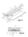
- the sealing member is intended for sealing an opening O of a surface S of a toner container TC (see figure 4 ) for laser printers, copy machines and fax machines, for example of a toner cartridge comprising a support for a magnetic roller or drum.
- the sealing member of figure 1 comprises :
- the wipping element W is for example made of a compressible, the wiping element comprising a first lateral portion W1 in compressed state and which is welded (heat, ultrasound, etc.) to the film 1, a second lateral portion W2 in compressed state and which is welded (heat, ultrasound, etc.) to the film 1, and a third portion W3 located between the first and second portions W1,W2.
- the first and second portions W1,W2 are welded to the film by means of three substantially parallel welding lines L1,L2,L3,L1',L2',L3'
- the welding lines L1,L1' are substantially parallel to the longitudinal direction LD of the central strip CS, which corresponds also to the pulling direction of the pulling means 3.
- a passage P is defined for the pulling means 3 and for the central strip CS after its tearing off.
- Said passage P has a width X greater than the width Y of the pulling means 3 and of the central strip CS, but lower than 1.2 times said width Y.
- the width Y of the central strip is defined between the two substantially parallel tearing lines CS3,CS4, which can be defined by weakening zones or grooves.
- the third portion W3 of the wiping element W has a face WS intended to contact the face 1A of the torn central strip CS during its tearing (face in contact with toner particles).
- the third portion W3 is less compressed in the middle L1' than in the portion adjacent to the welding L1,L1'
- the thickness is at least 20% lower than thickness of the middle portion of the wiping element W.
- the thickness of the middle portion of the wiping element W is at least 0.5 mm, advantageously at least 1 mm, for example 1 to 3 mm thicker than the welded portion.
- the thickness of the wiping element at the welding L1,L1' is less than 0.5mm, such as comprised between 0.1 and 0.4 mm, while the thickness of the middle portion is greater than 1 mm (for example comprised between 1.5 and 3 mm).
- a variation of compression state of the portion W3 is created between the welding lines L1,L1' whereby relative transverse strength RTS are created between the film and the wiping portion W3. This relative transverse strength RTS is appropriate for exerting some force tending to move or apply the middle portion of the wiping portion W3 towards the film 1, when the film is sealing the opening of the surface of the toner container.
- the welding lines L1,L1' from guiding means for the pulling means 3 and for the torn central strip CS.
- the guiding effect is even further improved due to the higher compression at the portions of the wiping element W_ adjacent to the welding lines L1, L1' whereby ensuring a higher wearing of the longitudinal edges of the pulling means 3 and of the torn central strip and whereby ensuring a better cleaning of the edge portion of the torn central strip CS, which are often the most difficult to be cleaned correctly.
- the higher compression state of the wiping element adjacent to the welding lines L1, L1' can also act as means for regulating or controlling the speed of the tearing operation, so as to ensure a sufficient contact between the wiping or cleaning element 3 and the face 1A of the central strip.
- transverse strength or tension is that after the full tearing of the central strip CS from the film 1, a force is tending to apply the face WS towards the film 1 and/or towards the surface of the container, in case the central strip has a portion extending under the wiping element. Such a force is advantageous so as to avoid that possible trapped toner particles could be released after the tearing of the central strip. Such a risk can also be prevented or avoided by using wiping element having absorbing properties or properties for attracting or attaching particles on or in the wiping element.
- the thickness of the wiping element can even be lower than 500 ⁇ m, such as lower than 300 ⁇ m, for example lower than 200 ⁇ m, while the degree of compression can be different as those specified.
- the wiping element can be the combination of a compressible material with a substantially non compressible material or layer, the latter being intended to contact the central strip to be cleaned.
- the sealing film I is provided on its face 1A with an adhesive layer 4 following substantially the edge of the film.
- Said adhesive layer 4 is before application of the sealing film on the surface to be sealed, provided with a removable siliconized paper 5, which is removed before gluing the film 1 on the surface to be sealed.
- the adhesive layer 4 is adapted for ensuring that at least the film portions 6,7 to which the cleaning element W is welded by the welding lines L1, L1', preferably by the welding lines L1,L2,L3, L1',L2',L3'. This is advantageous for ensuring that the film portion in contact with the wiping element is substantially static with respect to the surface S of the toner container. This is also advantageous for increasing the adhesion of said portions 6,7 with the surface, whereby preventing any risk of tearing of the wiping element during the tearing operation of the central portion.
- a cardboard support 8 is provided with adhering means. Said support is attached to the face 1B of the film, while not covering the wiping element W. Said cardboard is suitable for facilitating the placement of the sealing film 1 on the surface S to be sealed, after removal of the siliconized paper or protection sheet 5. Said support is removed after the placement of the sealing film 1.
- Figure 4 shows the placement of a sealing film 1 similar to the sealing film 1 of figure 1 .
- the sealing film is provided with a removable support 8 (such as in cardboard) having at least a portion supporting or rigidifying a portion of the sealing film 1, and at least portions (such as the arms 9) for supporting or rigidifying the welded portions W 1 ,W2 of the wiping element W.
- a removable support 8 such as in cardboard
- Figure 5 is an exploded view of a sealing member comprising a sealing film 1 and a slotted foam layer 10 attached to the face 1B of the sealing film 1.
- Two portions 10A.10B of the slotted foam layer are welded to the sealing film 1 (for example welding lines L1, L1'.
- An antiadhesive layer 11 is attached to the foam layer at the place where a passage P has to be formed between the foam layer 10 and the film 1, for the pulling means and/or the torn central strip CS.
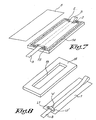
- Figures 7 and 8 show a slotted foam layer 12 having dimension greater than the dimension of the sealing film 1, whereby the slot 13 can be sealed or closed by the film 1.
- Glue or adhesive 14 is provided along the edges of the foam 12 for attaching said foam on the surface of the toner container to be sealed.
- the wiping element W is welded to the film 1 so that when the film 1 seals the slot 13, the wiping element is at least partly (preferably only partly) within the space defined by the slot 13 when the foam is not compressed.
- the film portions 6,7 ( Fig.3 ) which are welded to the wiping element W are provided with adhesive 15 for attaching said portions to the surface S of the container.
- Figures 9 to 11 show schematically the welding of a cleaning element W on a sealing film 1.
- the cleaning element W is made of an elastic and compressible material, such as an elastic sponge.
- the maximum elasticity can vary from a possible elastic stretching ST (with respect to the length LW in unstretched condition of the wiping element) of a few % (such as 5%, 10%, 20%, 30%, 50%, etc.) up to elastic stretching of more than 100%.
- the wiping element W is thus first stretched with respect to the sealing film 1 and is applied on the sealing film.
- Welding lines L1,L2,L3, L1', L2',L3' are then formed between the wiping element W and the film 1, so as to define a passage P.
- the element 17 is removed, so that when the film 1 is attached to the surface to be sealed, the film exerts a supplemental transversal stretching in the wiping element W.
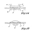
- a compressible element W is provided with a welding layer 29, which is contacted with the face 1B of the film 1.
- the welding layer 29 is used for making the welding zone 30, defining there between the passage P.
- the compressible element is made of a foam with open cells, whereby during the welding operation, part of the welding layer 29 is smelted so that material of the welding layer flows within the foam, so as to maintain in compressed state the foam at the welding zone 30.
- Figure 16 is a view of a sealing member similar to the sealing member of figure 1 , except that the cleaning element W is covered by a film 19 made of a material weldable to the film 1, for example the film 1 and the film 19 are made of the same material.
- the film 19 can for example be portions of waste strips obtained when cutting the film 1 with the pulling means in large film.
- the lateral portions of the film 19 are welded to the sealing film 1.
- the welding portions 6,7 of the film 1 are not provided with glue or adhesive 4 for attaching said portions 6,7 on the surface of the toner container to be sealed.
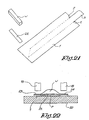
- the sealing film 1 is placed on a table 20 provided with a movable welding head 21 with a recess 22 defining a groove (the central portion of the recess has a greater depth that the edges of the recess).
- the pulling means 3 is place above the sealing film 1.
- the compressible material (such as a foam) W is placed above the pulling means 3 and the film 1.
- the film 19 is placed above the cleaning element W, and the welding head 21 is moved towards the table 20 (arrow Z), so as to compress the cleaning element W and so as to weld the films 1 and 19 together at the welding zones 6,7.
- the embodiment of figure 19 is similar to the embodiment of figure 16 , except that the sealing film 1 is associated to a slotted foam layer 10.
- the embodiment of figure 20 is similar to the embodiment of figure 19 , except that the wiping element W and the film 19 extend partly outside the sealing film 1.
- the sealing film I is first associated to an intermediate layer 22 for example made of a material compatible for making a welding between the film 1 and the layer 22 and a welding between the layer 22 and the foam W, said foam being not compatible as such for welding with the film 1.
- the foam is for example made in a thermoformable material, i.e. a shape can be given to the foam by heat treatment.
- the foam edges 23,24 are compressed and heated, whereby said edges are transformed in a sheet shape.
- a welding is also obtained between the intermediate layer 22 and the film 1 and between the intermediate layer 22 and the sheet shaped edges 23,24.
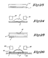
- Figures 23 and 24 show the preparation of a sealing member made from a film 1 and a wiping element W which are compatible for welding, for example by heat welding by welding head 18.
- the wiping element W is made of a compressible foam with open cells, said wiping element being placed between the sealing film 1 and a cover film 19 which are compatible for welding. During the movement of the welding head 18, the wiping element W is compressed and the films 1 and 19 are partly melted, whereby materials of said films flow into the compressed foam W, so as to form a welding extending in the foam.
- the wiping element W is first glued on the film 19. Thereafter the film 19 is welded to the sealing film 1.
- the embodiment of figure 29 is similar the embodiment of figure 1 , except that the wiping element W is attached to the sealing film by means of staples 30.
- the wiping element is provided with a covering sheet 31.
- the wiping element is made of compressible foam and is glued or not (preferably glued) along its lateral portions 32,33 on the sealing film 1.
- the staples 30 (for example two per lateral portions of the wiping element) ensure the compression of the foam at the lateral portions and make mechanical bonds between the sealing film 1, the lateral portions 32, 33 and the cover sheet 31.
- the use of a cover sheet 31 is advantageous for ensuring a good distribution of the compression force, as well as for ensuring a better bond for the foam material.
- the cover sheet act as a reinforcement element.
- the face 1B of the sealing film is provided with adhesive 4 for gluing the sealing film on a surface of a toner container.
- a removable cardboard support 8 is advantageously attached to the face 1 A for facilitating the placement of the sealing film. After placement of the film on the surface, the support 8 is then removed.
- the embodiment of figure 30 is similar to the embodiment of figure 29 , except that a slotted foam layer 10 is attached to the sealing film 1, and that the lateral portions 32,33 of the wiping element are covered by the cover sheet 31, the latter being covered by two legs 34 of the sealing film 1 which are folded on the cover sheet 31.
- the staples bind the legs, the cover sheet 31, the compressible foam W and the sealing film 1 together.
- the lateral portions 23,24 of the foam are rigidified.
- Two staples are shown for binding purposes. It is obvious that a greater number of staples can be used, such as three, four, five, etc. Even for specific case, a single staple is sufficient for binding a lateral portion of the wiping element with the sealing film.
- staples it is also possible to use other mechanical means, such as seams, for example by sewing different points, along one or several lines, etc. Sewing is quite advantageous as it enables to use material made of the same material than the sealing film.
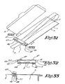
- the embodiment of figures 31-33 comprise a compressible foam bloc element 40 covered with a protection sheet 41.
- the protection sheet is glued on the foam element 40 (glue layer 44).
- the lateral portions 42 of the foam element are glued on the sealing film 1 (glue 45).
- the foam element is associated with two connecting elements 46 having a substantially U shape, said elements having each an upper blade 47 extending above the protection sheet 41 and ending with a pin entering the foam element 40, and a lower blade 48 extending below the sealing film 1.
- the blade 48 are not glued on the sealing film and are movable with respect to the sealing film 1.
- the blades 48 are placed under a surface of a protruding part 49 of the container, whereby compressing the foam portion comprised between the upper and lower blades.
- Figure 34 and 35 is a view of an toner cartridge which can be provided with elements 50 for ensuring a compression of the compressible foam bloc 51 glued along its lateral edges 52,53 to the sealing film 1, whereby the pulling means 3 extends between the glued edges of the foam 51 and between the foam 51 and the film 1.
- the toner cartridge comprises a container TC with a surface S provided with the opening O on which the sealing film is glued (glue layer 4), and a support 55 for a magnetic roller 56, with protruding surfaces 57.
- the elements 50 have a form adapted for clipping on a surface 57 of the support 55, and are advantageously connected the one to the other by a blade or rod 58 for ensuring a predetermined distance between the element 50.
- the elements have when placed on the support 55 a blade 59 forming a protrusion with respect to the surface 57 and directed towards the container TC.
- the support 55 provided with the elements 50 is placed above the container and is attached by clipping systems 60 or other means pressing the surface 57 towards the container.
- a toner cartridge is schematically shown.
- This toner cartridge comprises a toner container TC with a surface S with the opening O for the passage of toner, and a support 55 for a roller 56, said support having a surface 57 intended to be pressed towards the surface S.
- the toner container is provided with a blade 60 for example glued on the surface S, while the support 55 is also provided with a blade 61 for example glued on the surface 57.
- the sealing film 1 with the compressible foam W is placed on the toner container, so that the portion of the sealing film contacting the wiping foam W is at least partly above the blade 60.
- the support 55 is placed so that the blade 61 covers at least partly the wiping element W.
- the blades 60,61 have a length sufficient for extending partly outside the surfaces 57 and S.
- the ends 74 of the blades 60,61 are provided with a cut 64 defining two arms 65 provided with lateral teeth 66.
- the blades 60,61 are also provided with a central opening 67, with an open section lower than the upper section of the foam W.
- the pressing of the lateral portions of the wiping foam is obtained by connecting pieces 70 provided with an upper leg 71 adapted for contacting the surface 57 see for example fig 36 , an lower leg 72 adapted for contacting the surface S, and an opening 73 in the central portion 74 connecting the legs.
- the opening 73 is adapted for receiving one end 74 of the blade 60 and one end 74 of the blade 61.
- the teeth of the arms 65 and the cut 64 between two adjacent arms 65 are suitable for enabling to push the connecting pieces so that the arms 65 of the end of the blade 60, and the end of the blade 61 enter into the opening 73 of a connecting piece 70.
- the teeth are advantageously adapted for preventing any movement of the connecting piece away from the blades.
- a first blade is glued on the toner container, while the other is mounted rotatable with respect to said first blade, so that after pivoting the blade towards the first blade, the foam element is pressed between the two blades.
- a connecting piece possibly attached to one blade, is then sufficient for maintaining the pressing position of the blades for the foam.
Landscapes
- Physics & Mathematics (AREA)
- General Physics & Mathematics (AREA)
- Dry Development In Electrophotography (AREA)
- Electrophotography Configuration And Component (AREA)
- Cleaning In Electrography (AREA)
- Packages (AREA)
Claims (35)
- Verschlusselement zum Verschließen einer Öffnung (O) einer Oberfläche (S) eines Tonerbehälters (TC) für Laserdrucker, Kopiergeräte und Faxgeräte, wobei das Verschlusselement umfasst:• eine Verschlussfolie (1) mit einer ersten Fläche (1A), die in Richtung der Oberfläche (S) gerichtet sein soll, um die Öffnung (O) des Tonerbehälters (TC) zu verschließen, und eine zweite Fläche (1B), die der ersten Fläche (1A) gegenüberliegt, wobei die Folie (1) einen längslaufenden Mittelstreifen (CS) umfasst, der zum Abreißen gedacht ist, wobei sich der Mittelstreifen von einem ersten Ende (CS1) zu einem zweiten Ende (CS2) erstreckt und eine im Wesentlichen vorbestimmte Breite (Y) aufweist,• ein Abwisch- oder Reinigungselement (W) zum Abwischen des Bereiches der ersten Fläche (1A) der Verschlussfolie (1) entsprechend dem Mittelstreifen (CS), wenn der abgerissene Mittelstreifen mit dem Abwischelement (W) in Berührung kommt,• ein an das erste Ende (CS1) des Mittelstreifens (CS) gebundenes Zugelement (3), wobei sich das Zugelement (3) vor dem Abziehen von dem Mittelstreifen (CS) mindestens teilweise über die zweite Fläche (1B) der Verschlussfolie (1) ausdehnen soll,in der das Abwischelement (W) an einer Komponente angebracht ist, ausgewählt aus der Gruppe, bestehend aus der Verschlussfolie (1), einer an der Verschlussfolie (1) angebrachten Schaumschicht, einer an der Verschlussfolie (1) angebrachten Nichtschaumhalterung und Kombinationen davon, durch mindestens ein Verbindungsmittel, ausgewählt aus der Gruppe, bestehend aus:- der Kombination aus mindestens einer ersten Schweißung (L1) und einer zweiten Schweißung (L1'),- einem Verbindungselement (22), das durch eine erste Schweißung und eine zweite Schweißung an der Komponente angebracht ist,- zwei verschiedene Verbindungselemente, von denen ein erstes durch eine erste Schweißung an der Komponente angebracht ist, während das zweite durch eine zweite Schweißung an der Komponente angebracht ist,- zwei verschiedene Verbindungselemente, von denen ein erstes durch eine erste Schweißung an einer ersten Komponente angebracht ist, während die zweite durch eine zweite Schweißung an einer anderen Komponente angebracht ist, und- Kombinationen davon,wobei die erste Schweißung (L1) und die zweite Schweißung (L1') so voneinander entfernt sind, dass sie dazwischen einen Durchlass (P) für den abgerissenen Mittelstreifen (CS) definieren und/oder wobei ein Durchlass (P) zwischen den Seitenabschnitten (32, 33) des Abwischelements (W) und zwischen dem Mittelabschnitt des Abwischelements (W) und der Komponente definiert wird.
- Verschlusselement nach Anspruch 1, in dem das Abwischelement (W) einen ersten Abschnitt (W1) und einen zweiten Abschnitt (W2) aufweist, die an die Komponente geschweißt sind, um zwischen den Abschnitten (W1, W2) einen Durchlass (P) zu definieren mit einer Breite (X), die im Wesentlichen der vorbestimmten Breite (Y) des Mittelstreifens (CS) entspricht.
- Verschlusselement nach Anspruch 1, das mit einem Mittel (L1, L1') versehen ist, um mindestens eine relative Querspannung zwischen der Komponente und dem Abwischelement (W) zu erzeugen, wenn die Verschlussfolie die Öffnung (O) des Tonerbehälters (TC) verschließt.
- Verschlusselement nach Anspruch 1, in dem das Abwischelement (W) durch mindestens zwei Schweißnähte (L1, L1') an der Komponente angebracht ist, wobei die Schweißnähte (L1, L1') Führungsmittel für den abgerissenen Mittelstreifen (CS) während des Abreißens bilden.
- Verschlusselement nach Anspruch 1, in dem das Abwischelement (W) aus einem Material besteht, ausgewählt aus der Gruppe, bestehend aus schweißbaren Materialien, Materialien, die mit mindestens einer schweißbaren Schicht versehen sind, in Lösungsmittel lösliche Materialien, Materialien mit einer in Lösungsmitteln löslichen Schicht, reagierende Materialien und Materialien mit einer reaktiven Schicht.
- Verschlusselement nach Anspruch 1, in dem die Verschlussfolie (1) aus schweißbaren Materialien, aus Materialien mit mindestens einer schweißbaren Schicht, in Lösungsmitteln löslichen Materialien, Materialien mit einer in Lösungsmitteln löslichen Schicht, reagierenden Materialien und Materialien mit einer reaktiven Schicht besteht.
- Verschlusselement nach Anspruch 1, in dem das Abwischelement (W) aus einem komprimierbaren Material besteht, wobei das Abwischelement einen ersten Abwischabschnitt aufweist, der an die erste Schweißung (L1) grenzt, und einen zweiten Abwischabschnitt, der an die zweite Schweißung (L1') grenzt, wodurch der erste und der zweite Abwischabschnitt komprimiert werden.
- Verschlusselement nach Anspruch 7, in dem das Abwischelement (W) einen dritten Abwischabschnitt (W3) umfasst, der sich zwischen dem ersten und dem zweiten Abwischabschnitt befindet, wobei der dritte Abwischabschnitt (W3) in Bezug auf den ersten und den zweiten Abwischabschnitt weniger komprimiert wird.
- Verschlusselement nach Anspruch 1, in dem das Abwischelement (W) eine komprimierbare Schaumschicht umfasst, wobei die Schaumschicht einen ersten Abschnitt und einen zweiten Abschnitt aufweist, die in einem komprimierten Zustand an die Verschlussfolie (1) geschweißt sind.
- Verschlusselement nach Anspruch 1, in dem die Verschlussfolie (1) und das Abwischelement (W) miteinander verschweißt sind und aus kompatiblen thermoplastischen Materialien bestehen.
- Verschlusselement nach Anspruch 1, in dem die erste Fläche (1A) der Verschlussfolie (1) mit einer Haftschicht (4) versehen ist, um die Verschlussfolie (1) an die Oberfläche (S) des zu verschließenden Behälters (TC) anzubringen, wodurch mindestens die erste Fläche der Abschnitte (6, 7) der Folie (1), die durch die erste Schweißung (L1) und die zweite Schwei-ßung (L1') an das Abwischelement (W) angebracht sind, mit einem Haftmittel zum Anbringen der Abschnitte (6, 7) an die Oberfläche (S) des zu verschließenden Behälters (TC) versehen sind.
- Verschlusselement nach Anspruch 1, in dem die erste Fläche (1A) der Verschlussfolie (1) mit einer Haftschicht (4) versehen ist, um die Verschlussfolie (1) an die Oberfläche (S) des zu verschließenden Behälters (TC) anzubringen, wodurch mindestens die erste Fläche der Abschnitte (6, 7) der Folie (1), die durch die erste Schweißung (L1) und die zweite Schweißung (L1') an das Abwischelement (W) angebracht sind, teilweise nicht mit einem Haftmittel zum Anbringen der Abschnitte (6, 7) an die Oberfläche (S) des zu verschließenden Behälters (TC) versehen sind.
- Verschlusselement nach Anspruch 1, in dem das Abwischelement (W) ausgewählt ist aus der Gruppe, bestehend aus Schaumelement, Abwischeinrichtung, Filz, antistatischer Schicht, Reibung verringernder Schicht, Material, das ein Reibung reduzierendes Mittel abgibt, Material, das ein antistatisches Mittel abgibt, abgebender Schicht, Magnetmaterial und Kombinationen davon.
- Verschlusselement nach Anspruch 1, in dem die erste und zweite Schweißung (L1. L1') ausgewählt werden aus der Gruppe, bestehend aus Warmschweißen, Kaltschweißen, reaktivem Schweißen, Lösungsmittelschweißen und Kombinationen davon.
- Verschlusselement nach Anspruch 1, in dem die Verschlussfolie (1) mit einem Klebemittel (4) versehen ist, um die Verschlussfolie (1) an der Oberfläche des Behälters (TC) mit der zu verschließenden Öffnung anzubringen.
- Verschlusselement nach Anspruch 1, in dem die Verschlussfolie (1) mit mindestens einem Schaumelement (12) versehen ist.
- Verschlusselement nach Anspruch 1, in dem die Verschlussfolie (1) mit mindestens einem Schaumelement (12) versehen ist, wobei das Schaumelement (12) mit Klebemittel (14) versehen ist, um das Verschlusselement an die Oberfläche (S) des Behälters (TC) mit der zu verschließenden Öffnung anzubringen.
- Verschlusselement nach Anspruch 1, in dem der abgerissene Mittelstreifen (CS) zwei im Wesentlichen parallele Längskanten (CS3, CS4) aufweist, die dazwischen eine Breite definieren, und in denen die erste und die zweite Schweißung (L1, L1') voneinander beabstandet sind, wobei der Abstand weniger als 120% der Breite des Mittelstreifens (CS) entspricht.
- Verschlusselement nach Anspruch 1, in dem die erste Schweißung (L1) und die zweite Schweißung (L1') im Wesentlichen parallele Schweißnähte sind.
- Verschlusselement nach Anspruch 1, das mit einem Mittel (L1, L1', 30) verbunden wurde, um mindestens eine Querspannung des Abwischelements (W) zu gewährleisten, wenn die Verschlussfolie (1) die Öffnung (O) des Tonerbehälters (TC) verschließt.
- Verschlusselement nach Anspruch 1, in dem die erste und zweite Schweißung (L1, L1') Schweißungen zwischen der Verschlussfolie und den Zwischenelementen sind, die an den Abwischelementen gebunden sind.
- Verschlusselement nach Anspruch 1, das ferner mit mindestens einem Haltemittel (8) versehen ist, um die Platzierung des Verschlusselements (1) zu vereinfachen.
- Verschlusselement nach Anspruch 1, das ferner mit mindestens einer Papphalterung (8) versehen ist, um die Platzierung des Verschlusselements zu erleichtern, wobei die Papphalterung an der zweiten Fläche (1B) der Verschlussfolie (1) angebracht ist.
- Verschlusselement nach Anspruch 1, in dem sich das Abwischelement (W) mindestens teilweise außen an der Verschlussfolie (1) erstreckt.
- Verschlusselement nach Anspruch 1, in dem das Abwischelement (W) mindestens teilweise von einem Verbindungselement abgedeckt ist, das durch eine erste Schweißung (L1) und durch eine zweite Schweißung (L1') an der Verschlussfolie (1) angebracht ist, welche voneinander beabstandet sind, um dazwischen einen Durchlass (P) für den abgerissenen Mittelstreifen (CS) zu definieren.
- Verschlusselement nach Anspruch 1, in dem das Verbindungselement ausgewählt ist aus der Gruppe, bestehend aus Folien (22), die an die Verschlussfolie schweißbar sind, und Schichten, die an das Abwischelement gebunden und an die Verschlussfolie schweißbar sind.
- Verschlusselement nach Anspruch 1, in dem das Abwischelement (W) mindestens teilweise von einer schweißbaren Folie (19) bedeckt ist, wobei die Folie einen ersten Abschnitt und einen zweiten Abschnitt aufweist, die an die Verschlussfolie (1) geschweißt sind, um zwischen diesen Abschnitten einen Durchlass (P) zu definieren mit einer Breite (X), die mindestens im Wesentlichen der vorbestimmten Breite (Y) des Mittelstreifens (CS) entspricht.
- Verschlusselement nach Anspruch 1, in dem das Abwischelement (W) von einer Folie (19) mit zwei beabstandeten Abschnitten bedeckt ist, welche die Verschlussfolie (1) berühren und an die Verschlussfolie (1) geschweißt sind, und in dem die Verschlussfolie aus schweißbaren Materialien, Materialien mit mindestens einer schweißbaren Schicht, in Lösungsmitteln löslichen Materialien, Materialien mit einer in Lösungsmitteln löslichen Schicht, reagierenden Materialien und Materialien mit einer reaktiven Schicht besteht.
- Verschlusselement nach Anspruch 1, in dem das Verbindungsmittel einen Druck zwischen den Seitenabschnitten des Abwischelements und der Komponente ausübt, der ausreichend ist, um Führungsmittel für den abgerissenen Mittelstreifen während seines Abreißens.
- Verschlusselement nach Anspruch 1, in dem das Verbindungsmittel (L1, L1') einen Druck zwischen den Seitenabschnitten des Abwischelements und der Komponente ausübt, der größer ist als der Druck des Mittelabschnitts (W3) des Abwischelements (W) und der Komponente (1).
- Verschlusselement nach Anspruch 1, in dem das Verbindungsmittel angepasst ist, um das Abreißen des Abwischelements während des Abreißens des Mittelstreifens zu verhindern.
- Verschlusselement nach Anspruch 1, in dem das Abwischelement (W) mindestens teilweise von einem Folienelement (19) abgedeckt ist.
- Verschlusselement nach Anspruch 1, in dem das Verbindungsmittel ein mechanisches Mittel (46, 47) ist, das mindestens zwischen den Seitenabschnitten des Abwischelements und der Komponente wirkt.
- Verschlusselement nach Anspruch 1, in dem das Verbindungsmittel (L1, L1', 30) angepasst ist, um einen Druck zwischen den Seitenabschnitten des Abwischelements und der Komponente auszuüben, die ausreichend ist, um ein Führungsmittel für den abgerissenen Mittelstreifen während seines Abreißens zu bilden.
- Tonerbehälter (TC) für Laserdrucker, Kopiergeräte und Faxgeräte, wobei der Tonerbehälter eine Oberfläche (S) mit einer Öffnung für den Durchlass des Toners aufweist, wobei der Tonerbehälter (TC) mit einem Verschlusselement gemäß einem der vorangegangenen Ansprüche versehen ist, um die Öffnung zu verschließen.
Applications Claiming Priority (3)
| Application Number | Priority Date | Filing Date | Title |
|---|---|---|---|
| US197240 | 2002-07-16 | ||
| US10/197,240 US6760556B2 (en) | 2002-07-16 | 2002-07-16 | Sealing member and toner container provided with such a sealing member |
| PCT/BE2003/000119 WO2004007297A2 (en) | 2002-07-16 | 2003-07-04 | Sealing member and toner container provided with such a sealing member |
Publications (2)
| Publication Number | Publication Date |
|---|---|
| EP1521999A2 EP1521999A2 (de) | 2005-04-13 |
| EP1521999B1 true EP1521999B1 (de) | 2008-04-16 |
Family
ID=30115125
Family Applications (1)
| Application Number | Title | Priority Date | Filing Date |
|---|---|---|---|
| EP03763520A Expired - Lifetime EP1521999B1 (de) | 2002-07-16 | 2003-07-04 | Verschlussteil und damit versehener tonerbehälter |
Country Status (6)
| Country | Link |
|---|---|
| US (1) | US6760556B2 (de) |
| EP (1) | EP1521999B1 (de) |
| AT (1) | ATE392649T1 (de) |
| AU (1) | AU2003243848A1 (de) |
| DE (1) | DE60320412D1 (de) |
| WO (1) | WO2004007297A2 (de) |
Families Citing this family (14)
| Publication number | Priority date | Publication date | Assignee | Title |
|---|---|---|---|---|
| US7212765B2 (en) * | 2002-03-05 | 2007-05-01 | Static Control Components, Inc. | Systems and methods for remanufacturing imaging components |
| US6993265B2 (en) * | 2003-10-07 | 2006-01-31 | Dataproducts U.S.A., Llc | Seal for toner cartridge assembly |
| US20060198656A1 (en) * | 2005-03-04 | 2006-09-07 | Static Control Components, Inc. | Toner cartridge seal assembly |
| US7197260B2 (en) * | 2005-03-09 | 2007-03-27 | Static Contron Components, Inc. | Toner cartridge seal assembly |
| AT502051B1 (de) * | 2005-05-06 | 2007-01-15 | Marco Ing Ueberall | Verschlusseinrichtung für tonerbehälter und tonerbehälter mit einer derartigen verschlusseinrichtung |
| US7257363B2 (en) * | 2005-09-22 | 2007-08-14 | Lexmark International, Inc. | Device for moving toner within an image forming device |
| JP5187114B2 (ja) * | 2008-02-25 | 2013-04-24 | 株式会社リコー | 現像装置、プロセスカートリッジおよび画像形成装置 |
| US8005395B2 (en) * | 2008-03-25 | 2011-08-23 | Static Control Components, Inc. | Universal cartridge seal and method for fixing the seal to a cartridge |
| JP4609548B2 (ja) * | 2008-08-20 | 2011-01-12 | 富士ゼロックス株式会社 | 現像装置、プロセスカートリッジ、画像形成装置及び現像剤収容器 |
| JP5636652B2 (ja) * | 2009-08-21 | 2014-12-10 | 富士ゼロックス株式会社 | 分級装置及び分級方法 |
| JP5757079B2 (ja) * | 2010-10-21 | 2015-07-29 | 株式会社リコー | 粉体収容器、粉体搬送装置及び画像形成装置 |
| JP2014056045A (ja) * | 2012-09-11 | 2014-03-27 | Canon Inc | 現像剤収納ユニット、プロセスカートリッジ、電子写真画像形成装置 |
| US20140089207A1 (en) * | 2012-09-27 | 2014-03-27 | Oracle International Corporation | System and method for providing high level view tracking of changes in sca artifacts |
| CN206067049U (zh) | 2016-07-29 | 2017-04-05 | 合肥鑫晟光电科技有限公司 | 膜材以及撕膜装置 |
Family Cites Families (19)
| Publication number | Priority date | Publication date | Assignee | Title |
|---|---|---|---|---|
| US3390901A (en) | 1967-02-27 | 1968-07-02 | Gen Electric | Quick disconnect flangeless waveguide coupling |
| US4062385A (en) * | 1975-03-14 | 1977-12-13 | Eastman Kodak Company | Toner handling apparatus |
| JPH0228673A (ja) | 1988-07-18 | 1990-01-30 | Minolta Camera Co Ltd | 現像剤容器 |
| JPH046046A (ja) | 1990-04-11 | 1992-01-10 | Kaito Kagaku Kogyo Kk | 易開封性密封袋およびその製造方法並びに易開封性密封袋用包装材料およびその製造方法 |
| US5110646A (en) | 1991-01-25 | 1992-05-05 | James D. Prestel | Process and materials for reconditioning a toner cartridge |
| JP2989028B2 (ja) * | 1991-03-20 | 1999-12-13 | キヤノン株式会社 | 現像剤容器 |
| JP3165729B2 (ja) * | 1992-03-23 | 2001-05-14 | キヤノン株式会社 | 現像装置及びプロセスカートリッジ |
| JPH06242675A (ja) * | 1993-02-17 | 1994-09-02 | Ricoh Co Ltd | トナー補給容器 |
| GB2286062B (en) | 1994-01-19 | 1998-04-01 | Xerox Corp | Cartridge sealing strip cleaning |
| GB2289238B (en) | 1994-05-11 | 1998-08-26 | Kesel Jan De | Seal for a toner cartridge assembly |
| US5523828A (en) | 1994-09-14 | 1996-06-04 | De Kesel; Jan | Seal for a toner cartridge assembly |
| JP2987083B2 (ja) * | 1994-10-21 | 1999-12-06 | 株式会社リコー | トナーカートリッジ |
| JP3776958B2 (ja) | 1995-09-11 | 2006-05-24 | 大日本印刷株式会社 | トナー容器用蓋材フィルム及びトナー容器 |
| BE1010055A4 (nl) | 1996-03-01 | 1997-12-02 | Kesel Jan De | Middel voor inktbak. |
| US6585359B1 (en) | 1997-06-04 | 2003-07-01 | Hewlett-Packard Development Company, L.P. | Ink container providing pressurized ink with ink level sensor |
| SI1180378T1 (sl) | 1999-03-03 | 2011-04-29 | Optinose As | Nazalni aplikator |
| AU1682601A (en) * | 1999-12-03 | 2001-06-12 | Gino Sirejacob | Toner assembly |
| US20010033909A1 (en) | 2000-03-07 | 2001-10-25 | Cornelius Lester E. | Reinforced toner seal tear strip construction |
| JP2002040780A (ja) | 2000-07-27 | 2002-02-06 | Canon Inc | トナーシール及びトナー収納容器及び現像カートリッジ及びプロセスカートリッジ |
-
2002
- 2002-07-16 US US10/197,240 patent/US6760556B2/en not_active Expired - Fee Related
-
2003
- 2003-07-04 WO PCT/BE2003/000119 patent/WO2004007297A2/en not_active Ceased
- 2003-07-04 AU AU2003243848A patent/AU2003243848A1/en not_active Abandoned
- 2003-07-04 AT AT03763520T patent/ATE392649T1/de not_active IP Right Cessation
- 2003-07-04 DE DE60320412T patent/DE60320412D1/de not_active Expired - Lifetime
- 2003-07-04 EP EP03763520A patent/EP1521999B1/de not_active Expired - Lifetime
Also Published As
| Publication number | Publication date |
|---|---|
| AU2003243848A1 (en) | 2004-02-02 |
| ATE392649T1 (de) | 2008-05-15 |
| WO2004007297A2 (en) | 2004-01-22 |
| EP1521999A2 (de) | 2005-04-13 |
| US6760556B2 (en) | 2004-07-06 |
| AU2003243848A8 (en) | 2004-02-02 |
| DE60320412D1 (de) | 2008-05-29 |
| US20040013444A1 (en) | 2004-01-22 |
| WO2004007297A3 (en) | 2004-11-11 |
Similar Documents
| Publication | Publication Date | Title |
|---|---|---|
| US6760556B2 (en) | Sealing member and toner container provided with such a sealing member | |
| US4410575A (en) | Lap welding method for textile fabrics | |
| EP0774229B1 (de) | Einweg Wischgegenstand | |
| RU2245947C2 (ru) | Способ термосварки и термосварочное устройство для волокнистых листовых материалов | |
| JP3628171B2 (ja) | 清掃用モップ | |
| NZ205183A (en) | Wiping cloth includes a liquid"active material" | |
| JPS594699B2 (ja) | 静電複写装置内の融着材料の表面を処理する方法 | |
| CA2369254C (en) | Disposable wipe-out sheet and process for making the same | |
| CA1114885A (en) | Wick for dispensing fuser oil | |
| JPS594701B2 (ja) | 静電複写装置内の融着部材の表面を処理する方法 | |
| HK1043929A1 (en) | Disposable wipe-out sheet and process for making the same | |
| US5930559A (en) | Means for the sealing of a toner cartridge | |
| JPS58501679A (ja) | スプライスしたウエブとスプライス形成方法 | |
| CA1155954A (en) | Recording diskette having flocked-fiber wiping fabric | |
| EP0175753A1 (de) | Stossabsorbierende schützanlage. | |
| CA2296368A1 (en) | Elongated liquid absorbent pad and system for collecting leaks and spills | |
| WO1992004990A1 (en) | Article and method for cleaning printers and copiers | |
| KR20180107798A (ko) | 액상 및 파우더 화장품 겸용 퍼프 및 이의 제조방법 | |
| US20030152399A1 (en) | Sealing member for toner cartridge | |
| CN118105019A (zh) | 清扫用片、清扫用片的层叠体、清扫工具和清扫用片的制造方法 | |
| JP5102942B2 (ja) | 写真画像形成プロセス用などのフェルト材 | |
| US6778793B2 (en) | Sealing member for toner cartridge | |
| JPH0614858A (ja) | 清掃用物品 | |
| JPH08690Y2 (ja) | 定着ロール用クリーニング装置 | |
| JPH0727307B2 (ja) | クリーニングシート |
Legal Events
| Date | Code | Title | Description |
|---|---|---|---|
| PUAI | Public reference made under article 153(3) epc to a published international application that has entered the european phase |
Free format text: ORIGINAL CODE: 0009012 |
|
| 17P | Request for examination filed |
Effective date: 20050118 |
|
| AK | Designated contracting states |
Kind code of ref document: A2 Designated state(s): AT BE BG CH CY CZ DE DK EE ES FI FR GB GR HU IE IT LI LU MC NL PT RO SE SI SK TR |
|
| AX | Request for extension of the european patent |
Extension state: AL LT LV MK |
|
| DAX | Request for extension of the european patent (deleted) | ||
| 17Q | First examination report despatched |
Effective date: 20061026 |
|
| GRAP | Despatch of communication of intention to grant a patent |
Free format text: ORIGINAL CODE: EPIDOSNIGR1 |
|
| GRAS | Grant fee paid |
Free format text: ORIGINAL CODE: EPIDOSNIGR3 |
|
| GRAA | (expected) grant |
Free format text: ORIGINAL CODE: 0009210 |
|
| AK | Designated contracting states |
Kind code of ref document: B1 Designated state(s): AT BE BG CH CY CZ DE DK EE ES FI FR GB GR HU IE IT LI LU MC NL PT RO SE SI SK TR |
|
| REG | Reference to a national code |
Ref country code: CH Ref legal event code: EP |
|
| REG | Reference to a national code |
Ref country code: IE Ref legal event code: FG4D |
|
| REF | Corresponds to: |
Ref document number: 60320412 Country of ref document: DE Date of ref document: 20080529 Kind code of ref document: P |
|
| PG25 | Lapsed in a contracting state [announced via postgrant information from national office to epo] |
Ref country code: SI Free format text: LAPSE BECAUSE OF FAILURE TO SUBMIT A TRANSLATION OF THE DESCRIPTION OR TO PAY THE FEE WITHIN THE PRESCRIBED TIME-LIMIT Effective date: 20080416 |
|
| NLV1 | Nl: lapsed or annulled due to failure to fulfill the requirements of art. 29p and 29m of the patents act | ||
| PG25 | Lapsed in a contracting state [announced via postgrant information from national office to epo] |
Ref country code: NL Free format text: LAPSE BECAUSE OF FAILURE TO SUBMIT A TRANSLATION OF THE DESCRIPTION OR TO PAY THE FEE WITHIN THE PRESCRIBED TIME-LIMIT Effective date: 20080416 Ref country code: ES Free format text: LAPSE BECAUSE OF FAILURE TO SUBMIT A TRANSLATION OF THE DESCRIPTION OR TO PAY THE FEE WITHIN THE PRESCRIBED TIME-LIMIT Effective date: 20080727 Ref country code: FI Free format text: LAPSE BECAUSE OF FAILURE TO SUBMIT A TRANSLATION OF THE DESCRIPTION OR TO PAY THE FEE WITHIN THE PRESCRIBED TIME-LIMIT Effective date: 20080416 Ref country code: PT Free format text: LAPSE BECAUSE OF FAILURE TO SUBMIT A TRANSLATION OF THE DESCRIPTION OR TO PAY THE FEE WITHIN THE PRESCRIBED TIME-LIMIT Effective date: 20080916 Ref country code: BG Free format text: LAPSE BECAUSE OF FAILURE TO SUBMIT A TRANSLATION OF THE DESCRIPTION OR TO PAY THE FEE WITHIN THE PRESCRIBED TIME-LIMIT Effective date: 20080716 |
|
| PG25 | Lapsed in a contracting state [announced via postgrant information from national office to epo] |
Ref country code: AT Free format text: LAPSE BECAUSE OF FAILURE TO SUBMIT A TRANSLATION OF THE DESCRIPTION OR TO PAY THE FEE WITHIN THE PRESCRIBED TIME-LIMIT Effective date: 20080416 |
|
| PG25 | Lapsed in a contracting state [announced via postgrant information from national office to epo] |
Ref country code: SE Free format text: LAPSE BECAUSE OF FAILURE TO SUBMIT A TRANSLATION OF THE DESCRIPTION OR TO PAY THE FEE WITHIN THE PRESCRIBED TIME-LIMIT Effective date: 20080716 Ref country code: DE Free format text: LAPSE BECAUSE OF FAILURE TO SUBMIT A TRANSLATION OF THE DESCRIPTION OR TO PAY THE FEE WITHIN THE PRESCRIBED TIME-LIMIT Effective date: 20080717 Ref country code: CZ Free format text: LAPSE BECAUSE OF FAILURE TO SUBMIT A TRANSLATION OF THE DESCRIPTION OR TO PAY THE FEE WITHIN THE PRESCRIBED TIME-LIMIT Effective date: 20080416 Ref country code: DK Free format text: LAPSE BECAUSE OF FAILURE TO SUBMIT A TRANSLATION OF THE DESCRIPTION OR TO PAY THE FEE WITHIN THE PRESCRIBED TIME-LIMIT Effective date: 20080416 |
|
| PLBE | No opposition filed within time limit |
Free format text: ORIGINAL CODE: 0009261 |
|
| STAA | Information on the status of an ep patent application or granted ep patent |
Free format text: STATUS: NO OPPOSITION FILED WITHIN TIME LIMIT |
|
| EN | Fr: translation not filed | ||
| PG25 | Lapsed in a contracting state [announced via postgrant information from national office to epo] |
Ref country code: RO Free format text: LAPSE BECAUSE OF FAILURE TO SUBMIT A TRANSLATION OF THE DESCRIPTION OR TO PAY THE FEE WITHIN THE PRESCRIBED TIME-LIMIT Effective date: 20080416 Ref country code: BE Free format text: LAPSE BECAUSE OF FAILURE TO SUBMIT A TRANSLATION OF THE DESCRIPTION OR TO PAY THE FEE WITHIN THE PRESCRIBED TIME-LIMIT Effective date: 20080416 Ref country code: SK Free format text: LAPSE BECAUSE OF FAILURE TO SUBMIT A TRANSLATION OF THE DESCRIPTION OR TO PAY THE FEE WITHIN THE PRESCRIBED TIME-LIMIT Effective date: 20080416 |
|
| REG | Reference to a national code |
Ref country code: CH Ref legal event code: PL |
|
| 26N | No opposition filed |
Effective date: 20090119 |
|
| PG25 | Lapsed in a contracting state [announced via postgrant information from national office to epo] |
Ref country code: MC Free format text: LAPSE BECAUSE OF NON-PAYMENT OF DUE FEES Effective date: 20080731 |
|
| PG25 | Lapsed in a contracting state [announced via postgrant information from national office to epo] |
Ref country code: EE Free format text: LAPSE BECAUSE OF FAILURE TO SUBMIT A TRANSLATION OF THE DESCRIPTION OR TO PAY THE FEE WITHIN THE PRESCRIBED TIME-LIMIT Effective date: 20080416 |
|
| PG25 | Lapsed in a contracting state [announced via postgrant information from national office to epo] |
Ref country code: CH Free format text: LAPSE BECAUSE OF NON-PAYMENT OF DUE FEES Effective date: 20080731 Ref country code: LI Free format text: LAPSE BECAUSE OF NON-PAYMENT OF DUE FEES Effective date: 20080731 |
|
| PG25 | Lapsed in a contracting state [announced via postgrant information from national office to epo] |
Ref country code: IE Free format text: LAPSE BECAUSE OF NON-PAYMENT OF DUE FEES Effective date: 20080704 |
|
| PG25 | Lapsed in a contracting state [announced via postgrant information from national office to epo] |
Ref country code: IT Free format text: LAPSE BECAUSE OF FAILURE TO SUBMIT A TRANSLATION OF THE DESCRIPTION OR TO PAY THE FEE WITHIN THE PRESCRIBED TIME-LIMIT Effective date: 20080416 |
|
| PG25 | Lapsed in a contracting state [announced via postgrant information from national office to epo] |
Ref country code: CY Free format text: LAPSE BECAUSE OF FAILURE TO SUBMIT A TRANSLATION OF THE DESCRIPTION OR TO PAY THE FEE WITHIN THE PRESCRIBED TIME-LIMIT Effective date: 20080416 |
|
| PGFP | Annual fee paid to national office [announced via postgrant information from national office to epo] |
Ref country code: GB Payment date: 20090720 Year of fee payment: 7 |
|
| PG25 | Lapsed in a contracting state [announced via postgrant information from national office to epo] |
Ref country code: LU Free format text: LAPSE BECAUSE OF NON-PAYMENT OF DUE FEES Effective date: 20080704 Ref country code: HU Free format text: LAPSE BECAUSE OF FAILURE TO SUBMIT A TRANSLATION OF THE DESCRIPTION OR TO PAY THE FEE WITHIN THE PRESCRIBED TIME-LIMIT Effective date: 20081017 |
|
| PG25 | Lapsed in a contracting state [announced via postgrant information from national office to epo] |
Ref country code: TR Free format text: LAPSE BECAUSE OF FAILURE TO SUBMIT A TRANSLATION OF THE DESCRIPTION OR TO PAY THE FEE WITHIN THE PRESCRIBED TIME-LIMIT Effective date: 20080416 |
|
| PG25 | Lapsed in a contracting state [announced via postgrant information from national office to epo] |
Ref country code: GR Free format text: LAPSE BECAUSE OF FAILURE TO SUBMIT A TRANSLATION OF THE DESCRIPTION OR TO PAY THE FEE WITHIN THE PRESCRIBED TIME-LIMIT Effective date: 20080717 |
|
| GBPC | Gb: european patent ceased through non-payment of renewal fee |
Effective date: 20100704 |
|
| PG25 | Lapsed in a contracting state [announced via postgrant information from national office to epo] |
Ref country code: GB Free format text: LAPSE BECAUSE OF NON-PAYMENT OF DUE FEES Effective date: 20100704 |
|
| PG25 | Lapsed in a contracting state [announced via postgrant information from national office to epo] |
Ref country code: FR Free format text: LAPSE BECAUSE OF FAILURE TO SUBMIT A TRANSLATION OF THE DESCRIPTION OR TO PAY THE FEE WITHIN THE PRESCRIBED TIME-LIMIT Effective date: 20090227 |