EP1524675A1 - Vorrichtung zur Verschiebung von Teilchen - Google Patents
Vorrichtung zur Verschiebung von Teilchen Download PDFInfo
- Publication number
- EP1524675A1 EP1524675A1 EP04104982A EP04104982A EP1524675A1 EP 1524675 A1 EP1524675 A1 EP 1524675A1 EP 04104982 A EP04104982 A EP 04104982A EP 04104982 A EP04104982 A EP 04104982A EP 1524675 A1 EP1524675 A1 EP 1524675A1
- Authority
- EP
- European Patent Office
- Prior art keywords
- neff
- network
- substrate
- index
- waveguide
- Prior art date
- Legal status (The legal status is an assumption and is not a legal conclusion. Google has not performed a legal analysis and makes no representation as to the accuracy of the status listed.)
- Granted
Links
Images


Classifications
-
- G—PHYSICS
- G21—NUCLEAR PHYSICS; NUCLEAR ENGINEERING
- G21K—HANDLING OF PARTICLES OR IONISING RADIATION NOT OTHERWISE PROVIDED FOR; IRRADIATION DEVICES; GAMMA RAY OR X-RAY MICROSCOPES
- G21K1/00—Arrangements for handling particles or ionising radiation, e.g. focusing or moderating
- G21K1/30—Arrangements for handling particles or ionising radiation, e.g. focusing or moderating for confining neutral particles or handling confined neutral particles, e.g. atom traps
Definitions
- the invention relates to the field of techniques of movement and manipulation of particles by optical forces.
- the applications envisaged are the displacement without contact, particles (balls of different materials, nano-objects, cells or other biological objects) over great distances (several centimeters) and with trajectories predefined.
- particles balls of different materials, nano-objects, cells or other biological objects
- trajectories predefined.
- This method poses difficulties in entrapment, in particular of nanometric particles. he takes at least several seconds to trap, by for example, a gold particle of 36 nm in diameter.
- This technique allows to collect, above of a guide, scattered particles randomly (thanks to the gradient forces) and then move these particles along the guide (forces of diffusion).
- the method also applies to particles metal but has the disadvantage of being very dependent on the surface condition of the guide: roughness important manages to permanently stop the particle.
- the invention uses forces optical generated by a diffraction grating.
- the displacement forces of the particle are generated by light diffraction network and are oriented according to characteristics of the network.
- the network is used as an element that decouples the light that propagates in a guide wave.
- the injection of light into the guide can be made by means of a tranche coupling, a prism or using another network.
- Light from the network is used as a real engine not only allowing move the particles, but also to choose their trajectories and their speeds.
- the invention also relates to a device for displacement, in a nsup index medium, of a particle, comprising a substrate, a waveguide and a network formed on the waveguide.
- This network makes it possible to diffract a light from wavelength ⁇ , transmitted by the guide, to a external medium of index nsuper.
- the network diffracts only one only order towards the middle in which lies the particle.
- no light is diffracted to the substrate.
- the guide has an effective index neff, the network a step ⁇ , the substrate an index nsub such as nsuper> nsub, and the ratio ⁇ / ⁇ is included between neff - super and neff - nsub or between neff + nsub and neff + nsuper.
- the device may further comprise at least an intermediate layer between the substrate and the guide wave, this layer having a refractive index less than that of the liquid.
- the network has a step ⁇ higher or equal to ⁇ / (neff / nsup + 1) nsup, and / or lower or equal to 2. ⁇ / (neff / nsup + 1) nsup, where neff is the index effective waveguide.
- the substrate may further comprise means of reflection of the light diffracted towards the substrate, for example a Bragg mirror.
- the network comprises several types of patterns, a first type of pattern and at least one second type of pattern, different from first, for example by at least his step and / or lateral dimension and / or height.
- At least a part of the guide waveform has a lower lateral extension than that of the network.
- the network may also have a curvature.
- the invention makes it possible to move particles having for example a diameter of between 5 nm and 5 nm and 100 ⁇ m.
- the invention allows a displacement particles at a speed for example greater than 500 nm / s or at 1 ⁇ m / s or 5 ⁇ m / s.
- the invention also relates to a method of sorting of particles having refractive indices different or different sizes, in which one implements a displacement method as described above.
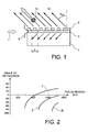
- a waveguide 2 is formed on a substrate 4.
- a diffraction grating 6 is located or deposited or formed on this guide 2.
- Radiation 7 (including a is designated by reference 8) is injected into the guide 2, for example using a coupling by the slice, by means to inject into the guide a radiation at the desired wavelength.
- such means comprise a prism or a other network.
- the network 6 makes it possible to decouple the light from the guided mode to the outside.
- the diffracted light In the middle 14, the diffracted light generates an "optical force" that allows acting on, for example, a particle 10 located near the network.
- a network is preferably used whose step is between the two limits given by formulas (3) and (4), so as not to diffraction only for a single order, and therefore a propulsion of particles in one direction.
- FIG. 2 represents the diffraction angles of the different orders (order -1: curve I, order -2: curve II; order -3: curve III) of a network in function of the pitch of this network.
- the superstrate 14 considered has an index of 1.33 (identical to that of water) and the waveguide 2, under the network, a effective index of 1.6.
- the working wavelength is 1064 nm.
- a further increase in the pace causes a reversal of the diffraction direction (positive angles) and a reversal of the direction of the particle.
- We then reach the limit of diffraction of order -2 for ⁇ 726nm.
- the particle 10 placed above the network 6 will be hit by the diffracted wave that goes the push in the chosen direction.
- cross sections depend on directly from the optical index of the particle but also of its volume.
- two particles of different materials or of different sizes will have different speeds of movement, which allows for example to perform a sort of these particles. For example, a 1 ⁇ m gold ball diameter will move faster than a latex ball same size.
- the device thus described presents the property of being able to move, without contact and with high speeds (several microns per second, or more) particles (or biological objects) of micrometric or nanometric size, this size being for example between 10 microns and 50 nm. Of more, it allows to sort natures particles or of different sizes.
- n sub represents the index of the substrate 4
- an intensity will actually be diffracted in the latter if: eff + not sub > ⁇ ⁇
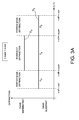
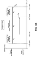
- Figures 3A and 3B identify the different possible cases depending on the values relative indices of substrate 4 and superstrate 14.
- Figure 3A corresponds to the case where nsuper ⁇ nsub and Figure 3B in case nsuper> nsub.
- the lines D2 and D4 correspond to the case nsuper> nsub, and the lines D1 and D3 to the case nsuper ⁇ nsub.
- zones A1 and A'1 of the FIG. 3B (nsuper> nsub and neff - nsuper ⁇ / ⁇ ⁇ neff - nsub (A1) or neff + nsub ⁇ / ⁇ ⁇ neff + nsuper (A'1)), there is diffraction in the superstrate and no loss in the substrate. Losses appear in the substrate for zone A2, for which there is always diffraction in the superstrate, ie when neff + nsub> ⁇ / ⁇ > neff - nsub.
- This layer intermediate could be for example a layer of silica deposited by a sol-gel technology that presents an index of about 1.22.
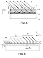
- Figure 5 Another embodiment is shown in Figure 5. It consists of placing a mirror of Bragg 20 in the substrate 4.
- This mirror refers to the outside environment 14 diffracted light in the substrate 4.
- the multilayer deposit 20 comprises a alternating dielectric thin films that do not absorb light at the wavelength of the 7. These successively present a subscript high refraction, noted nh (possible materials: TiO2, HfO2, Si3N4, Ta2O5, Al2O3, In2O3) and an index bottom rated nb (possible materials: SiO2, MgF2, LiF).
- PVD Physical Vapor Deposition
- CVD chemical Vapor Deposition
- the wave reflected by the mirror will, after reflection on this mirror, then after having crossed the network, the same direction as that resulting from the network 6 to the superstrate.
- the direction of particle 10 is related to no network.
- Variations in the pace of the network and its lateral dimensions will for example be realized thanks to an appropriate mask. Height variations of reasons will be made either by the use of several levels of masking either by the use of layers with thickness gradients associated with a selective engraving.
- the network implemented may comprise a plurality of patterns, each pattern being different from other reasons, for example by at least his step and / or a width w1 or w2 and / or its height h.
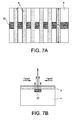
- the particles are confined to a track using, under network 6, a waveguide 22 of limited width (Fig. 7A which represents a view top of the device).
- Fig. 7A which represents a view top of the device.
- FIG. 8A Schematic view from above
- FIG. 8B This embodiment is represented on Figures 8A (schematic view from above) and 8B. he allows to generate a "lateral" diffraction of radiation, which will meet the particle and the guide along a "focal line". We will control so the position of the particle in the three dimensions of space, which makes it possible to envisage more complex trajectories (for example a nonlinear or serpentine trajectory or a curved path in a plane parallel to the substrate).
- the realization of this type of device is similar to that of the basic device but uses a mask on which prints curves instead of lines traditional network.
- the guide wave can be realized by an exchange method of traditional ions with silver ions on a BK7 substrate.
- the thickness of the guide will be chosen from way to work with a single mode guide for the desired wavelength. We can also use everything dielectric material allowing effective guiding of light or still work on a substrate of silicon.
- the network may be made of resin, titanium oxide (TiO2) or nitride. he can be engraved by a lithography technology by electron beam or by a technology of precision lithography.
- Another example of embodiment concerns a structure with a Bragg mirror, as on the figure 5.
- the substrate 4 is for example silicon.
- a Bragg mirror 20 which avoids light leakage in the substrate.
- a Bragg mirror 20 which avoids light leakage in the substrate.
- the substrate for a wavelength of work of 1064 nm, we can cover the substrate a multilayer 20 constituted by the alternation of thin layers of 264 nm thick silica and thin layers of titanium dioxide 123 nm thick deposited in IBS.
- the multilayer will consist of 20 thin layers then covered by a layer Silica insulation 2 ⁇ m thick.
- the mirror thus realized allows to reflect all the rays arriving in an angular range of between 35 ° and 70 °.
- the waveguide 2 may, for example, be made of nitride (Si3N4) by deposition techniques (LPCVD for example). We will be able to choose a thickness of 223 nm of nitride and a width of 1 ⁇ m guide.
- the network 6 will be made of resin, titanium oxide (TiO2) or nitride thanks to several overlapping masking levels that allow a spatial variation of the thickness of the network.
Landscapes
- Physics & Mathematics (AREA)
- Spectroscopy & Molecular Physics (AREA)
- Engineering & Computer Science (AREA)
- General Engineering & Computer Science (AREA)
- High Energy & Nuclear Physics (AREA)
- Diffracting Gratings Or Hologram Optical Elements (AREA)
- Optical Integrated Circuits (AREA)
- Control And Other Processes For Unpacking Of Materials (AREA)
- Physical Or Chemical Processes And Apparatus (AREA)
- Glanulating (AREA)
- Developing Agents For Electrophotography (AREA)
- Combined Means For Separation Of Solids (AREA)
Applications Claiming Priority (2)
| Application Number | Priority Date | Filing Date | Title |
|---|---|---|---|
| FR0350679A FR2860886B1 (fr) | 2003-10-14 | 2003-10-14 | Dispositif de deplacement de particules |
| FR0350679 | 2003-10-14 |
Publications (2)
| Publication Number | Publication Date |
|---|---|
| EP1524675A1 true EP1524675A1 (de) | 2005-04-20 |
| EP1524675B1 EP1524675B1 (de) | 2011-04-06 |
Family
ID=34355522
Family Applications (1)
| Application Number | Title | Priority Date | Filing Date |
|---|---|---|---|
| EP04104982A Expired - Lifetime EP1524675B1 (de) | 2003-10-14 | 2004-10-12 | Vorrichtung und Verfahren zur Verschiebung von Teilchen |
Country Status (6)
| Country | Link |
|---|---|
| US (2) | US7211787B2 (de) |
| EP (1) | EP1524675B1 (de) |
| JP (1) | JP2005161514A (de) |
| AT (1) | ATE504925T1 (de) |
| DE (1) | DE602004032097D1 (de) |
| FR (1) | FR2860886B1 (de) |
Families Citing this family (6)
| Publication number | Priority date | Publication date | Assignee | Title |
|---|---|---|---|---|
| FR2863182B1 (fr) * | 2003-12-04 | 2006-10-13 | Commissariat Energie Atomique | Procede de concentration de particules. |
| JP5284036B2 (ja) * | 2007-11-14 | 2013-09-11 | キヤノン株式会社 | 発光装置 |
| JP2011065546A (ja) * | 2009-09-18 | 2011-03-31 | Hitachi Solutions Ltd | ファイル検索システム及びプログラム |
| KR101817638B1 (ko) | 2016-08-31 | 2018-01-11 | 국방과학연구소 | 유전체다층박막 회절격자 |
| RU2666416C1 (ru) * | 2017-07-14 | 2018-09-07 | федеральное государственное автономное образовательное учреждение высшего образования "Тюменский государственный университет" | Способ очистки твердой поверхности от микрочастиц |
| DE112022001270T5 (de) | 2021-06-25 | 2024-01-04 | Ams-Osram Ag | Schwebstoffdetektor und verfahren zum nachweis von schwebstoffen |
Citations (3)
| Publication number | Priority date | Publication date | Assignee | Title |
|---|---|---|---|---|
| WO2000069554A1 (en) * | 1999-05-17 | 2000-11-23 | Marchitto Kevin S | Electromagnetic energy driven separation methods |
| US20030111594A1 (en) * | 2001-12-13 | 2003-06-19 | Commissariat A L'energie Atomique | Optical device and optical process for particle displacement |
| WO2003065774A1 (en) * | 2002-01-29 | 2003-08-07 | Forskningscenter Risø | Multi-beam optical tweezers |
Family Cites Families (15)
| Publication number | Priority date | Publication date | Assignee | Title |
|---|---|---|---|---|
| US3778612A (en) * | 1969-12-15 | 1973-12-11 | A Ashkin | Neutral particle beam separator and velocity analyzer using radiation pressure |
| GB2256477B (en) * | 1991-06-07 | 1995-03-08 | Marconi Gec Ltd | An optical sensor |
| US6797942B2 (en) * | 2001-09-13 | 2004-09-28 | University Of Chicago | Apparatus and process for the lateral deflection and separation of flowing particles by a static array of optical tweezers |
| US6055106A (en) * | 1998-02-03 | 2000-04-25 | Arch Development Corporation | Apparatus for applying optical gradient forces |
| US6956230B1 (en) * | 1999-09-17 | 2005-10-18 | California Institute Of Technology | Integrated particles sensor formed on single substrate using fringes formed by diffractive elements |
| US6744038B2 (en) * | 2000-11-13 | 2004-06-01 | Genoptix, Inc. | Methods of separating particles using an optical gradient |
| US6833542B2 (en) * | 2000-11-13 | 2004-12-21 | Genoptix, Inc. | Method for sorting particles |
| AU3053002A (en) * | 2000-11-28 | 2002-06-11 | Univ California | Optical switching and sorting of biological samples and microparticles transported in a micro-fluidic device, including integrated bio-chip devices |
| US6778724B2 (en) * | 2000-11-28 | 2004-08-17 | The Regents Of The University Of California | Optical switching and sorting of biological samples and microparticles transported in a micro-fluidic device, including integrated bio-chip devices |
| EP1373875A2 (de) * | 2001-04-02 | 2004-01-02 | Zeptosens AG | Optische struktur zur multi-photonen-anregung und deren verwendung |
| JP3883930B2 (ja) * | 2001-12-10 | 2007-02-21 | 日本電信電話株式会社 | ホログラム媒体 |
| US7109473B2 (en) * | 2002-09-16 | 2006-09-19 | University Of Chicago | Transverse optical accelerator and generalized optical vortices |
| US20040067167A1 (en) * | 2002-10-08 | 2004-04-08 | Genoptix, Inc. | Methods and apparatus for optophoretic diagnosis of cells and particles |
| US7038874B1 (en) | 2003-05-19 | 2006-05-02 | International Business Machines Corporation | Tamper resistant write once recording of a data storage cartridge having rewritable media |
| US20050070027A1 (en) * | 2003-09-30 | 2005-03-31 | Jacques Gollier | Double resonance interrogation of grating-coupled waveguides |
-
2003
- 2003-10-14 FR FR0350679A patent/FR2860886B1/fr not_active Expired - Fee Related
-
2004
- 2004-10-12 EP EP04104982A patent/EP1524675B1/de not_active Expired - Lifetime
- 2004-10-12 AT AT04104982T patent/ATE504925T1/de not_active IP Right Cessation
- 2004-10-12 DE DE602004032097T patent/DE602004032097D1/de not_active Expired - Lifetime
- 2004-10-13 US US10/962,603 patent/US7211787B2/en not_active Expired - Fee Related
- 2004-10-13 JP JP2004299273A patent/JP2005161514A/ja active Pending
-
2007
- 2007-02-05 US US11/671,050 patent/US7633056B2/en not_active Expired - Fee Related
Patent Citations (3)
| Publication number | Priority date | Publication date | Assignee | Title |
|---|---|---|---|---|
| WO2000069554A1 (en) * | 1999-05-17 | 2000-11-23 | Marchitto Kevin S | Electromagnetic energy driven separation methods |
| US20030111594A1 (en) * | 2001-12-13 | 2003-06-19 | Commissariat A L'energie Atomique | Optical device and optical process for particle displacement |
| WO2003065774A1 (en) * | 2002-01-29 | 2003-08-07 | Forskningscenter Risø | Multi-beam optical tweezers |
Non-Patent Citations (2)
| Title |
|---|
| OGURA Y ET AL: "OPTICAL LEVITATION AND TRANSLATION OF A MICROSCOPIC PARTICLE BY USE OF MULTIPLE BEAMS GENERATED BY VERTICAL-CAVITY SURFACE-EMITTING LASER ARRAY SOURCES", APPLIED OPTICS, OPTICAL SOCIETY OF AMERICA,WASHINGTON, US, vol. 41, no. 27, 20 September 2002 (2002-09-20), pages 5645 - 5654, XP001130498, ISSN: 0003-6935 * |
| ROSENBLATT D ET AL: "RESONANT GRATING WAVEGUIDE STRUCTURES", IEEE JOURNAL OF QUANTUM ELECTRONICS, IEEE INC. NEW YORK, US, vol. 33, no. 11, 1 November 1997 (1997-11-01), pages 2038 - 2059, XP000725006, ISSN: 0018-9197 * |
Also Published As
| Publication number | Publication date |
|---|---|
| US7211787B2 (en) | 2007-05-01 |
| US20050184230A1 (en) | 2005-08-25 |
| FR2860886B1 (fr) | 2005-12-23 |
| US20070145256A1 (en) | 2007-06-28 |
| ATE504925T1 (de) | 2011-04-15 |
| FR2860886A1 (fr) | 2005-04-15 |
| JP2005161514A (ja) | 2005-06-23 |
| EP1524675B1 (de) | 2011-04-06 |
| US7633056B2 (en) | 2009-12-15 |
| DE602004032097D1 (de) | 2011-05-19 |
Similar Documents
| Publication | Publication Date | Title |
|---|---|---|
| EP0461991B1 (de) | Integriertes optisches Monomode-Raumfilter und Verfahren zu seiner Herstellung | |
| EP0451047B1 (de) | Vor Umwelteinflüssen geschützte integrierte optische Komponente und Verfahren zu ihrer Herstellung | |
| EP3460547A1 (de) | Optische kopplungsvorrichtung für einen photonenschaltkreis | |
| EP0367675B1 (de) | Integrierte Optikvorrichtung zur Messung des Brechungsindex einer Flüssigkeit | |
| FR2459986A1 (fr) | Lentille de fresnel integree | |
| EP0143031A2 (de) | Optisches Umschaltgerät mit elektrischer Steuerung | |
| EP0584005B1 (de) | Integrierter optischer Sensor, insbesondere für chemische Substanzen | |
| FR2613826A1 (fr) | Capteur de deplacement en optique integree | |
| EP1524675B1 (de) | Vorrichtung und Verfahren zur Verschiebung von Teilchen | |
| FR2498340A1 (fr) | Procede et appareil de detection d'un signal d'erreur de focalisation d'un objectif | |
| EP0138668B1 (de) | Einrichtung zur Aufnahme eines kohärenten Bildes in einem multimoden-optischen Hohlraum | |
| WO1993014378A1 (fr) | Gyrometre optique a effet sagnac en structure completement integree | |
| EP4052073A1 (de) | Diffraktives optisches element mit einer metaoberfläche für die tirf-mikroskopie | |
| FR2835064A1 (fr) | Element optique a cristal photonique | |
| EP3513230B1 (de) | Optische kupplungsvorrichtung | |
| FR2837002A1 (fr) | Element optique utilisant un cristal photonique bidimensionnel et demultiplexeur associe | |
| FR2970079A1 (fr) | Dispositif de type biopuce | |
| EP0585333B1 (de) | Optisch integrierte, interferometrische messvorrichtung | |
| FR3052923A1 (fr) | Reflecteur optique resonant a multiples couches minces de materiaux dielectriques, capteur optique et dispositif d'amplification laser comportant un tel reflecteur | |
| EP2145331B1 (de) | Verfahren und system zum lesen optischer informationen mit hoher dichte | |
| EP3601678B1 (de) | Vorrichtung zur wellenenergiesteuerung | |
| EP3314319B1 (de) | Optischer leiter | |
| FR2940450A1 (fr) | Dispositif et procede pour etudier une zone d'etude par onde acoustique | |
| Yu | Theoretical analysis, design and fabrication of nano-opto-mechanical systems (NOMS) | |
| EP1397712A1 (de) | Übertragungselement für lichtwellen zwischen optischen komponenten und zugehöriges herstellungsverfahren |
Legal Events
| Date | Code | Title | Description |
|---|---|---|---|
| PUAI | Public reference made under article 153(3) epc to a published international application that has entered the european phase |
Free format text: ORIGINAL CODE: 0009012 |
|
| AK | Designated contracting states |
Kind code of ref document: A1 Designated state(s): AT BE BG CH CY CZ DE DK EE ES FI FR GB GR HU IE IT LI LU MC NL PL PT RO SE SI SK TR |
|
| AX | Request for extension of the european patent |
Extension state: AL HR LT LV MK |
|
| RIN1 | Information on inventor provided before grant (corrected) |
Inventor name: HAZART, JEROEME Inventor name: GAUGIRAN, STEPHANIE |
|
| 17P | Request for examination filed |
Effective date: 20051010 |
|
| AKX | Designation fees paid |
Designated state(s): AT BE BG CH CY CZ DE DK EE ES FI FR GB GR HU IE IT LI LU MC NL PL PT RO SE SI SK TR |
|
| RAP1 | Party data changed (applicant data changed or rights of an application transferred) |
Owner name: COMMISSARIAT A L'ENERGIE ATOMIQUE |
|
| 17Q | First examination report despatched |
Effective date: 20081114 |
|
| RAP1 | Party data changed (applicant data changed or rights of an application transferred) |
Owner name: COMMISSARIAT A L'ENERGIE ATOMIQUE ET AUX ENERGIES |
|
| GRAP | Despatch of communication of intention to grant a patent |
Free format text: ORIGINAL CODE: EPIDOSNIGR1 |
|
| RTI1 | Title (correction) |
Free format text: APPARATUS AND METHOD FOR DISPLACEMENT OF PARTICLES |
|
| GRAS | Grant fee paid |
Free format text: ORIGINAL CODE: EPIDOSNIGR3 |
|
| GRAA | (expected) grant |
Free format text: ORIGINAL CODE: 0009210 |
|
| AK | Designated contracting states |
Kind code of ref document: B1 Designated state(s): AT BE BG CH CY CZ DE DK EE ES FI FR GB GR HU IE IT LI LU MC NL PL PT RO SE SI SK TR |
|
| REG | Reference to a national code |
Ref country code: GB Ref legal event code: FG4D Free format text: NOT ENGLISH |
|
| REG | Reference to a national code |
Ref country code: CH Ref legal event code: EP |
|
| REG | Reference to a national code |
Ref country code: IE Ref legal event code: FG4D |
|
| REF | Corresponds to: |
Ref document number: 602004032097 Country of ref document: DE Date of ref document: 20110519 Kind code of ref document: P |
|
| REG | Reference to a national code |
Ref country code: DE Ref legal event code: R096 Ref document number: 602004032097 Country of ref document: DE Effective date: 20110519 |
|
| REG | Reference to a national code |
Ref country code: NL Ref legal event code: VDEP Effective date: 20110406 |
|
| PG25 | Lapsed in a contracting state [announced via postgrant information from national office to epo] |
Ref country code: SI Free format text: LAPSE BECAUSE OF FAILURE TO SUBMIT A TRANSLATION OF THE DESCRIPTION OR TO PAY THE FEE WITHIN THE PRESCRIBED TIME-LIMIT Effective date: 20110406 |
|
| REG | Reference to a national code |
Ref country code: IE Ref legal event code: FD4D |
|
| PG25 | Lapsed in a contracting state [announced via postgrant information from national office to epo] |
Ref country code: SE Free format text: LAPSE BECAUSE OF FAILURE TO SUBMIT A TRANSLATION OF THE DESCRIPTION OR TO PAY THE FEE WITHIN THE PRESCRIBED TIME-LIMIT Effective date: 20110406 Ref country code: PT Free format text: LAPSE BECAUSE OF FAILURE TO SUBMIT A TRANSLATION OF THE DESCRIPTION OR TO PAY THE FEE WITHIN THE PRESCRIBED TIME-LIMIT Effective date: 20110808 |
|
| PG25 | Lapsed in a contracting state [announced via postgrant information from national office to epo] |
Ref country code: AT Free format text: LAPSE BECAUSE OF FAILURE TO SUBMIT A TRANSLATION OF THE DESCRIPTION OR TO PAY THE FEE WITHIN THE PRESCRIBED TIME-LIMIT Effective date: 20110406 Ref country code: CY Free format text: LAPSE BECAUSE OF FAILURE TO SUBMIT A TRANSLATION OF THE DESCRIPTION OR TO PAY THE FEE WITHIN THE PRESCRIBED TIME-LIMIT Effective date: 20110406 Ref country code: ES Free format text: LAPSE BECAUSE OF FAILURE TO SUBMIT A TRANSLATION OF THE DESCRIPTION OR TO PAY THE FEE WITHIN THE PRESCRIBED TIME-LIMIT Effective date: 20110717 Ref country code: FI Free format text: LAPSE BECAUSE OF FAILURE TO SUBMIT A TRANSLATION OF THE DESCRIPTION OR TO PAY THE FEE WITHIN THE PRESCRIBED TIME-LIMIT Effective date: 20110406 Ref country code: GR Free format text: LAPSE BECAUSE OF FAILURE TO SUBMIT A TRANSLATION OF THE DESCRIPTION OR TO PAY THE FEE WITHIN THE PRESCRIBED TIME-LIMIT Effective date: 20110707 |
|
| PG25 | Lapsed in a contracting state [announced via postgrant information from national office to epo] |
Ref country code: NL Free format text: LAPSE BECAUSE OF FAILURE TO SUBMIT A TRANSLATION OF THE DESCRIPTION OR TO PAY THE FEE WITHIN THE PRESCRIBED TIME-LIMIT Effective date: 20110406 |
|
| PG25 | Lapsed in a contracting state [announced via postgrant information from national office to epo] |
Ref country code: EE Free format text: LAPSE BECAUSE OF FAILURE TO SUBMIT A TRANSLATION OF THE DESCRIPTION OR TO PAY THE FEE WITHIN THE PRESCRIBED TIME-LIMIT Effective date: 20110406 Ref country code: CZ Free format text: LAPSE BECAUSE OF FAILURE TO SUBMIT A TRANSLATION OF THE DESCRIPTION OR TO PAY THE FEE WITHIN THE PRESCRIBED TIME-LIMIT Effective date: 20110406 Ref country code: IE Free format text: LAPSE BECAUSE OF FAILURE TO SUBMIT A TRANSLATION OF THE DESCRIPTION OR TO PAY THE FEE WITHIN THE PRESCRIBED TIME-LIMIT Effective date: 20110406 |
|
| PLBE | No opposition filed within time limit |
Free format text: ORIGINAL CODE: 0009261 |
|
| STAA | Information on the status of an ep patent application or granted ep patent |
Free format text: STATUS: NO OPPOSITION FILED WITHIN TIME LIMIT |
|
| PG25 | Lapsed in a contracting state [announced via postgrant information from national office to epo] |
Ref country code: RO Free format text: LAPSE BECAUSE OF FAILURE TO SUBMIT A TRANSLATION OF THE DESCRIPTION OR TO PAY THE FEE WITHIN THE PRESCRIBED TIME-LIMIT Effective date: 20110406 Ref country code: DK Free format text: LAPSE BECAUSE OF FAILURE TO SUBMIT A TRANSLATION OF THE DESCRIPTION OR TO PAY THE FEE WITHIN THE PRESCRIBED TIME-LIMIT Effective date: 20110406 Ref country code: PL Free format text: LAPSE BECAUSE OF FAILURE TO SUBMIT A TRANSLATION OF THE DESCRIPTION OR TO PAY THE FEE WITHIN THE PRESCRIBED TIME-LIMIT Effective date: 20110406 Ref country code: SK Free format text: LAPSE BECAUSE OF FAILURE TO SUBMIT A TRANSLATION OF THE DESCRIPTION OR TO PAY THE FEE WITHIN THE PRESCRIBED TIME-LIMIT Effective date: 20110406 |
|
| 26N | No opposition filed |
Effective date: 20120110 |
|
| BERE | Be: lapsed |
Owner name: COMMISSARIAT A L'ENERGIE ATOMIQUE ET AUX ENERGIES Effective date: 20111031 |
|
| REG | Reference to a national code |
Ref country code: DE Ref legal event code: R097 Ref document number: 602004032097 Country of ref document: DE Effective date: 20120110 |
|
| PG25 | Lapsed in a contracting state [announced via postgrant information from national office to epo] |
Ref country code: MC Free format text: LAPSE BECAUSE OF NON-PAYMENT OF DUE FEES Effective date: 20111031 |
|
| REG | Reference to a national code |
Ref country code: CH Ref legal event code: PL |
|
| GBPC | Gb: european patent ceased through non-payment of renewal fee |
Effective date: 20111012 |
|
| REG | Reference to a national code |
Ref country code: FR Ref legal event code: ST Effective date: 20120629 |
|
| PG25 | Lapsed in a contracting state [announced via postgrant information from national office to epo] |
Ref country code: LI Free format text: LAPSE BECAUSE OF NON-PAYMENT OF DUE FEES Effective date: 20111031 Ref country code: BE Free format text: LAPSE BECAUSE OF NON-PAYMENT OF DUE FEES Effective date: 20111031 Ref country code: DE Free format text: LAPSE BECAUSE OF NON-PAYMENT OF DUE FEES Effective date: 20120501 Ref country code: CH Free format text: LAPSE BECAUSE OF NON-PAYMENT OF DUE FEES Effective date: 20111031 |
|
| REG | Reference to a national code |
Ref country code: DE Ref legal event code: R119 Ref document number: 602004032097 Country of ref document: DE Effective date: 20120501 |
|
| PG25 | Lapsed in a contracting state [announced via postgrant information from national office to epo] |
Ref country code: FR Free format text: LAPSE BECAUSE OF NON-PAYMENT OF DUE FEES Effective date: 20111102 Ref country code: GB Free format text: LAPSE BECAUSE OF NON-PAYMENT OF DUE FEES Effective date: 20111012 |
|
| PG25 | Lapsed in a contracting state [announced via postgrant information from national office to epo] |
Ref country code: LU Free format text: LAPSE BECAUSE OF NON-PAYMENT OF DUE FEES Effective date: 20111012 |
|
| PG25 | Lapsed in a contracting state [announced via postgrant information from national office to epo] |
Ref country code: BG Free format text: LAPSE BECAUSE OF FAILURE TO SUBMIT A TRANSLATION OF THE DESCRIPTION OR TO PAY THE FEE WITHIN THE PRESCRIBED TIME-LIMIT Effective date: 20110706 |
|
| PG25 | Lapsed in a contracting state [announced via postgrant information from national office to epo] |
Ref country code: TR Free format text: LAPSE BECAUSE OF FAILURE TO SUBMIT A TRANSLATION OF THE DESCRIPTION OR TO PAY THE FEE WITHIN THE PRESCRIBED TIME-LIMIT Effective date: 20110406 |
|
| PG25 | Lapsed in a contracting state [announced via postgrant information from national office to epo] |
Ref country code: HU Free format text: LAPSE BECAUSE OF FAILURE TO SUBMIT A TRANSLATION OF THE DESCRIPTION OR TO PAY THE FEE WITHIN THE PRESCRIBED TIME-LIMIT Effective date: 20110406 |
|
| PG25 | Lapsed in a contracting state [announced via postgrant information from national office to epo] |
Ref country code: IT Free format text: LAPSE BECAUSE OF FAILURE TO SUBMIT A TRANSLATION OF THE DESCRIPTION OR TO PAY THE FEE WITHIN THE PRESCRIBED TIME-LIMIT Effective date: 20110406 |