EP1524728B1 - Elektrischer Verbinder - Google Patents
Elektrischer Verbinder Download PDFInfo
- Publication number
- EP1524728B1 EP1524728B1 EP04104977A EP04104977A EP1524728B1 EP 1524728 B1 EP1524728 B1 EP 1524728B1 EP 04104977 A EP04104977 A EP 04104977A EP 04104977 A EP04104977 A EP 04104977A EP 1524728 B1 EP1524728 B1 EP 1524728B1
- Authority
- EP
- European Patent Office
- Prior art keywords
- retainer
- housing
- main locking
- locking position
- contacts
- Prior art date
- Legal status (The legal status is an assumption and is not a legal conclusion. Google has not performed a legal analysis and makes no representation as to the accuracy of the status listed.)
- Expired - Lifetime
Links
- 238000007689 inspection Methods 0.000 claims description 13
- 239000000523 sample Substances 0.000 claims description 13
- 230000008093 supporting effect Effects 0.000 claims description 13
- 238000003780 insertion Methods 0.000 claims description 11
- 230000037431 insertion Effects 0.000 claims description 11
- 230000001105 regulatory effect Effects 0.000 description 34
- 239000011797 cavity material Substances 0.000 description 29
- 230000013011 mating Effects 0.000 description 13
- 238000001514 detection method Methods 0.000 description 10
- 238000012790 confirmation Methods 0.000 description 5
- 230000000007 visual effect Effects 0.000 description 5
- 238000011179 visual inspection Methods 0.000 description 4
- 238000000034 method Methods 0.000 description 3
- 238000000465 moulding Methods 0.000 description 2
- 229920003002 synthetic resin Polymers 0.000 description 2
- 239000000057 synthetic resin Substances 0.000 description 2
- 238000010276 construction Methods 0.000 description 1
- 238000002788 crimping Methods 0.000 description 1
- 238000010586 diagram Methods 0.000 description 1
- 230000000694 effects Effects 0.000 description 1
- 150000002500 ions Chemical class 0.000 description 1
- 238000005259 measurement Methods 0.000 description 1
- 239000002184 metal Substances 0.000 description 1
- 229940069435 retaine Drugs 0.000 description 1
- 230000000717 retained effect Effects 0.000 description 1
Images


Classifications
-
- H—ELECTRICITY
- H01—ELECTRIC ELEMENTS
- H01R—ELECTRICALLY-CONDUCTIVE CONNECTIONS; STRUCTURAL ASSOCIATIONS OF A PLURALITY OF MUTUALLY-INSULATED ELECTRICAL CONNECTING ELEMENTS; COUPLING DEVICES; CURRENT COLLECTORS
- H01R13/00—Details of coupling devices of the kinds covered by groups H01R12/70 or H01R24/00 - H01R33/00
- H01R13/40—Securing contact members in or to a base or case; Insulating of contact members
- H01R13/42—Securing in a demountable manner
- H01R13/436—Securing a plurality of contact members by one locking piece or operation
- H01R13/4364—Insertion of locking piece from the front
- H01R13/4365—Insertion of locking piece from the front comprising a temporary and a final locking position
Definitions
- the present invention relates to an electrical connector comprising a retainer which is inserted from the front surface of the housing, and which is locked to the housing in a temporary locking position that allows the insertion o f contacts into the housing and in a main locking position that ensures that the contacts are prevented from slipping out of the housing.
- the electrical connector shown in Fig s. 19A and 19B has been known as an electrical connector comprising a retainer that is inserted from the front surface of the housing, i.e., a so-called front insertion type retainer.
- the electrical connector 101 shown in these Fig s. 19A and 19B comprises an insulating housing 110, contacts 120 that are accommodated in this housing 110, and a retainer 130 that is inserted from the front surface of the housing 110 and that ensures that the contacts 120 are prevented from slipping out of the housin g 110.
- a plurality of contact accommodating cavities 111 for accommodating the contacts 120 are formed inside the housing 110.
- a housing lance 112 for accommodating the corresponding contact 120 is disposed inside each contact accommodating cavity 111.
- a space 113 that allows the flexing of the housing lance 112 is formed beneath each housing lance 112 (below in Fig. 19A ).
- the retainer 130 is constructed so that this retainer is inserted into the housing 110 from the front surface (left s urface in Fig. 19A ) of the housing 110, and comprises a plurality of regulating parts 131 that advance into the spaces 113 formed beneath the housing lances 112 and restrict the downward movement of the housing lances 112, thus ensuring that the contacts 120 do not slip out.
- a pair of locking parts 132 that advance into locking holes 114 formed in both side walls of the housing 110 and thus prevent the retainer 130 from slipping out with respect to the housing 110 are formed to protrude from both side wall s of the retainer 130 in locking positions that ensure that the contacts 120 will not slip out.
- the electrical connector shown in Fig. 20 is known as an electrical connector with a construction which is such that the locked state of the electrical connector and the mating connector can be confirmed by visual inspection.
- the electrical connector 201 shown in Fig. 20 comprises a housing 210 that accommodates a plurality of female contacts (not shown in the figure), a supporting part that protrudes upward from the housing 210, and a pair of arm parts 212 that respectively extend in the forward-rearward direction from the left and right side edges of the supporting part . Furthermore, locking projecting parts 213 are formed so that these parts 213 protrude from the front ends (upper ends in Fig. 20 ) of the respective arm parts 212, and operating parts 214 are formed on the rear ends of the respective arm parts 212. Furthermore, detection projecting parts 215 are formed so that these parts 215 protrude to the outside on the front ends of the operating parts 214 of the respective arm parts 212.
- the mating connector 301 that mates with the electrical connector 201 comprises a housing 310 to which a p1 urality of male contacts 311 are fastened, and a hood part 312 that surrounds the housing 310 and that extends forward (downward in Fig. 20 ).
- a pair of locking parts 313 to which the locking projecting parts 213 are secured at the time of mating with the electrical connector 201 are formed on the hood part 312.
- window holes 314 into which the detection projecting parts 215 advance when the locking projecting parts 213 are locked to the locking parts 313 are formed in the left and right side w alls of the hood part 312.
- the lock ed state of the electrical connector 201 with the mating connector 301 can be visually confirmed by visually inspecting the detection projecting parts 215 from the outside of the hood part 312.
- the main body of the retainer 130 possesses rigidity against the locking parts 132 that are disposed on both side walls of this m ain body. Accordingly, when the retainer 130 is inserted from the front surface of the housing 110 and moved to the locking position, there is a danger that the locking parts 132 will be crushed by the side walls of the housing 110, or that the side walls of the housing 110 will be deformed.
- each of the pair of arm parts 212 possesses flexibility, and has a structure that allows swinging inward and outward about the left and right side edges of the supporting part. Accordingly, each of the arm parts 212 can flex inward even in a state in which the detection protruding parts 215 have advanced into the window holes 314.
- each of the arm parts 212 flexes inward as a result of the pressing of the inspection probe, so that the detection protruding parts 215 are retracted to the inside, thus making measurement impossible. Accordingly, the locked state with the mating connector 301 cannot be accurately detected using an inspection probe.
- EP-A-1168516 describes a waterproof electrical connector comprising inner and outer housings.
- a provisional retaining member and a complete retaining member formed on the inner housing are engagable with an engagement portion of the outer housing to hold the two housings in a provisionally-fitted condition and a completely-fitted condition.
- each terminal which is inserted into a tubular insertion path of the outer housing is received in a chamber of the inner housing, is retained by a flexible retainer, and a front portion of the inner housing forwardly projects a predetermined distance from the front side of the outer housing.
- a visual confirmation member provided at a rear portion of the terminal, is moved in the insertion path, and the movement of the visual confirmation member can be visually confirmed from the rear side of the outer housing.
- US-A-5931700 discloses a female connector comprising a housing body and a hood projecting from the front of the body.
- a plurality of terminal accommodating cavities are provided in two tiers in the housing body and each of the terminal cavities has a front end stopper and a cantilevered resilient locking piece for locking an associated terminal in the cavity.
- a terminal insertion detecting member is inserted into the hood and is coupled to the connector in a provisional locking position in which a provisional locking projection on a resilient locking arm of the detecting member engages a locking portion formed at an open rear end of a locking frame portion of the connector.
- terminals are insertable into the terminal cavities from the rear of the housing body and, subject to these being correctly inserted, the detecting member can be moved to a full locking position in which full locking projections engage the locking portion of the connector. In the full locking position, the locking projections are exposed at the top of the housing body.
- the present invention was devised in the light of the problems described above. It is an object of the present invention to provide an electrical connector equipped with a retainer that can be inserted from the front surface of the housing, and that can be secured in the housing in a temporary locking position that allows the insertion of contacts into the housing and in a main locking position that ensures that the contacts will not slip out, wherein the state of the retainer in the main locking position can easily be confirmed by visual inspection or by an inspection probe.
- the electrical connector of Claim 1 that is in an electrical connector equipped with a retainer lockable to the housing in a temporary locking position and in a main locking position, since the main locking projections are exposed via side surfaces of the housing, when the retainer is in the main locking position, and since the housing has supporting parts that support the back surface sides of the main locking arms in the vicinity of the main locking projections when the retainer is in the main locking position, the state of the retainer in the main locking position can easily be confirmed by visually inspecting the main locking projections, formed on the retainer, from the side surfaces of the housing, or by measuring the height of the main locking projections using an inspection probe.
- the flexing permitting spaces allowing flexing of the main locking arms of the retainer and formed in positions located further forward than the supporting parts of the housing enable movement of the retainer from the temporary locking position to the main locking position to be easily accomplished while maintaining the
- the plug connector 1 comprises an insulating housing 10, a plurality of contacts 20 that are accommodated in this housing 10 in two rows (upper and lower rows), and a retainer 30 for ensuring that the contacts 20 do not slip out.
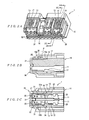
- the housing 10 is formed with a substantially rectangular shape by molding an ins ulating synthetic resin, and has a plurality of contact accommodating cavities 11 (that accommodate contacts 20 inside) in two rows (upper and lower rows) in the left -right direction (in the left-right direction in Fig. 1A ). As is shown in Fig. 3 , each co ntact accommodating cavity 11 opens on the front side of the housing 10 (left side in Figs. 1C and 2C , front side in Fig. 3 ). Furthermore, a housing lance 12 for securing the corresponding contact 20 is disposed in each contact accommodating cavity 11.
- T he housing lances 12 disposed in the contact accommodating cavities 11 of the upper row are formed so that these housing lances extend forward at an inclination from the top wall of the housing 10; on the other hand, the housing lances 12 disposed in the contact accommodating cavities 11 of the lower row are formed so that these housing lances extend forward at an inclination from the bottom wall of the housing 10.
- first long narrow openings 13 that extend in the forward - rearward direction are respectively formed in the top wall and bottom wall of the housing 10 in positions corresponding to the respective contact accommodating cavities 11 in the left -right direction.
- the width of the respective first long narrow openings 13 is narrower than the width of the respective contact accommodating cavities 11.
- spaces 14 that permit flexing of the housing lances 12 and that allow the entry of the upper -side regulating part s 33a (described later) of the retainer 30 are form ed above the housing lances 12 of the upper row so that these spaces 14 communicate with the first long narrow openings 13.
- spaces 14 that permit flexing of the housing lances 12 and that allow the entry of the lower -side regulating parts 33b (described later) of the retainer 30 are also formed beneath the housing lances 12 of the lower row so that these spaces 14 communicate with the first long narrow openings 13.
- the respective spaces 14 open on the front side of the housing 10.
- slits 15 that communicate with the spaces 14 and that open on the front side of the housing 10 are formed on the front side of the housing lances 12 of the respective contact accommodating cavities 11.
- second long narrow openings 17 that extend i n the forward-rearward direction are respectively formed in the top wall of the housing 10 between the first long narrow opening 13 at the leftmost end and the adjacent first long narrow opening 13 and between the first long narrow opening 13 at the rightmost end and the adjacent first long narrow opening 13.
- spaces 18 that allow the entry of the main locking arms 35 (described later) of the retainer 30 are formed beneath the second long narrow openings 17 so that these spaces 18 communicate w ith the second long narrow openings 17.
- the spaces 14 described above and these spaces 18 communicate with each other.
- a locking projection 16 that locks with a cap connector 50 (see Figs. 8A and 8B ) at the time of mating with this cap conne ctor 50 is formed on the top wall of the housing 10.
- each contact 20 is formed by stamping and forming a metal plate, and comprises a substantially box -shaped receptacle part 21 that is secured by the corresponding housing lance 12, and an electrical wire connecting part 22 that extends rearward from the receptacle part 21, and that is connected by crimping to one of the electrical wires of the wire harness (not shown in the figures).
- An elastic contact part 23 that makes elastic contact wit h a mating male contact (not shown in the figures) is disposed inside the receptacle part 21.
- the retainer 30 is inserted from the front surface of the housing 10, and is locked in the housing 10 in a temporary locking position (see Fig s. 1A to 1C) that allows the insertion of the contacts 20 into the housing 10 and in a main locking position (see Fig s. 2A to 2C) that ensures that the contacts 20 do not slip out.
- the retainer 30 comprises a rectangular flat-plate-form board part 31 that exte nds in the direction of length (left -right direction in Fig. 1A ) so as to cover the front surface of the housing 10, and a plurality of upper -side regulating parts 33a and lower-side regulating parts 33b that respectively extend rearward from the upper and lower ends of the board part 31.
- the respective upper-side regulating parts 33a enter into the spaces 14 formed above the housing lances 12 at the time of main locking, and restrict the upward movement of the housing lances 12, thus ensuring that the co ntacts 20 of the upper row do not slip out.
- the respective lower-side regulating parts 33b enter into the spaces 14 formed beneath the housing lances 12 at the time of main locking, and restrict the downward movement of the housing lances 12, thus ensuring that the contacts 20 of the lower row do not slip out.
- a plurality of mating contact passage holes 32 in two rows (upper and lower rows) are formed in the board part 31 in positions corresponding to the respective contact accommodating cavi ties 11. Furthermore, as is shown clearly in Fig. 1C and Figs.
- temporary locking projections 34 that prevent the retainer 30 from being pulled out in the forward direction when the retainer 30 is in the temporary locking position are respecti vely formed on the rear ends of the upper -side regulating parts 33a and lower-side regulating parts 33b that are positioned at both ends in the direction of length.
- the upper-side regulating parts 33a and lower -side regulating parts 33b that are positioned at both ends in the direction of length constitute temporary locking arms.
- a pair of regulating parts 37 that enter the slits 15 of the upper row and restrict the upward movement of the receptacle parts 21 of the contacts 20 of the upper row are formed so that these regulating parts 37 protrude from the respective upper -side regulating parts 33a.
- a pair of regulating parts 37 that enter the slits 15 of the lower row and restrict the downward movement of the receptacle parts 21 of the contacts 20 of the lower row are similarly formed so that these regulating parts 37 protrude from the respective lower -side regulating parts 33b.
- main locking arms 35 are respectively formed between the upper -side regulating part 33a at the leftmost end and the adjacent upper-side regulating part 33a and between the upper-side regulating part 33a at the rightmost end and the adjacent upper -side regulating part 33a.
- the respective main locking arms 35 are formed so that these arms 35 ente r into the spaces 18 formed beneath the second long narrow openings 17 at the time of main locking. As is shown in Fig s.
- main locking projections 36 which are used to prevent the retainer 30 from being pushed in toward the rear when the retaine r 30 is in the temporary locking position, and which are used to prevent the retainer 30 from being pulled out in the forward direction when the retainer 30 is in the main locking position, are formed to protrude from the respective main locking arms 35 in positions located slightly toward the rear (in the forward-rearward direction) of the respective main locking arms 35.
- the main locking projections 36 are formed so that these projections 36 are exposed from the top surface of the housing 10 via the second long narrow openings 17 when the retainer 30 is in the main locking position.
- support ing parts 19a that support the back surface sides of the main locking arms 35 in the vicinity of the main lo cking projections 36 when the retainer 30 is in the main locking position are formed beneath the spaces 18 of the housing 10. Furthermore, flexing permitting spaces 19b that allow flexing of the main locking arms 35 of the retainer 30 when the retainer 30 moves from the temporary locking position to the main locking position are formed in positions located further forward than the supporting parts 19a of the housing 10.
- the retainer 30 is first inserted from the front surface of the housing 10, and the retainer 30 is positioned in the temporary locking position as shown in Figs. 1A to 1C .
- the retainer 30 is prevented from being pulled out in the forward direction as a result of the temporary locking projections 34 formed on the rear ends of the upper-side regulating parts 33a and lower -side regulating parts 33b contacting the front edges of the first long narrow openings 13, and the retainer 30 is prevented from being pushed in toward the rear as a result of the main locking projections 36 contacting the front edge of the top wall of the housing 10.
- the respective contacts 20 to which electrical wires have been connected are inserted into the respective contact accommodating cavities 11 from the rear side of the housing 10.
- the housing lances 12 are positioned on the rear sides of the receptacle parts 21 of the contacts 20, so that the contacts 20 are tentatively or lightly secured, thus preventing the contacts 20 from slipping out.
- the retainer 30 that is in the temporary locking position is pushed rearward so that the retainer 30 is positioned in the main locking position as shown in Fig s. 2A to 2C.
- the main locking arms 35 of the retainer 30 enter into the spaces 18 formed beneath the second long narrow openings 17, and the main locking projections 36 contact the front edges of the second long narrow openings 17, so that the retainer 30 is prevented from being pulled out in the forward direction.
- the flexing permitting spaces 19b that allow flexing of the main locking arms 35 of the retainer 30 are formed in posit ions located further forward than the supporting parts 19a of the housing 10, the work of moving the retainer 30 from the temporary locking position to the main locking position can easily be accomplished.
- the upper-side regulating parts 33a of the retainer 30 enter into the spaces 14 formed above the housing lances 12, so that the upward movement of the housing lances 12 is restricted, thus ensuring that the contacts 20 of the upper row are prevented from slipping out.
- the lower -side regulating parts 33b of the retainer 30 enter into the spaces 14 formed beneath the housing lances 12, so that the downward movement of the housing lances 12 is restricted, thus ensuring that the contacts 20 of the lower row are prevented from slipping out.
- the main locking projections 36 are exposed from the top surface of the housing 10 via the second long narrow openings 17 as shown in Fig. 2B , so that the positions of the main locking projections 36 can be visually confirmed from the side of the top surface of the housing 10. As a result, the state of the retainer 30 in the main locking position can easily be confirmed by visual inspection.
- the state of the retainer 30 in the main locking position can also be detected by causing an inspection probe P to contact the top surfaces of the main locking projections 36 from the top surface side of the housing 10 as shown in Fig. 2B , and by measuring the height of the main locking projections 36 from a specified reference.
- the main locking projections 36 do not retract downward even if the inspection probe P is caused to contact the top surfaces of the main locking projection s 36 from the top surface side of the housing 10. Consequently, the state of the retainer 30 in the main locking position can be easily and securely detected. Furthermore, the top surface s of the main locking projections 36 are formed as flat surfaces t hat allow surface contact with the inspection probe P.
- the cap connector 50 is a connector that mates with the plug connector 1 shown in Figs. 1A to 1C , and comprises an insulating housing 60, a plurality of contacts (not shown in the figures) that are accommodated in this housing 60 in two rows (upper and lower rows), and a re tainer 70 for ensuring that the contacts do not slip out.
- Each of the contacts is a male type contact that is designed to contact and mate with the receptacle part 21 of the corresponding contact 20 disposed in the plug connector 1 shown in Figs. 1A to 1C .
- the housing 60 is formed by molding an insulating synthetic resin, and comprises a substantially rectangular contact accommodating part 61 and a hood part 62 that extends forward (downward in Fig. 8A ) from the contact accommodating part 61 .
- a plurality of contact accommodating cavities 63 that accommodate the contacts are formed i nside the contact accommodating part 61.
- the contact accommodating cavities 63 are formed in two rows (upper and lower rows) in the left-right direction (in the left-right direction in Fig. 8A ) of the contact accommodating part 61.
- Each contact accommoda ting cavity 63 opens on the front side of the contact accommodating part 61 . Furthermore, as is shown in Fig.
- a housing lance 64 for securing the corresponding contact is disposed in each of the contact accommodating cavit ies 63.
- the housing lances 6 4 disposed in the contact accommodating cavities 63 of the upper row are formed so that these housing lances extend forward at an inclination from the top wall of the contact accommodating part 61 ; on the other hand, the housing lances 64 disposed in the c ontact accommodating cavities 63 of the lower row are formed so that these housing lances extend forward at an inclination from the bottom wall of the contact accommodating part 61 .
- a plurality of long narrow openings 65 that extend in the forward-rearward direction are respectively formed in the top wall and bottom wall of the contact accommodating part 61 in positions corresponding to the respective contact accommodating cavities 63 in the left-right direction.
- spaces 66 that permit flexing of the housing lances 64 and that allow the entry of the upper -side regulating parts 73a (described later) of the retainer 70 are formed above the housing lances 64 of the upper row so that these spaces 66 communicate with the long narrow openings 65.
- spaces 66 that permit flexing of the housing lances 64 and that allow the entry of the lower -side regulating part s 73b (described later) of the retainer 70 are also formed beneath the housing lances 64 of the lower row so that these s paces 66 communicate with the long narrow openings 65.
- the respective spaces 66 open on the front side of the contact accommodating part 61 .
- a plurality of spaces 67 that allow the entry of the center pieces 74 (described later) of the retainer 70 are formed between the contact accommodating cavities 63 of the upper row and the contact accommodating cavities 63 of the lower row.
- a s is shown in Fig.
- a pair of locking projections 68 to which the temporary locking projections 76 (described later) of the retainer 70 are locked are formed so that these projections 68 protrude to the inside of the left and right side walls of the contact accommodating part 61.
- a through-hole 69a that passes through in the forward-rearward direction is formed substantially in the central part in the left-right direction of the contact accommodating part 61 between the adjacent contact accommodating cavities 63 as shown in Fig. 9 .
- the through-hole 69a is des igned for the entry of the main locking arm 77 (described later) of the retainer 70, and this through-hole 69a is formed with a locking projection 69b to which the main locking projection 78 (described later) of the retainer 70 is locked.
- the hood part 62 has a substantially square shape in order to allow the mating with the plug connector 1 shown in Figs. 1A to 1C .
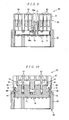
- the retainer 70 is inserted from the front surface of the housing 60 via the hood part 62, and is locked in the hous ing 60 in a temporary locking position (see Fig s. 8A and 8B, 9 through 11) that allows the insertion of the contacts into the contact accommodating cavities 63 and in a main locking position (see Fig s. 12A and 12B, and 13 through 15) that double-locks the contacts.
- the retainer 70 comprises a rectangular flat -plate-form board part 71 that extends in the direction of length (left-right direction in Fig. 8B ) so as to cover the front surface of the contact accommodating part 61, and a plurality of upper -side regulating parts 73a and lower-side regulating parts 73b that respectively extend rearward from the upper and lower ends of the board part 71.
- the respective upper-side regulating parts 73a enter into the spaces 66 formed above the housing lances 64 at the time of main locking, and restrict the upward movement of the housing lances 64, thus ensuring that the contacts of the upper row do not slip out.
- the respective lower-side regulating parts 73b enter into the spaces 66 formed beneath the housing lances 64 at the time of main locking, and restrict the downward movement of the housing lances 64, thus ensuring that the contacts of the lower row do not slip out.
- a plurality of contact passage holes 72 that allow the male type contact parts of the contacts that are accommodated in the contact accommodating cavities 63 to pass through are formed in the board part 71. Furthermore, as is shown clearly in Fig s.
- a plurality of center pieces 74 that enter into the plurality of spaces 67 formed in the contact accommodating part 61 are formed substantially in the central part (in the vertical direction) of the board part 71 of the retainer 70 so that these center pieces 74 extend rearward.
- a pair of temporary locking arms 75 are formed at the left and right ends of the board part 71 so that these arms 75 extend rearward as shown in Figs. 10 and 18 .
- temporary locking projections 76 that are positioned in the rear of the locking projections 68 formed on th e contact accommodating part 61 and thus prevent the retainer 70 from being pulled out in the forward direction when the retainer 70 is in the temporary locking position are formed on the rear ends of the respective temporary locking arms 75.
- the temporary locking projections 76 are designed so that these projections 76 are exposed from the side surfaces of the housing 60 via openings 80 formed in the left and right side walls of the contact accommodating part 61 when the retainer 7 0 is in the main locking position.
- a main locking arm 77 is formed so that this arm 77 extends to the rear substantially in the central part (in the left-right direction) of the board part 71 and between the upper-side regulating parts 73a and center piece s 74 in the vertical direction.
- the main locking arm 77 enters into the through-hole 69a formed in the contact accommodating part 61.
- a m ain locking projection 78 which prevents the retainer 70 from being pushed in toward the rear by being positioned to the front of the locking projection 69b formed in the contact accommodating part 61 when the retainer 70 is in the temporary locking position (as shown in Fig.
- supporting parts 81 that support the side of the back surfaces of the temporary locking arms 75 in the vicinity of the temporary locking projections 76 when the retainer 70 is in the main locking position are formed on the left and right side walls of the contact accommodating part 61.
- the retainer 70 is first inserted from the front surface of the housing 60, and the retainer 70 is positioned in the temporary locking position, as shown in Figs. 9 through 11 .
- the retainer 70 is prevented from being pulled out in the forward direction as a result of the temporary locking projections 76 on the temporary locking arms 75 contacting the rear edges of the locking projections 68 formed on the contact accommodating part 61 as shown in F ig. 10, and the retainer 70 is prevented from being pushed in toward the rear as a result of the main locking projection 78 contacting the front edge of the locking projection 69b formed in the contact accommodating part 61 as shown in Fig. 9 .
- the respective contacts 20 to which electrical wires (not shown in the figures) have been connected are inserted into the respective contact accommodating cavities 63 from the rear side of the housing 60.
- the housing lances 64 are positioned on t he rear sides of the locking parts of the contacts, so that the contacts are tentatively or lightly secured, thus preventing the contacts from slipping out.
- the retainer 70 that is in the temporary locking position is pushed rearward so that the retainer 70 is positioned in the main locking position as shown in Fig. 13 .
- the main locking arm 77 advances rearward inside the through-hole 69a, and the main locking projection 78 contacts the rear edge of the locking projection 69b formed in the contact accommodating part 61, so that the retainer 70 is prevented from being pulled out in the forward direction.
- the upper-side regulating parts 73a of the retainer 70 enter into the spaces 66 formed above the housing lances 64 (as shown in Fig.
- the retainer 70 when the retainer 70 is in the main locking position, the temporary locking projections 76 formed on the temporary locking arms 75 are exposed from the side surfaces of the housing 60 via the openings 80 as shown in Fig. 14 , so that the positions of the temporary locking projections 76 can be visually confirmed from the side surfaces of the housing 60. As a result, the state of the retainer 70 in the main locking position can easily b e confirmed by visual inspection.
- the state of the retainer 70 in the main locking position can also be detected by causing an inspection probe P to contact the side surfaces of the temporary locking projections 76 from the side of the side surfaces of the housing 60 as shown in Fig. 14 , and by measuring the height of the temporary locking projections 76 from a specified reference.
- the supporting parts 81 that support the back surface sides of the temporary locking arms 75 in the vicinity of the temporary locking projections 76 when the retainer 70 is in the main locking position are formed on the side walls of the contact accommodating part 61, even if the inspection probe P is caused to contact the side surfaces of the temporary locking projections 76 from the side of the side surfaces of the housing 60, the re is no retraction of the temporary locking projections 76. Consequently, the state of the retainer 70 in the main locking position can be easily and securely detected. Furthermore, the outer surfaces of the temporary locking projections 76 are formed as flat surfaces that allow surface contact with the inspection probe P.
Landscapes
- Connector Housings Or Holding Contact Members (AREA)
- Details Of Connecting Devices For Male And Female Coupling (AREA)
Claims (1)
- Elektrischer Steckverbinder (1), der Folgendes umfasst:ein isolierendes Gehäuse (10),Kontakte (20), die in dem Gehäuse (10) untergebracht sind, undeinen Halter (30), der von einer Stirnfläche des Gehäuses (10) eingesetzt wird und der an dem Gehäuse (10) verriegelt ist, in einer zeitweiligen Verriegelungsposition, die das Einsetzen von Kontakten (20) in das Gehäuse ermöglicht, und in einer Hauptverriegelungsposition, die sicherstellt, dass die Kontakte daran gehindert werden, aus dem Gehäuse zu gleiten,wobei der Halter (30) Hauptverriegelungsvorsprünge (36) hat, die widerstehen oder verhindern, dass der Halter rückwärts geschoben wird, wenn sich der Halter in der zeitweiligen Verriegelungsposition befindet, und die widerstehen oder verhindern, dass der Halter (30) vorwärts herausgezogen wird, wenn sich der Halter (30) in der Hauptverriegelungsposition befindet, undwobei der Halter (30) ebenfalls zeitweilige Verriegelungsvorsprünge (34) hat, die verhindern, dass der Halter herausgezogen wird, wenn sich der Halter in der zeitweiligen Verriegelungsposition befindet, dadurch gekennzeichnet, dassdie Hauptverriegelungsvorsprünge (36) und die zeitweiligen Verriegelungsvorsprünge (34) jeweils auf Haupt- bzw. zeitweiligen Verriegelungsarmen (35, 33a) angeordnet sind, und dadurch, dassdie Hauptverriegelungsvorsprünge (36) über Seitenflächen des Gehäuses (10) freigelegt sind, wenn sich der Halter (30) in der Hauptverriegelungsposition befindet, wodurch die Hauptverriegelungsvorsprünge (36) für eine Inspektionssonde zugänglich sind,wobei das Gehäuse (10) Stützteile (19a) hat, die Rückflächenseiten der Hauptverriegelungsarme (35) in der Nachbarschaft der Hauptverriegelungsvorsprünge (36) stützen, wenn sich der Halter (30) in der Hauptverriegelungsposition befindet, undwobei Biegungsermöglichungsräume (19b), die ein Biegen der Hauptverriegelungsarme (35) des Halters (30) ermöglichen, in Positionen geformt sind, die weiter vorn angeordnet sind als die Stützteile (19a) des Gehäuses (10).
Priority Applications (1)
| Application Number | Priority Date | Filing Date | Title |
|---|---|---|---|
| EP07118663A EP1873868A1 (de) | 2003-10-16 | 2004-10-11 | Elektrischer Verbinder |
Applications Claiming Priority (2)
| Application Number | Priority Date | Filing Date | Title |
|---|---|---|---|
| JP2003356655A JP3999186B2 (ja) | 2003-10-16 | 2003-10-16 | 電気コネクタ |
| JP2003356655 | 2003-10-16 |
Related Child Applications (1)
| Application Number | Title | Priority Date | Filing Date |
|---|---|---|---|
| EP07118663A Division EP1873868A1 (de) | 2003-10-16 | 2004-10-11 | Elektrischer Verbinder |
Publications (2)
| Publication Number | Publication Date |
|---|---|
| EP1524728A1 EP1524728A1 (de) | 2005-04-20 |
| EP1524728B1 true EP1524728B1 (de) | 2008-07-09 |
Family
ID=34373604
Family Applications (2)
| Application Number | Title | Priority Date | Filing Date |
|---|---|---|---|
| EP04104977A Expired - Lifetime EP1524728B1 (de) | 2003-10-16 | 2004-10-11 | Elektrischer Verbinder |
| EP07118663A Withdrawn EP1873868A1 (de) | 2003-10-16 | 2004-10-11 | Elektrischer Verbinder |
Family Applications After (1)
| Application Number | Title | Priority Date | Filing Date |
|---|---|---|---|
| EP07118663A Withdrawn EP1873868A1 (de) | 2003-10-16 | 2004-10-11 | Elektrischer Verbinder |
Country Status (6)
| Country | Link |
|---|---|
| US (1) | US7112104B2 (de) |
| EP (2) | EP1524728B1 (de) |
| JP (1) | JP3999186B2 (de) |
| CN (1) | CN100521387C (de) |
| ES (1) | ES2309453T3 (de) |
| TW (1) | TWI325658B (de) |
Cited By (1)
| Publication number | Priority date | Publication date | Assignee | Title |
|---|---|---|---|---|
| CN102738631A (zh) * | 2011-03-31 | 2012-10-17 | 住友电装株式会社 | 连接器 |
Families Citing this family (20)
| Publication number | Priority date | Publication date | Assignee | Title |
|---|---|---|---|---|
| JP4554376B2 (ja) * | 2005-01-14 | 2010-09-29 | 矢崎総業株式会社 | コネクタ |
| JP4737543B2 (ja) * | 2006-07-07 | 2011-08-03 | 住友電装株式会社 | コネクタ |
| JP4987624B2 (ja) * | 2007-08-21 | 2012-07-25 | 矢崎総業株式会社 | 分割式コネクタ |
| JP4924454B2 (ja) * | 2008-01-29 | 2012-04-25 | 住友電装株式会社 | コネクタ |
| CN102484332B (zh) * | 2009-07-20 | 2015-09-16 | 富加宜汽车控股公司 | 具有短路杆操作装置的电连接器 |
| JP5201101B2 (ja) * | 2009-07-28 | 2013-06-05 | 住友電装株式会社 | コネクタ |
| JP2011076974A (ja) * | 2009-10-01 | 2011-04-14 | Yazaki Corp | コネクタ |
| US8651901B2 (en) * | 2011-05-04 | 2014-02-18 | Tyco Electronics Corporation | Electrical connector having terminal position assurance |
| US8951066B2 (en) | 2011-07-22 | 2015-02-10 | Lear Corporation | Electrical connector |
| US8721374B2 (en) * | 2011-07-22 | 2014-05-13 | Lear Corporation | Electrical connector |
| US9276345B2 (en) * | 2012-03-16 | 2016-03-01 | Delphi International Operations Luxembourg S.A.R.L. | Electrical connector |
| JP2014093222A (ja) * | 2012-11-05 | 2014-05-19 | Sumitomo Wiring Syst Ltd | コネクタ |
| JP6015628B2 (ja) * | 2013-10-31 | 2016-10-26 | 住友電装株式会社 | コネクタ |
| JP6292468B2 (ja) * | 2014-01-31 | 2018-03-14 | 住友電装株式会社 | コネクタ |
| JP6187873B2 (ja) * | 2014-03-28 | 2017-08-30 | 住友電装株式会社 | コネクタ |
| JP6196961B2 (ja) * | 2014-12-11 | 2017-09-13 | 矢崎総業株式会社 | コネクタ |
| JP6402126B2 (ja) * | 2016-03-03 | 2018-10-10 | 矢崎総業株式会社 | コネクタ装置 |
| JP2019050169A (ja) * | 2017-09-12 | 2019-03-28 | 住友電装株式会社 | コネクタ |
| JP7680898B2 (ja) * | 2021-07-07 | 2025-05-21 | 矢崎総業株式会社 | コネクタ |
| JP7610784B2 (ja) * | 2021-10-27 | 2025-01-09 | 株式会社オートネットワーク技術研究所 | コネクタ、及びコネクタ構成体 |
Family Cites Families (7)
| Publication number | Priority date | Publication date | Assignee | Title |
|---|---|---|---|---|
| JP3022970B2 (ja) | 1989-06-02 | 2000-03-21 | 臼井国際産業株式会社 | 分岐接続用継手本体、継手およびその接続方法 |
| JPH0770334B2 (ja) * | 1989-12-27 | 1995-07-31 | 矢崎総業株式会社 | 端子係止具付コネクタ |
| US5931700A (en) * | 1995-02-06 | 1999-08-03 | Yazaki Corporation | Connector equipped with an insertion detecting member for terminal lugs |
| JP3542710B2 (ja) * | 1998-02-20 | 2004-07-14 | 矢崎総業株式会社 | コネクタ |
| US6290539B1 (en) * | 1999-04-30 | 2001-09-18 | Cardell Corporation | Electrical connector having a two-piece socket portion |
| JP2002008764A (ja) * | 2000-06-27 | 2002-01-11 | Yazaki Corp | コネクタ |
| JP2002025705A (ja) | 2000-07-06 | 2002-01-25 | Sumitomo Wiring Syst Ltd | コネクタ |
-
2003
- 2003-10-16 JP JP2003356655A patent/JP3999186B2/ja not_active Expired - Lifetime
-
2004
- 2004-10-05 TW TW093130096A patent/TWI325658B/zh not_active IP Right Cessation
- 2004-10-11 EP EP04104977A patent/EP1524728B1/de not_active Expired - Lifetime
- 2004-10-11 EP EP07118663A patent/EP1873868A1/de not_active Withdrawn
- 2004-10-11 ES ES04104977T patent/ES2309453T3/es not_active Expired - Lifetime
- 2004-10-13 US US10/964,256 patent/US7112104B2/en not_active Expired - Fee Related
- 2004-10-18 CN CNB2004100857675A patent/CN100521387C/zh not_active Expired - Fee Related
Cited By (2)
| Publication number | Priority date | Publication date | Assignee | Title |
|---|---|---|---|---|
| CN102738631A (zh) * | 2011-03-31 | 2012-10-17 | 住友电装株式会社 | 连接器 |
| CN102738631B (zh) * | 2011-03-31 | 2015-01-07 | 住友电装株式会社 | 连接器 |
Also Published As
| Publication number | Publication date |
|---|---|
| JP2005123030A (ja) | 2005-05-12 |
| TW200529506A (en) | 2005-09-01 |
| CN100521387C (zh) | 2009-07-29 |
| EP1873868A1 (de) | 2008-01-02 |
| CN1610193A (zh) | 2005-04-27 |
| JP3999186B2 (ja) | 2007-10-31 |
| ES2309453T3 (es) | 2008-12-16 |
| EP1524728A1 (de) | 2005-04-20 |
| US7112104B2 (en) | 2006-09-26 |
| US20050112943A1 (en) | 2005-05-26 |
| TWI325658B (en) | 2010-06-01 |
Similar Documents
| Publication | Publication Date | Title |
|---|---|---|
| EP1524728B1 (de) | Elektrischer Verbinder | |
| US4695112A (en) | Printed circuit board, edgeboard connector therefor | |
| US7114997B2 (en) | Electrical connector | |
| US4984998A (en) | High density electrical connector | |
| US4913667A (en) | Connector system with replaceable plugs | |
| US5342221A (en) | Keying system for electrical connectors | |
| US4596436A (en) | Electrical connector housing assembly comprising housing frame containing housing modules | |
| US8210873B2 (en) | Connector | |
| US4640566A (en) | Electrical connector housing | |
| EP0858134B1 (de) | Zusammenbau eines elektrischen Steckverbinders | |
| EP0386742B1 (de) | Elektrischer Verbinder mit Buchsenkontakten verschiedener Grössen und Mittel zur Vermeidung von falschem Anschliessen | |
| US7004792B2 (en) | Electrical connector | |
| EP1560298B1 (de) | Getrennter Steckverbinder und Verbindereinrichtung | |
| EP1335456B1 (de) | Elektrische Verbindungseinrichtung | |
| EP1524727A1 (de) | Elektrischer Verbinder | |
| US4971580A (en) | High density electrical connector with terminal retention latch | |
| US8215984B2 (en) | Electrical connector | |
| US6699069B2 (en) | On-board type connector | |
| EP1801925B1 (de) | Verbinder und Verbinderanordnung | |
| EP0997986B1 (de) | Elektrischer Verbinder | |
| CN112952410B (zh) | 连接器 | |
| US20040192118A1 (en) | Connector | |
| JPH08148228A (ja) | 雌型コネクタ | |
| JP2025140471A (ja) | コネクタ | |
| WO1997044866A2 (en) | Electrical connector assembly |
Legal Events
| Date | Code | Title | Description |
|---|---|---|---|
| PUAI | Public reference made under article 153(3) epc to a published international application that has entered the european phase |
Free format text: ORIGINAL CODE: 0009012 |
|
| AK | Designated contracting states |
Kind code of ref document: A1 Designated state(s): AT BE BG CH CY CZ DE DK EE ES FI FR GB GR HU IE IT LI LU MC NL PL PT RO SE SI SK TR |
|
| AX | Request for extension of the european patent |
Extension state: AL HR LT LV MK |
|
| 17P | Request for examination filed |
Effective date: 20050919 |
|
| AKX | Designation fees paid |
Designated state(s): ES FR GB |
|
| REG | Reference to a national code |
Ref country code: DE Ref legal event code: 8566 |
|
| 17Q | First examination report despatched |
Effective date: 20060213 |
|
| 17Q | First examination report despatched |
Effective date: 20060213 |
|
| GRAP | Despatch of communication of intention to grant a patent |
Free format text: ORIGINAL CODE: EPIDOSNIGR1 |
|
| GRAS | Grant fee paid |
Free format text: ORIGINAL CODE: EPIDOSNIGR3 |
|
| GRAA | (expected) grant |
Free format text: ORIGINAL CODE: 0009210 |
|
| AK | Designated contracting states |
Kind code of ref document: B1 Designated state(s): ES FR GB |
|
| REG | Reference to a national code |
Ref country code: GB Ref legal event code: FG4D |
|
| REG | Reference to a national code |
Ref country code: ES Ref legal event code: FG2A Ref document number: 2309453 Country of ref document: ES Kind code of ref document: T3 |
|
| PGFP | Annual fee paid to national office [announced via postgrant information from national office to epo] |
Ref country code: ES Payment date: 20081027 Year of fee payment: 5 |
|
| PLBE | No opposition filed within time limit |
Free format text: ORIGINAL CODE: 0009261 |
|
| STAA | Information on the status of an ep patent application or granted ep patent |
Free format text: STATUS: NO OPPOSITION FILED WITHIN TIME LIMIT |
|
| 26N | No opposition filed |
Effective date: 20090414 |
|
| PGFP | Annual fee paid to national office [announced via postgrant information from national office to epo] |
Ref country code: GB Payment date: 20081029 Year of fee payment: 5 |
|
| REG | Reference to a national code |
Ref country code: FR Ref legal event code: CD |
|
| PG25 | Lapsed in a contracting state [announced via postgrant information from national office to epo] |
Ref country code: GB Free format text: LAPSE BECAUSE OF NON-PAYMENT OF DUE FEES Effective date: 20091011 |
|
| REG | Reference to a national code |
Ref country code: ES Ref legal event code: FD2A Effective date: 20110329 |
|
| PG25 | Lapsed in a contracting state [announced via postgrant information from national office to epo] |
Ref country code: ES Free format text: LAPSE BECAUSE OF NON-PAYMENT OF DUE FEES Effective date: 20110316 |
|
| PG25 | Lapsed in a contracting state [announced via postgrant information from national office to epo] |
Ref country code: ES Free format text: LAPSE BECAUSE OF NON-PAYMENT OF DUE FEES Effective date: 20091012 |
|
| REG | Reference to a national code |
Ref country code: FR Ref legal event code: PLFP Year of fee payment: 12 |
|
| PGFP | Annual fee paid to national office [announced via postgrant information from national office to epo] |
Ref country code: FR Payment date: 20151019 Year of fee payment: 12 |
|
| REG | Reference to a national code |
Ref country code: FR Ref legal event code: ST Effective date: 20170630 |
|
| PG25 | Lapsed in a contracting state [announced via postgrant information from national office to epo] |
Ref country code: FR Free format text: LAPSE BECAUSE OF NON-PAYMENT OF DUE FEES Effective date: 20161102 |