EP1525399B1 - Pompe a diaphragme - Google Patents
Pompe a diaphragme Download PDFInfo
- Publication number
- EP1525399B1 EP1525399B1 EP04714736A EP04714736A EP1525399B1 EP 1525399 B1 EP1525399 B1 EP 1525399B1 EP 04714736 A EP04714736 A EP 04714736A EP 04714736 A EP04714736 A EP 04714736A EP 1525399 B1 EP1525399 B1 EP 1525399B1
- Authority
- EP
- European Patent Office
- Prior art keywords
- diaphragm
- support ribs
- chamber wall
- diaphragm pump
- pumping chamber
- Prior art date
- Legal status (The legal status is an assumption and is not a legal conclusion. Google has not performed a legal analysis and makes no representation as to the accuracy of the status listed.)
- Expired - Lifetime
Links
- 238000005086 pumping Methods 0.000 claims description 23
- 230000033001 locomotion Effects 0.000 claims description 12
- 239000012528 membrane Substances 0.000 description 36
- 230000006835 compression Effects 0.000 description 2
- 238000007906 compression Methods 0.000 description 2
- 230000003014 reinforcing effect Effects 0.000 description 2
- 230000000694 effects Effects 0.000 description 1
- 239000013013 elastic material Substances 0.000 description 1
- 239000010410 layer Substances 0.000 description 1
- 239000000463 material Substances 0.000 description 1
- 230000002093 peripheral effect Effects 0.000 description 1
- 239000002356 single layer Substances 0.000 description 1
Images
Classifications
-
- F—MECHANICAL ENGINEERING; LIGHTING; HEATING; WEAPONS; BLASTING
- F04—POSITIVE - DISPLACEMENT MACHINES FOR LIQUIDS; PUMPS FOR LIQUIDS OR ELASTIC FLUIDS
- F04B—POSITIVE-DISPLACEMENT MACHINES FOR LIQUIDS; PUMPS
- F04B43/00—Machines, pumps, or pumping installations having flexible working members
- F04B43/0009—Special features
- F04B43/0054—Special features particularities of the flexible members
Definitions
- the invention relates to a diaphragm pump with an oscillating during the pumping movements between a lower and a top dead center working diaphragm, which defines a pump space between itself and a preferably concavely curved pump chamber wall, wherein the working diaphragm rests at top dead center on the pump chamber wall.
- Diaphragm pumps of the type mentioned are already known in various designs. If such diaphragm pumps are operated in the lower vacuum range, there is the danger that the working diaphragm will bulge due to the differential pressure load occurring between the upper and lower diaphragm sides and in this way reduce the pumping chamber volume. Especially in this deeper vacuum range, large pressure differences occur between the membrane top and bottom. While the membrane underside generally bears the atmospheric pressure, the respective evacuation pressure acts on the upper side of the membrane, the maximum pressure difference resulting from the atmospheric pressure minus the end pressure of the diaphragm pump.
- a membrane pump with a working diaphragm made of elastic material which has a receiving cavity for a connecting rod in its reinforced central area and is held on the outside with a clamping edge on the pump housing.
- a plurality of radially spaced-apart and circumferential circumferential ribs are provided radially outwardly adjacent to the reinforced central region of the diaphragm, by which a higher strength of the diaphragm against pressure while retaining the flexibility of the central region bounding outer ring zone of the membrane is desired.
- the diaphragm pump according to the invention has a working diaphragm which has an inner and an outer annular zone, wherein between these annular zones a stiffened and during the pumping movements non-deformable membrane region is arranged. While the inner and outer annular zones form two hinge regions which allow the working diaphragm to bend in these regions due to the stroke, the undeformable diaphragm region in between counteracts undesirable and performance-reducing bulging of the working diaphragm under increased differential pressure loads.
- the stiffening of the membrane is carried out in its non-deformable membrane area such that the working membrane still rests unhindered at the top dead center on the preferably concavely curved pump chamber wall.
- the working membrane is stiffened according to the invention in its non-deformable membrane region by means of radially oriented and circumferentially spaced support ribs, which are arranged on the side facing away from the pump chamber wall diaphragm bottom. Since the working diaphragm of the diaphragm pump according to the invention has reinforcing ribs stiffening on its underside facing away from the pump chamber wall, it can be formed in its non-deformable membrane region from a single-layer material layer.
- the support or reinforcing ribs are geometric and dimensionally designed so that, for example, even at low end pressures the atmospheric pressure prevailing during the intake stroke on the membrane underside can not bend the membrane in its non-deformable membrane area.
- the support ribs stiffening this membrane area are delimited on both sides by the deformable annular zones which form the hinge areas required for the flexing movements of the membrane during the pumping movements.
- the support ribs can be arranged in the radial direction on the membrane underside.
- the greater the angle of the support ribs to the radial the less the radial deformation of the support ribs and the deformation of the compression space associated with an increase in the harmful space and with a reduction in the final vacuum facing contour of the ribs.
- a development according to the invention provides that the support ribs have a curved longitudinal extension and are thus arranged practically helically on the diaphragm underside.
- the ribs have a straight longitudinal extent, it can be advantageous if the support ribs preferably deviate up to ⁇ 30 ° from the radial.
- circumferentially spaced support ribs have the same direction of curvature or deviation from the radial.
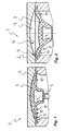
- a diaphragm pump 1 is shown in the region of its pump head 2.
- the membrane pump 1 has a working diaphragm 3, which is clamped at its peripheral edge in the pump head.
- a central fixing core 4 is formed, which is connected to the connecting rod 5 of a crank drive, not shown here.
- the pumping movements between the in Fig. 1 shown top dead center and the in Fig. 2 shown bottom dead center oscillating working diaphragm 3 defines between itself and a concave pump chamber wall 6 a pump space. 7
- the working diaphragm pump 1 shown here for example as a backing pump of a turbomolecular pump
- the working diaphragm 3 does not buckle under the differential pressure load which occurs between the upper and lower diaphragm sides and thereby decisively reduces the pumping chamber volume
- the working diaphragm 3 has a stiffened annular zone which is substantially non-deformable during the pumping movements.
- This non-deformable membrane area is bounded by an inner annular zone 8 and an outer annular zone 9, which serve as deformable hinge areas during the pumping motions.
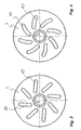
- radially oriented support ribs 10 are provided here, which are arranged on the pump chamber wall 6 facing away from the membrane bottom. These support ribs 10 are circumferentially spaced at regular intervals from each other. So that the working diaphragm 3 - like Fig. 1 shows - at the top dead center of the pump chamber wall 6 can preferably invest over the entire surface, the pump room wall 6 facing side of the support ribs 10 is adapted to the contour of the pump chamber wall 6.
- the support ribs 10 may have a straight longitudinal extent. In order to favor the stiffening of the working membrane 3 in the non-deformable annular zone, it may be advantageous if the support ribs 10 preferably deviate up to ⁇ 30 ° from the radial. It is also possible that the support ribs - as in Fig. 4 is shown - have a curved longitudinal extent and are arranged practically helically on the diaphragm underside.
Landscapes
- Engineering & Computer Science (AREA)
- Mechanical Engineering (AREA)
- General Engineering & Computer Science (AREA)
- Reciprocating Pumps (AREA)
Claims (7)
- Pompe à diaphragme (1), avec un diaphragme de travail (3) oscillant entre un point mort bas et un point mort haut pendant les mouvements de pompage, qui délimite une chambre de pompage (7) entre lui-même et une paroi (6) de chambre de pompage et qui s'applique au point mort haut contre la paroi (6) de chambre de pompage, le diaphragme de travail (3) présentant une zone annulaire intérieure (8) et une zone annulaire extérieure (9) qui peuvent être déformées pendant les mouvements de pompage, sachant qu'une région de diaphragme rigidifiée et essentiellement indéformable pendant les mouvements de pompage est disposée entre ces zones annulaires (8, 9), et le diaphragme de travail (3) étant, dans sa région de diaphragme indéformable, rigidifié au moyen de nervures de soutien (10) orientées radialement et distantes les unes des autres en direction circonférentielle, qui sont disposées sur le dessous du diaphragme, opposé à la paroi (6) de chambre de pompage.
- Pompe à diaphragme selon la revendication 1, caractérisée en ce que la paroi de chambre de pompage est à bombement concave.
- Pompe à diaphragme selon la revendication 1 ou 2, caractérisée en ce que les nervures de soutien (10) présentent une étendue longitudinale courbe.
- Pompe à diaphragme selon la revendication 1 ou 2, caractérisée en ce que les nervures de soutien (10) présentent une étendue longitudinale rectiligne.
- Pompe à diaphragme selon l'une des revendications 1 à 4, caractérisée en ce que les nervures de soutien (10) s'écartent de préférence de plus/moins 30° par rapport à la radiale.
- Pompe à diaphragme selon l'une des revendications 1 à 5, caractérisée en ce que les nervures de soutien (10) mutuellement distantes en direction circonférentielle possèdent la même direction de courbure ou le même écart par rapport à la radiale.
- Pompe à diaphragme selon l'une des revendications 1 à 6, caractérisée en ce que le côté des nervures de soutien (10) qui est tourné vers la paroi (6) de chambre de pompage est d'une forme adaptée au contour de la paroi (6) de chambre de pompage.
Applications Claiming Priority (3)
| Application Number | Priority Date | Filing Date | Title |
|---|---|---|---|
| DE10312899A DE10312899A1 (de) | 2003-03-22 | 2003-03-22 | Membranpumpe |
| DE10312899 | 2003-03-22 | ||
| PCT/EP2004/001887 WO2004083639A1 (fr) | 2003-03-22 | 2004-02-26 | Pompe a diaphragme |
Publications (2)
| Publication Number | Publication Date |
|---|---|
| EP1525399A1 EP1525399A1 (fr) | 2005-04-27 |
| EP1525399B1 true EP1525399B1 (fr) | 2008-06-25 |
Family
ID=32946075
Family Applications (1)
| Application Number | Title | Priority Date | Filing Date |
|---|---|---|---|
| EP04714736A Expired - Lifetime EP1525399B1 (fr) | 2003-03-22 | 2004-02-26 | Pompe a diaphragme |
Country Status (5)
| Country | Link |
|---|---|
| US (1) | US7363850B2 (fr) |
| EP (1) | EP1525399B1 (fr) |
| JP (1) | JP2006520868A (fr) |
| DE (2) | DE10312899A1 (fr) |
| WO (1) | WO2004083639A1 (fr) |
Cited By (1)
| Publication number | Priority date | Publication date | Assignee | Title |
|---|---|---|---|---|
| US12061487B2 (en) | 2022-06-01 | 2024-08-13 | Husqvarna | Pressure reducer |
Families Citing this family (14)
| Publication number | Priority date | Publication date | Assignee | Title |
|---|---|---|---|---|
| GB0409446D0 (en) | 2004-04-28 | 2004-06-02 | Smith & Nephew | Apparatus |
| FR2921443A1 (fr) * | 2007-09-20 | 2009-03-27 | Fresenius Vial Soc Par Actions | Pompe peristaltique lineaire a doigts ainsi qu'une membrane et un doigt pour une telle pompe |
| ES2776709T3 (es) | 2007-11-21 | 2020-07-31 | Smith & Nephew | Apósito para heridas |
| GB0723855D0 (en) | 2007-12-06 | 2008-01-16 | Smith & Nephew | Apparatus and method for wound volume measurement |
| JP4792598B2 (ja) | 2008-03-24 | 2011-10-12 | 株式会社日本製鋼所 | 水素透過モジュールおよびその使用方法 |
| US8444596B2 (en) * | 2009-06-22 | 2013-05-21 | Lansinoh Laboratories, Inc. | Breast milk collection apparatus and components thereof |
| GB201015656D0 (en) | 2010-09-20 | 2010-10-27 | Smith & Nephew | Pressure control apparatus |
| US9067003B2 (en) | 2011-05-26 | 2015-06-30 | Kalypto Medical, Inc. | Method for providing negative pressure to a negative pressure wound therapy bandage |
| US9084845B2 (en) | 2011-11-02 | 2015-07-21 | Smith & Nephew Plc | Reduced pressure therapy apparatuses and methods of using same |
| US9901664B2 (en) | 2012-03-20 | 2018-02-27 | Smith & Nephew Plc | Controlling operation of a reduced pressure therapy system based on dynamic duty cycle threshold determination |
| US9427505B2 (en) | 2012-05-15 | 2016-08-30 | Smith & Nephew Plc | Negative pressure wound therapy apparatus |
| AU2015370583B2 (en) | 2014-12-22 | 2020-08-20 | Smith & Nephew Plc | Negative pressure wound therapy apparatus and methods |
| DE102019135153A1 (de) * | 2019-12-19 | 2021-06-24 | Prominent Gmbh | Dosierpumpe mit Dosiermembran |
| DE102020126241B4 (de) * | 2020-10-07 | 2026-03-19 | Alfmeier Präzision SE | Membrananordnung mit um den Membrankörper umlaufendem Ring sowie Sitzanordnung und Pumpenanordnung |
Family Cites Families (7)
| Publication number | Priority date | Publication date | Assignee | Title |
|---|---|---|---|---|
| US3947156A (en) | 1972-03-08 | 1976-03-30 | Erich Becker | Diaphragm pump, particularly for the generation of vacuum |
| WO1993018305A1 (fr) | 1992-03-05 | 1993-09-16 | Joe Santa & Associates Pty. Limited | Pompe, soupape de commande et diaphragme |
| US5349896A (en) | 1993-06-14 | 1994-09-27 | W. L. Gore & Associates, Inc. | Pump diaphragm |
| DE19510828C2 (de) | 1995-03-24 | 1998-12-24 | Knf Neuberger Gmbh | Membranpumpe mit einer Formmembran |
| DE19834468C1 (de) | 1998-07-30 | 2000-02-24 | Asf Thomas Ind Gmbh | Membrane für eine Membranpumpe |
| DE19906317C1 (de) * | 1999-02-16 | 2000-10-19 | Knf Flodos Ag Sursee | Membranpumpe |
| ATE368181T1 (de) * | 2001-01-02 | 2007-08-15 | Medela Holding Ag | Membranpumpe |
-
2003
- 2003-03-22 DE DE10312899A patent/DE10312899A1/de not_active Withdrawn
-
2004
- 2004-02-26 DE DE502004007433T patent/DE502004007433D1/de not_active Expired - Lifetime
- 2004-02-26 WO PCT/EP2004/001887 patent/WO2004083639A1/fr not_active Ceased
- 2004-02-26 EP EP04714736A patent/EP1525399B1/fr not_active Expired - Lifetime
- 2004-02-26 JP JP2006504472A patent/JP2006520868A/ja active Pending
- 2004-02-26 US US10/541,350 patent/US7363850B2/en not_active Expired - Lifetime
Cited By (1)
| Publication number | Priority date | Publication date | Assignee | Title |
|---|---|---|---|---|
| US12061487B2 (en) | 2022-06-01 | 2024-08-13 | Husqvarna | Pressure reducer |
Also Published As
| Publication number | Publication date |
|---|---|
| JP2006520868A (ja) | 2006-09-14 |
| DE502004007433D1 (de) | 2008-08-07 |
| US20060039806A1 (en) | 2006-02-23 |
| DE10312899A1 (de) | 2004-10-07 |
| WO2004083639A1 (fr) | 2004-09-30 |
| US7363850B2 (en) | 2008-04-29 |
| EP1525399A1 (fr) | 2005-04-27 |
Similar Documents
| Publication | Publication Date | Title |
|---|---|---|
| EP1525399B1 (fr) | Pompe a diaphragme | |
| DE4007932C2 (fr) | ||
| EP0733802B1 (fr) | Pompe à membrane façonnée | |
| DE19906317C1 (de) | Membranpumpe | |
| DE2546588C2 (de) | Dichtung für eine Welle | |
| EP0910745B1 (fr) | Membrane pour une pompe a membrane | |
| DE69003955T2 (de) | Pumpengehäuse. | |
| DE2502566B2 (de) | Membranpumpe | |
| EP4328448B1 (fr) | Pompe à membrane | |
| DE102007039964A1 (de) | Hochdruck-Doppelmembranpumpe und Membranelement für eine solche Pumpe | |
| DE4200495A1 (de) | Kolben mit konischer stange | |
| DE3233854A1 (de) | Pendelkolbenpumpe | |
| DE2421487A1 (de) | Membranpumpe | |
| DE20304621U1 (de) | Membranpumpe | |
| EP2954208B1 (fr) | Compresseur à piston asymétrique | |
| WO1998022713A1 (fr) | Pompe a membrane | |
| DE102012008805A1 (de) | Vakuumventilbalg | |
| DE9406216U1 (de) | Membranpumpe mit einer Formmembran | |
| DE3813500A1 (de) | Membranpumpe oder membrankompressor | |
| DE29505021U1 (de) | Membranpumpe mit einer Formmembran | |
| DE102006055556B4 (de) | Membranpumpe | |
| DE29620094U1 (de) | Membranpumpe | |
| DE9410116U1 (de) | Membranpumpe mit einer Formmembran | |
| EP4675104A1 (fr) | Membrane composite, notamment pour pompes à membrane | |
| DE2350660A1 (de) | Schnellanschluss, insbesondere fuer fahrradpumpen |
Legal Events
| Date | Code | Title | Description |
|---|---|---|---|
| PUAI | Public reference made under article 153(3) epc to a published international application that has entered the european phase |
Free format text: ORIGINAL CODE: 0009012 |
|
| 17P | Request for examination filed |
Effective date: 20050225 |
|
| AK | Designated contracting states |
Kind code of ref document: A1 Designated state(s): AT BE BG CH CY CZ DE DK EE ES FI FR GB GR HU IE IT LI LU MC NL PT RO SE SI SK TR |
|
| AX | Request for extension of the european patent |
Extension state: AL LT LV MK |
|
| DAX | Request for extension of the european patent (deleted) | ||
| RBV | Designated contracting states (corrected) |
Designated state(s): DE FR GB |
|
| GRAP | Despatch of communication of intention to grant a patent |
Free format text: ORIGINAL CODE: EPIDOSNIGR1 |
|
| GRAS | Grant fee paid |
Free format text: ORIGINAL CODE: EPIDOSNIGR3 |
|
| GRAA | (expected) grant |
Free format text: ORIGINAL CODE: 0009210 |
|
| AK | Designated contracting states |
Kind code of ref document: B1 Designated state(s): DE FR GB |
|
| REG | Reference to a national code |
Ref country code: GB Ref legal event code: FG4D Free format text: NOT ENGLISH |
|
| REF | Corresponds to: |
Ref document number: 502004007433 Country of ref document: DE Date of ref document: 20080807 Kind code of ref document: P |
|
| PLBE | No opposition filed within time limit |
Free format text: ORIGINAL CODE: 0009261 |
|
| STAA | Information on the status of an ep patent application or granted ep patent |
Free format text: STATUS: NO OPPOSITION FILED WITHIN TIME LIMIT |
|
| 26N | No opposition filed |
Effective date: 20090326 |
|
| REG | Reference to a national code |
Ref country code: FR Ref legal event code: PLFP Year of fee payment: 13 |
|
| REG | Reference to a national code |
Ref country code: FR Ref legal event code: PLFP Year of fee payment: 14 |
|
| REG | Reference to a national code |
Ref country code: FR Ref legal event code: PLFP Year of fee payment: 15 |
|
| PGFP | Annual fee paid to national office [announced via postgrant information from national office to epo] |
Ref country code: FR Payment date: 20230217 Year of fee payment: 20 |
|
| PGFP | Annual fee paid to national office [announced via postgrant information from national office to epo] |
Ref country code: GB Payment date: 20230221 Year of fee payment: 20 Ref country code: DE Payment date: 20230209 Year of fee payment: 20 |
|
| P01 | Opt-out of the competence of the unified patent court (upc) registered |
Effective date: 20230601 |
|
| REG | Reference to a national code |
Ref country code: DE Ref legal event code: R071 Ref document number: 502004007433 Country of ref document: DE |
|
| REG | Reference to a national code |
Ref country code: GB Ref legal event code: PE20 Expiry date: 20240225 |
|
| PG25 | Lapsed in a contracting state [announced via postgrant information from national office to epo] |
Ref country code: GB Free format text: LAPSE BECAUSE OF EXPIRATION OF PROTECTION Effective date: 20240225 |