EP1531120B1 - Pedalvorrichtung für Fahrräder - Google Patents
Pedalvorrichtung für Fahrräder Download PDFInfo
- Publication number
- EP1531120B1 EP1531120B1 EP04021353A EP04021353A EP1531120B1 EP 1531120 B1 EP1531120 B1 EP 1531120B1 EP 04021353 A EP04021353 A EP 04021353A EP 04021353 A EP04021353 A EP 04021353A EP 1531120 B1 EP1531120 B1 EP 1531120B1
- Authority
- EP
- European Patent Office
- Prior art keywords
- bicycle
- cleat
- pedal
- clamping member
- bicycle pedal
- Prior art date
- Legal status (The legal status is an assumption and is not a legal conclusion. Google has not performed a legal analysis and makes no representation as to the accuracy of the status listed.)
- Expired - Lifetime
Links
- 230000008878 coupling Effects 0.000 claims description 42
- 238000010168 coupling process Methods 0.000 claims description 42
- 238000005859 coupling reaction Methods 0.000 claims description 42
- 230000000712 assembly Effects 0.000 description 17
- 238000000429 assembly Methods 0.000 description 17
- 230000007246 mechanism Effects 0.000 description 8
- 238000010276 construction Methods 0.000 description 4
- 239000000463 material Substances 0.000 description 3
- 238000004519 manufacturing process Methods 0.000 description 2
- 229910000838 Al alloy Inorganic materials 0.000 description 1
- 230000009471 action Effects 0.000 description 1
- 230000001154 acute effect Effects 0.000 description 1
- 230000008859 change Effects 0.000 description 1
- 230000002860 competitive effect Effects 0.000 description 1
- 239000003562 lightweight material Substances 0.000 description 1
- 230000007257 malfunction Effects 0.000 description 1
- 230000036316 preload Effects 0.000 description 1
- 230000001681 protective effect Effects 0.000 description 1
- 239000010935 stainless steel Substances 0.000 description 1
- 229910001220 stainless steel Inorganic materials 0.000 description 1
Images







Classifications
-
- B—PERFORMING OPERATIONS; TRANSPORTING
- B62—LAND VEHICLES FOR TRAVELLING OTHERWISE THAN ON RAILS
- B62M—RIDER PROPULSION OF WHEELED VEHICLES OR SLEDGES; POWERED PROPULSION OF SLEDGES OR SINGLE-TRACK CYCLES; TRANSMISSIONS SPECIALLY ADAPTED FOR SUCH VEHICLES
- B62M3/00—Construction of cranks operated by hand or foot
- B62M3/08—Pedals
- B62M3/086—Attachments between shoe and pedal other than toe clips, e.g. cleats
-
- Y—GENERAL TAGGING OF NEW TECHNOLOGICAL DEVELOPMENTS; GENERAL TAGGING OF CROSS-SECTIONAL TECHNOLOGIES SPANNING OVER SEVERAL SECTIONS OF THE IPC; TECHNICAL SUBJECTS COVERED BY FORMER USPC CROSS-REFERENCE ART COLLECTIONS [XRACs] AND DIGESTS
- Y10—TECHNICAL SUBJECTS COVERED BY FORMER USPC
- Y10T—TECHNICAL SUBJECTS COVERED BY FORMER US CLASSIFICATION
- Y10T74/00—Machine element or mechanism
- Y10T74/21—Elements
- Y10T74/2164—Cranks and pedals
- Y10T74/2168—Pedals
- Y10T74/217—Pedals with toe or shoe clips
Definitions
- This invention generally relates to a bicycle pedal assembly. More specifically, the present invention relates clipless or step-in bicycle pedal assembly, which has cleats that are releasble coupled to a pair of bicycle pedals.
- Bicycling is becoming an increasingly more popular form of recreation as well as a means of transportation. Moreover, bicycling has become a very popular competitive sport for both amateurs and professionals. Whether the bicycle is used for recreation, transportation or competition, the bicycle industry is constantly improving the various components of the bicycle as well as the frame of the bicycle. One component that has been extensively redesigned is the bicycle pedal.
- bicycle pedals have been designed for specific purposes such as for pleasure, off road biking, road racing, etc.
- One particular type of bicycle pedal which is gaining more popularity, is the step-in or clipless pedal, which releasably engages a cleat secured to the sole of a cyclist's shoe.
- the clipless pedal has a pedal spindle that can be mounted on the crank of a bicycle, a pedal body that is rotatably supported on this pedal spindle, and a cleat engagement mechanism.
- a cleat engagement mechanism is formed on both sides of the pedal body for engaging a cleat.
- a road-racing pedal typically only has a cleat engagement mechanism on one side of the pedal body. In either case, in these types of bicycle pedals, the rider steps onto the pedal and the cleat engagement mechanism automatically grips on to the cleat secured to the bottom of the cyclist's shoe.
- step-in or clipless pedal such as expressed under US 6,151,989 , EP 0 619219 A1 , US 5,419,218 or US 5 131 291 , the shoe and the pedal are in a state of constant engagement when the cleat is engaged in the cleat clamping members, so the pedaling force can be transmitted efficiently to the pedals.
- step-in or clipless pedals are widely employed on racing bicycles used in road racing and mountain bike racing.
- the cyclist When attaching the cyclist's shoe to the step-in or clipless pedal via the cleat, the cyclist moves the shoe obliquely downwardly and forwardly relative to the pedal body such that the front end of the cleat engages a front hook or clamping member of the pedal body.
- the cyclist places the rear end of the cleat in contact with a guide portion of the rear hook or clamping member of the pedal body. In this position, the cyclist presses the shoe downwardly against the pedal to cause the rear hook or clamping member to initially pivot rearwardly against the force of a spring to move the rear hook or clamping member to a cleat releasing position.
- the rear end of the cleat then enters a position opposite a back face of the rear hook or clamping member. Then, the rear hook or clamping member returns under the force of a biasing member or spring so that the rear hook or clamping member engages the rear end of the cleat. This engagement fixes the cyclist's shoe to the pedal via the cleat.
- the cyclist When releasing the shoe from the pedal, the cyclist will typically turn the shoe about an axis perpendicular or approximately perpendicular to the tread of the pedal, using the front end of the cleat as a pivoting point. As a result of this pivoting action, the rear hook or clamping member is pivoted rearwardly against the force of the spring to a cleat releasing position to release the shoe. It is important that the cleat does not inadvertently release the pedal during normal pedaling. Some of these prior step-in or clipless pedals can inadvertently release the cleat during normal pedaling if the spring force on the rear clamping member is set too low.
- One object of the present invention is to provide a bicycle pedal assembly that is configured and arranged such that the release force can be adjusted without an adjustment mechanism for the clamping members.
- Another object of the present invention is to provide a step-in bicycle pedal assembly that is relatively lightweight and malfunction free.
- Yet another object of the present invention is to provide a step-in bicycle pedal assembly that is relatively simple and inexpensive to manufacture.
- the foregoing objects can basically be achieved by providing a bicycle pedal assembly comprising a bicycle pedal and a pair of bicycle cleat.
- the bicycle pedal basically comprises a pedal shaft, a pedal body, a front clamping member and a rear clamping member.
- the pedal shaft has a center rotational axis.
- the pedal body is rotatably coupled to the pedal shaft about the center rotational axis of the pedal shaft.
- the pedal body has a first end and a second end with a center plane extending between the first and second ends and passing through the center rotational axis of the pedal shaft.
- the front clamping member is coupled to the first end of the pedal body.
- the front clamping member has a front cleat engagement surface facing towards the center plane of the pedal body.
- the rear clamping member is coupled to the second end of the pedal body.
- the rear clamping member has a rear cleat engagement surface facing towards the center plane of the pedal body.
- the first bicycle shoe cleat includes first front and rear attachment portions configured and arranged to cooperate with the front and rear clamping members to release the first bicycle shoe cleat from a cleat engaged position to a cleat released position upon application of a first predetermined amount of outward twisting force.
- the second bicycle shoe cleat includes second front and rear attachment portions configured and arranged to cooperate with the front and rear clamping members to release the second bicycle shoe cleat from the cleat engaged position to the cleat released position upon application of a second predetermined amount of outward twisting force that is higher than the first predetermined amount of outward twisting force.
- a bicycle 10 is illustrated that is equipped with a left bicycle pedal 12a and a right bicycle pedal 12b in accordance with a first embodiment of the present invention.
- the bicycle the pedals 12a and 12b are fixedly coupled to a pair of bicycle crank arms 14a and 14b of a bicycle 10 for rotation therewith.
- the left and right bicycle pedals 12a and 12b selectively engage a pair of cleats A and B.
- the left and right bicycle pedals 12a and 12b and the cleats A and B that form a bicycle pedal assembly in accordance with a first embodiment of the present invention.
- the first and second bicycle shoe cleats A and B are preferably fixedly coupled to a pair of bicycle shoes in a conventional manner (e.g., a pair of screws) to releasably couple the cyclist's foot to the bicycle pedals 12a and 12b.
- the bicycle pedals 12a and 12b are especially designed for use with off-road bicycles as opposed to use with a road bicycle.
- the features of the bicycle pedals 12a and 12b can be used in the construction of a road type of bicycle pedal if needed and/or desired.
- the bicycle pedals 12a and 12b can be designed such that the first and second bicycle shoe cleats A and B can only be coupled to one side of the bicycle pedals 12a and 12b.
- the cleats A and B are engaged with the bicycle pedals 12a and 12b by pressing the cleats A and B into the pedals 12a and 12b with a forward and downward motion. This releasably locks the cleats A and B to the pedals 12a and 12b.
- the cleats A and B can be released from the pedals 12a and 12b by twisting the heel of the shoe to the outside of pedals 12a and 12b as discussed below in more detail.
- the first and second bicycle shoe cleats A and B are configured and arranged to selectively cooperate with the bicycle pedals 12a and 12b such that two different release forces can be attained using a single pair of cleats A and B.
- the first and second bicycle shoe cleats A and B are configured and arranged to release upon application of a first predetermined amount of outward twisting force F1 when the first bicycle shoe cleat A is engaged with the left bicycle pedal 12a and the second bicycle shoe cleat B is engaged with the right bicycle pedal 12b.
- the first and second bicycle shoe cleats A and B are configured and arranged to release upon application of a second predetermined amount of outward twisting force F2 that is higher than the first predetermined amount of outward twisting force F1 when the first bicycle shoe cleat A is engaged with the right bicycle pedal 12b and the second bicycle shoe cleat B is engaged with the left bicycle pedal 12a.
- the left bicycle pedal 12a is a mirror image of the right bicycle pedal 12b. It will be apparent to those skilled in the art from this disclosure that the description of the left bicycle pedal 12a also applies to the right bicycle pedal 12b and vice a versa. Thus, the same reference numerals will be used to describe both the left and right pedals 12a and 12b. Moreover, the left bicycle pedal 12a will not be discussed or illustrated in further detail herein for the sake of brevity.
- the left and the right bicycle pedals 12a and 12b basically each includes a pedal shaft or spindle 21, a pedal body 22, a pair of front (first) clamping members 23 pivotally coupled to the pedal body 22 by a pair of pivot pins 24, a pair of rear (second) clamping members 25, a pair of spring holders 26 and a pair of biasing members 28.
- the pedal body 22 preferably includes two pairs of pedal body covers 30 that overlie a center upper portion of the pedal body 22 to protect the pedal body 22 from scratches.
- the pedals 12a and 12b have an overall length X and an overall height Y as seen in Figure 8 .
- the pedal spindles 21 are fastened to the crank arms 14a and 14b of the bicycle 10, with the pedal bodies 22 being rotatably coupled to the pedal spindle 21 for supporting the rider's feet.
- the cleats A and B are fixedly attached to the bicycle shoes, which in turn are releasably attached to the pedal bodies 22 via one of the pairs of the front and rear clamping members 23 and 25.
- the pedal spindle 21 is a multi-step spindle having numerous stepped portions.
- the pedal spindle 21 has a first end 31 with threads formed thereon for threadedly coupling bicycle pedal to the crank arm 14a or 14b in a conventional manner.
- the other end of the pedal spindle 21 rotatably supports the pedal body 22 in a conventional manner.
- the pedal body 22 can freely rotate about the center rotational axis R of the pedal spindle 21. Since the pedal spindle 21 is relatively conventional and its specific construction is not critical to the present invention, the construction of the pedal spindle 21 will not be discussed in detail herein.
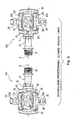
- the pedal body 22 is an H-shaped member (see Figure 12 ) that basically includes a center tubular portion 41, an inner side mounting portion 42 and an outer side mounting portion 43.
- the pedal body 22 is a rigid member that is preferably made as a one-piece, unitary member from a lightweight material such as an aluminum alloy.
- the pedal body 22 is rotatably coupled to the pedal spindle 21 for rotation about a center rotational axis R of the pedal spindle 21.
- the center tubular portion 41 has a stepped bore 44 (see Figure 14 ) for receiving the pedal spindle 21 for rotation about the center rotational axis R.
- the side mounting portions 42 and 43 are configured and arranged to pivotal support the clamping members 23 and 25 via the pivot pins 24.
- the inner side mounting portion 42 extends in a forward and backward direction from an inner end of the center tubular portion 41.
- the side mounting portions 42 and 43 are provided with a pair of cover receiving recesses 45 on each of the sides of the pedal body 22.
- the cover receiving recesses 45 are configured and arranged to receive the pedal body covers 30, respectively.
- the inner side mounting portion 42 has a pair of threaded holes or bores 46 that threadedly receive the pivot pins 24 therein.
- the outer side mounting portion 43 extends in a forward and backward direction from an outer end of the center tubular portion 41.
- the outer side mounting portion 43 has a pair of blind bores 47 that receives the free ends of the pivot pins 24 therein.
- the unthreaded blind bores 47 are axially aligned with the threaded bores 46 for receiving the outer end of the pivot pins 24.
- the bores 46 and 47 are configured to secure the pivot pins 24 therein in an aesthetic and reliable manner.
- a smooth outer surface of the pedal body 22 can be formed.
- the threaded bores 46 aids in providing an attractive appearance, since the heads of the pivot pins 24 are not visible from the outside of the pedal body 22.
- One of the front clamping members 23 is pivotally mounted at each end of the pedal body 22 by one of the pivot pins 24.
- one of the rear clamping members 25 is pivotally mounted at each end of the pedal body 22 by one of the pivot pins 24.
- the pedal body 22 has a center longitudinal line CL extending between the front and the rear ends as seen in Figure 10 .
- the center longitudinal line CL of the pedal body 22 extends substantially perpendicular to the center rotational axis R of the pedal spindle 21 and bisects the clamping members 23 and 25.
- the pedal body 22 also has a center plane P1 extending between the first and second ends of the pedal body 22 with the center plane P1 passing through the center rotational axis R of the pedal spindle 21 and the centers of bores 46 and 47 as seen in Figures 11 and 13 .
- the center plane P1 divides the pedal body 22 into first and second cleat engagement sides.
- a cleat receiving area is formed on each side of pedal body 22 for receiving and supporting the cleats A and B thereon.
- the cleat receiving area is defined the area extending longitudinally between the clamping members 23 and 25 on each side of the pedal body 22.
- the cleats A and B are designed to releasably couple a sole of a shoe to the bicycle pedals 12a and 12b by a pair of the front and rear clamping members 23 and 25 that located on the same side of the pedal body 22 relative to the center plane P1.
- Each biasing member 28 is preferably formed by a pair of torsion springs.
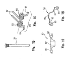
- the torsion springs of the biasing members 28 have their coiled portions 50 mounted on the pivot pins 24, with one end 51 of each spring engaging a part of one of the front clamping members 23, and the other end 52 of each spring engaging a part of one of the rear clamping members 25.
- the biasing members 28 normally urge clamping members 23 and 25 to rotate about their respective pivot pins 24 from their cleat releasing positions to their cleat engaging or clamping positions. In other words, the biasing members 28 normally maintain the clamping members 23 and 25 in their cleat engaging positions.
- the release forces of the biasing members 28 of the clamping members 23 and 25 are controlled by switching which of the cleats A and B are used with which of the pedals 12a and 12b.
- the clamping members 23 and 25 selectively engage one of the cleats A and B.
- the clamping members 23 and 25 are pivotally coupled to the ends of the pedal body 22 by the pivot pins 24.
- the clamping members 23 and 25 are curved in a roughly U-shaped configuration when view along the center longitudinal line CL of the pedal body 22, with their two free ends being swingably supported by the pivot pins 24 that pass between the inner and outer side mounting portions 42 and 43 of the pedal body 22.
- each of the front clamping members 23 includes a connecting portion 60 with a pair of legs 61 extending downwardly from connecting portion 60 for coupling the front clamping member 23 to the pedal body 22 via one of the pivot pins 24. More specifically, each of the legs 61 of the front clamping members 23 has a mounting hole 63 formed therein for receiving one of the pivot pins 24. Accordingly, each of the front clamping members 23 is pivotally mounted about its respective pivot pin 24 for movement between a cleat clamping or engaging position and a cleat releasing position.
- Each of the connecting portions 60 of the front clamping members 23 has a front cleat engagement portion or surface 64 and a front cleat stop portion or surface 65.
- the front cleat engagement surface 64 faces generally towards the center plane P1 of the pedal body 22, while the front cleat stop surface 65 is spaced forwardly from the center rotational axis R of the pedal spindle 21 by a first predetermined distance d1 measured parallel to the front cleat engagement surface 64 as seen in Figures 8 and 11 .
- the front cleat engagement surface 64 of each front clamping member 23 is configured and arranged to engage a front portion of the cleats A and B to limit movement of the cleats A an B away from the pedal body.
- the front cleat stop surface 65 of each front clamping member 23 is configured and arranged to engage a front portion of the cleats A and B to limit forward movement of the cleats A and B.
- the front cleat engagement surface 64 is a flat planar surface.
- the front cleat stop surface 65 is a flat planar surface that extends substantially perpendicular to the front cleat engagement surface 64.
- Each of the legs 61 of the front clamping members 23 also has a first stop portion or flange 66 and a second stop portion or flange 67.
- the first stop portions 66 of each of the front clamping members 23 are configured and arranged to engage the pedal body 22 to limit rotational movement of the front clamping member 23 in a first rotational direction about the respective one of the pivot pins 24.
- the second stop portions 67 of each of the front clamping members 23 are configured and arranged to engage the pedal body 22 to limit rotational movement of the front clamping member 23 in a second rotational direction about the respective one of the pivot pins 24. More specifically, the first stop portions 66 of each of the front clamping members 23 are normally biased against the pedal body 22 by the respective one of the biasing members 28.
- each of the front clamping members 23 are normally spaced from pedal body 22 by a predetermined amount.
- the front clamping members 23 can pivot about the pivot pins 24 against the urging forces of the biasing members 28 such that the front clamping members 23 can pivot in a generally forward direction by a first predetermined rotational distance or amount ⁇ 1.
- the front clamping members 23 can pivot in a generally forward direction by approximately three degrees to about five degrees as measured about the center axis of the respective one of the pivot pins 24.
- each of the rear clamping members 25 includes a connecting portion 70 with a pair of legs 71 extending downwardly from connecting portion 70 for coupling the rear clamping member 25 to the pedal body 22 via one of the pivot pins 24. More specifically, each of the legs 71 of the rear clamping members 25 has a mounting hole 73 formed therein for receiving one of the pivot pins 24. Accordingly, each of the rear clamping members 25 is pivotally mounted about its respective pivot pin 24 for movement between a cleat clamping or engaging position and a cleat releasing position.
- Each of the connecting portions 70 of the rear clamping members 25 has a rear cleat engagement portion or surface 74 and a rear cleat stop portion or surface 75.
- the rear cleat engagement surface 74 faces generally towards the center plane P1 of the pedal body 22.
- the rear cleat stop surface 75 is spaced rearwardly from the center rotational axis R of the pedal spindle 21 by a second predetermined distance d2 measured parallel to the rear cleat engagement surface 74 as seen in Figures 8 and 11 .
- the rear cleat engagement surface 74 of each rear clamping member 25 is configured and arranged to engage a rear portion of the cleats A and B to limit movement of the cleats A an B away from the pedal body.
- each rear clamping member 25 is configured and arranged to engage a rear portion of the cleats A and B to limit rearward movement of the cleats A and B.
- the rear cleat engagement surface 75 is a flat planar surface.
- the rear cleat stop surface 75 is a flat planar surface that extends substantially perpendicular to the rear cleat engagement surface 74.
- Each of the legs 71 of the rear clamping members 25 also has a stop surface 76 that is configured and arranged to engage the pedal body 22 to limit rotational movement of the rear clamping member 25 in a first rotational direction about the respective one of the pivot pins 24, i.e., hold the rear clamping member 25 in rest or cleat engaging position. More specifically, the stop surfaces 76 of each of the rear clamping members 25 are normally biased against the pedal body 22 by the respective one of the biasing members 28. Thus, the rear clamping members 25 can pivot about the pivot pins 24 against the urging forces of the biasing members 28 such that the rear clamping members 25 can pivot in a generally rearward direction by a predetermined rotational distance or amount ⁇ 2, as seen in Figure 6 .
- the predetermined rotational distance ⁇ 2 is about thirteen degrees, when the pedal and cleat are arranged to require the first predetermined outward twisting force F1 and about fourteen degrees, when the pedal and cleat are arranged to require the second predetermined outward twisting force F2.
- the rear clamping members 25 can pivot in a generally rearward direction by at least fourteen degrees as measured about the center axis of the respective one of the pivot pins 24.
- first and second cleat engagement surfaces 64 and 74 preferably lie in substantially the same plane, which forms an acute angle with the center plane P1.
- the first and second cleat engagement surfaces 64 and 74 hold the cleat A or B from moving vertically from the pedal body 22.
- the first cleat engagement surface 64 is spaced from the pivot axis of the pivot pin 24 by a predetermined distance L1
- the second cleat engagement surface 74 is spaced from the pivot axis of the pivot pin 24 by a predetermined distance L2 that is larger than the predetermined distance L1.
- the first and second cleat stop surfaces 65 and 75 hold the cleat A or B from moving in a front to rearward direction of the pedal body 22.
- the first and second cleat stop surfaces 65 and 75 are spaced apart by a predetermined distance S1. Moreover, the second cleat stop surface 75 is spaced (offset) from the center rotational axis R of the pedal spindle 21 by the predetermined distance d2, while the first cleat stop surface 65 is spaced (offset) from the center rotational axis R of the pedal spindle 21 by the predetermined distance d1 that is larger than the predetermined distance d2.
- the dimensions d1 and d2 are measured along a plane that extends perpendicular to the first and second cleat stop surfaces 65 and 75. Since dimension d1 is greater than the dimension d2, the step-in torque is approximately 17% greater than if the dimensions d1 and d2 were equal.
- the rear clamping members 25 are provided with a generally horizontal portion 77 and a generally vertical portion 78.
- the portions 77 and 78 form an elongated tongue having an L-shape as viewed from the side. This elongated tongue assists the rider in rotating the real body 22 to horizontal position for engagement as seen in Figures 39 and 40 .
- the generally horizontal portion 77 extends in a substantially rearward direction past the end of the pedal body 22 by a predetermined distance S2 that is at least substantially equal to or greater than the predetermined distance S1.
- the generally horizontal portion 77 of the rear clamping members 25 is provided with an opening 79 for receiving the spring holder 26 to couple the second ends 52 of the torsion springs that form the biasing member 28 to the rear clamping member 25.
- each of the pedal body covers 30 basically includes a protective body portion 90, a first attachment leg 91 and a second attachment leg 92.
- the first and second attachment legs 91 and 92 have attachment holes 93 and 94, respectively, for receiving the pivot pins 24 therethrough.
- the pedal body covers 30 are fixedly coupled to the pedal body 22 by the pivot pins 24.
- Each of the pedal body covers 30 is a rigid member that is preferably made as a one-piece, unitary member from a material that is harder than the material of the pedal body 22 such as stainless steel.
- the pedal body covers 30 are located at the ends of the center tubular portion 41 in the area where the cleat A or B will rub against the pedal body 22 if the pedal body covers 30 were removed.
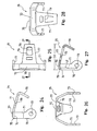
- the cleats A and B are basically mirror images of each other. It will be apparent to those skilled in the art from this disclosure that the descriptions of the portions of the cleat A ( Figures 29-33 ) also to applies to the corresponding portions of the cleat B ( Figures 34-38 ) and vice a versa. Thus, the same reference numerals will be used to describe both the portions of the cleat A and the corresponding portions of the cleat B for the sake of brevity.
- each of the cleats A and B includes an attachment portion 100, a first or front coupling portion or member 101 extending from one end of the attachment portion 100 and a second or rear coupling portion or member 102 extending from the other end of the attachment portion 100.
- the front coupling portion or member 101 has a pair of lateral front corner abutments C F1 and C F2
- the rear coupling portion or member 102 has a pair of lateral rear corner abutments C R1 and C R2 .
- the front corner abutments C F1 and C F2 selectively contact the front clamping member 23 when the cleat is pivoted about its pivot axis P of the cleat A or B, while the rear corner abutments C R1 and C R2 selectively contact the rear clamping member 25 when the cleat is pivoted about its pivot axis P of the cleat A or B.
- the pivot axis P is located at the intersection of a first line that extends between the front and rear corner abutments C F1 and C R1 and a second line that extends between the front and rear corner abutments C F2 and C R2 as seen in Figures 33 and 38 .
- the pivot axis P also lies on a center line CL of the cleat A or B.
- the front and rear corner abutments C F1 and C R1 are spaced laterally from the center line CL of the cleat A or B by a first lateral distance DL 1
- the front and rear corner abutments C F2 and C R2 are spaced laterally from the center line CL of the cleat A or B by a second lateral distance DL 2 that is larger than the first lateral distance DL 1 .
- This arrangement at least partially results in the low outward twisting force F1 and the high outward twisting force F2 for release the cleat A or B depending on which of the cleats A and B are used with which of the pedals 12a and 12b.
- the attachment portion 100 has an upper sole side 103 facing in a first direction for engaging the sole of the shoe and a lower pedal side facing 104 in a second direction which is substantially opposite to the first direction.
- the attachment portion 100 and the coupling portions 101 and 102 are integrally formed together as a one-piece, unitary member, which is constructed from a suitable rigid material.
- the attachment portion 100 has a pair of hole or slot 105 for receiving one or more fasteners for fixedly coupling to the sole of the cyclist's shoe in a relatively conventional manner.
- the interconnection of the cleat A to the sole is relatively well known in the art, and thus, this interconnection will not be discussed or illustrated in detail herein.
- the front coupling portion 101 is designed to engage the front clamping member 23.
- the front coupling portion 101 has a nose portion or flange 106 with a first or front coupling surface 106a, a center front stop surface 107 and a pair of lateral front stop surfaces 108.
- the front coupling surface 106a faces towards the sole of the shoe, while the front stop surfaces 107 and 108 extend substantially perpendicular to the front coupling surface 106a.
- the center front stop surface 107 is designed to engage the front stop surface 65 of the front clamping member 23 to prevent forward movement of the cleats relative to the pedal body 22.
- the center front stop surfaces 107 is arranged to extend perpendicular to a center line CL of the cleat A or B that divides the front coupling surface 106a into two equal side portions.
- the lateral front stop surfaces 108 are angled relative to the center front stop surfaces 107 so that they are inclined rearwardly as they extend outwardly from the center front stop surfaces 107.
- the lateral front stop surfaces 108 are angled about five degrees relative to the center front stop surfaces 107.
- the lateral front stop surfaces 108 are designed to engage the front stop surface 65 of the front clamping member 23 when the cleat is pivoted about its pivot axis P of the cleat A or B.
- the lateral front stop surfaces 108 form the front lateral corner abutments C F1 and C F2 that are spaced from the center line CL of the cleat A or B.
- the front lateral corner abutment C F1 is spaced a shorter distance from the center line CL of the cleat A or B than the front lateral corner abutment C R2 from the center line CL of the cleat A or B.
- the rear lateral corner abutment C R1 forms a low force rear corner abutment
- the rear lateral corner abutment C R2 forms a high force rear corner abutment.
- the second or rear coupling portion 102 extends from the second end of the attachment portion 100.
- the rear coupling portion 102 is designed to engage the rear clamping member 25.
- the rear coupling portion 102 has a nose portion or rear flange 109 and a center rear stop surface 110 and a pair of lateral rear stop surfaces 111.
- the nose portion or rear flange 109 includes a second or rear coupling surface 109a and a rear edge 109b extending perpendicularly relative to the rear coupling surface 109a.
- the rear edge 109b includes corners C RR1 and C RR2 that define the release points of the rear flange 109.
- the rear flange 109 will be twisted outwardly from underneath the rear clamping member 25.
- the cleat A or B will release from the rear clamping member 25 when one of the corners C RR1 and C RR2 of the rear flange 109 aligns with the rear stop surface 75 of the rear clamping member 25.
- the rear flange of the cleat A or B releases from the rear stop surface 75 of the rear clamping member 25.
- the corner C RR1 is located on the same side of the center line CL as the rear lateral corner abutment C R1
- the corner C RR2 is located on the same side of the center line CL as the rear lateral corner abutment C R2
- the rear flange 109 is shifted from the center line CL towards the rear lateral corner abutment C R2 by an OFFSET distance to control the release angle.
- the corners C RR1 and C RR2 of the rear flange 109 are symmetrically arranged about the OFFSET axis that is parallel to the center line CL.
- the OFFSET distance is about 0.65 mm from the center line CL of the cleat A or B towards the rear lateral corner abutment C R2 .
- this OFFSET distance is dimensioned together with the corners C RR1 and C RR2 of the rear flange 109 and the rear lateral corner abutments C R1 and C R2 such that the release angle (e.g., 15°) is substantially identical for each of the cleats A and B whether used with the left pedal 12a or the right pedal 12b.
- the rear coupling surface 109a faces towards the sole of the shoe, while the rear stop surfaces 110 and 111 extend substantially perpendicular to the rear coupling surface 110.
- the rear stop surfaces 110 and 111 are designed to engage the stop surface 75 of the rear clamping member 25 to prevent rearward movement of the cleat A or B relative to the pedal body 22.
- the coupling surfaces 106a and 109a are formed so as to lie in substantially the same plane.
- the lateral rear stop surfaces 111 are angled relative to the center rear stop surface 110 so that they are inclined forwardly as they extend outwardly from the center rear stop surface 110. Preferably, the lateral rear stop surfaces 111 are angled about five degrees relative to the center rear stop surface 110.
- the lateral rear stop surfaces 111 are designed to engage the rear stop surface 75 of the rear clamping member 25 when the cleat A or B is pivoted about its pivot axis P of the cleat A or B.
- the rear stop surfaces 110 and 111 are symmetrically arranged about an OFFSET that is spaced by 0.65 mm to one side of the cleat A or B from the center line CL of the cleat A or B.
- the lateral rear stop surfaces 111 form the rear lateral corner abutments C R1 and C R2 that are spaced from the center line CL of the cleat A or B.
- the rear lateral corner abutments C R1 and C R2 form effective lever arms 112 and 113, respectively, i.e., the length from pivot axis P of the cleat A or B to the lateral corner abutments C R1 and C R2 .
- the lever arm 112 is shorter than the lever arm 113.
- the lateral corner abutment C R1 is spaced a shorter distance from the center line CL of the cleat A or B than the lateral corner abutment C R2 from the center line CL of the cleat A or B.
- the cleat A or B easier to pivot to the release position than the lateral corner abutment C R2 engages the rear stop surface 75 of the rear clamping member 25.
- the bicycle pedals 12a and 12b are assembled by initially installing the front and rear clamping members 23 and 25 to the bicycle pedal body 22 by the pivot pins 24. This is done by positioning the front and rear clamping members 23 and 25 between the side mounting portions 42 and 43.
- the four pedal body covers 30 are mounted in the cover receiving recesses 45.
- first and second attachment legs 91 and 92 of the four pedal body covers 30 have their attachment holes 93 and 94 arranged for receiving the pivot pins 24 therethrough.
- the biasing members 28 are held in place between the front and rear clamping members 23 and 25.
- the pivot pins 24 are now installed in the pedal body 22 such that the front and rear clamping members 23 and 25, the biasing members 28 and the pedal body covers 30 are mounted on the pivot pins 24.
- the pedal body covers 30 are fixedly coupled to the pedal body 22 by the pivot pins 24, while the front and rear clamping members 23 and 25 are pivotally coupled to the pedal body 22 by the pivot pins 24.
- the biasing members 28 are not in their fully preloaded state.
- the springs of the biasing members 28 are now wound about the pivot pins 24 and the spring holders 26 are insert into openings of the rear clamping members 25 to properly preload the biasing members 28, which urge the front and rear clamping members 23 and 25 to their rest positions.
- biasing members 28 to be initially installed in unload or load loaded state for easy assembly.
- the front and rear clamping members 23 and 25 and the biasing members 28 can be installed on the bicycle pedal body 22 without having to preloaded the biasing members 28 under high tension.
- the rider can easily rotate the pedal 12a. Moreover, when the pedal 12a is in the non-horizontal position shown in Figure 40 , the rider can easily rotate the pedal 12a in either direction.
- the front end of the cleat A or B rotates the front clamping member 25 forward against the biasing force of the other one of the biasing members 28.
- the cleat A or B then slides between the front and rear clamping member 23 and 25.
- the front and rear clamping member 23 and 25 are biased by the biasing members 28 back to their original positions.
- the cleat A or B is engaged between the front and rear clamping member 23 and 25 (see Figure 2 ).
- the following directional terms "forward, rearward, above, downward, vertical, horizontal, below and transverse” as well as any other similar directional terms refer to those directions of a bicycle equipped with a pedal of the present invention and when the pedal is horizontally oriented relative to the ground. Accordingly, these terms, as utilized to describe the present invention should be interpreted relative to a bicycle equipped with a pedal of the present invention.
Landscapes
- Engineering & Computer Science (AREA)
- Chemical & Material Sciences (AREA)
- Combustion & Propulsion (AREA)
- Transportation (AREA)
- Mechanical Engineering (AREA)
- Footwear And Its Accessory, Manufacturing Method And Apparatuses (AREA)
- Mechanical Control Devices (AREA)
Claims (24)
- Fahrradpedalbaugruppe, aufweisend:ein Fahrradpedal (12a, 12b) beinhaltendeine Pedalachse (21), die eine Rotationsmittelachse aufweist; einen Pedalkörper (22), der mit der Pedalachse (21) um die Rotationsmittelachse der Pedalachse (21) drehbar verbunden ist, wobei der Pedalkörper (22) ein erstes Ende und ein zweites Ende aufweist, wobei sich eine Mittelebene zwischen den ersten und zweiten Enden erstreckt und durch die Rotationsmittelachse der Pedalachse (21) verläuft;ein vorderes Einspannelement (23), das mit dem ersten Ende des Pedalkörpers (22) verbunden ist, wobei das vordere Einspannelement (23) eine vordere Stolleneingreiffläche aufweist, die zur Mittelebene des Pedalkörpers (22) gewandt ist; undein hinteres Einspannelement (25), das mit dem zweiten Ende des Pedalkörpers (22) verbunden ist, wobei das hintere Einspannelement (25) eine hintere Stolleneingreiffläche aufweist, die zur Mittelebene des Pedalkörpers (22) gewandt ist; dadurch gekennzeichnet, dassein erster Fahrradschuhstollen (A) erste vordere und hintere Befestigungsabschnitte beinhaltet, die konfiguriert und angeordnet sind, um mit den vorderen und hinteren Einspannelementen (23, 25) zusammenzuarbeiten, um den ersten Fahrradschuhstollen (A) aus einer Stolleneingreifposition in eine Stollenfreigabeposition freizugeben, und zwar bei Aufbringen einer ersten vorbestimmten Größe einer nach außen gerichteten Verdrehkraft; undeinen zweiten Fahrradschuhstollen (B), der zweite vordere und hintere Befestigungsabschnitte beinhaltet, die konfiguriert und angeordnet sind, um mit den vorderen und hinteren Einspannelementen (23, 25) zusammenzuarbeiten, um den zweiten Fahrradschuhstollen (B) aus der Stolleneingreifposition in die Stollenfreigabeposition freizugeben, und zwar bei Aufbringen einer zweiten vorbestimmten Größe einer nach außen gerichteten Verdrehkraft, die größer als die erste vorbestimmte Größe einer nach außen gerichteten Verdrehkraft ist;wobei die ersten und zweiten Fahrradschuhstollen (A, B) weiter konfiguriert und angeordnet sind, um sich vom Fahrradpedal (12a, 12b) bei einem im Wesentlichen identischen Stollenfreigabewinkel zu lösen.
- Fahrradpedalbaugruppe nach Anspruch 1, bei der
das hintere Einspannelement (25) mit dem Pedalkörper (22) beweglich verbunden ist, um sich zwischen der Stolleneingreifposition und der Stollenfreigabeposition zu bewegen. - Fahrradpedalbaugruppe nach Anspruch 1 oder 2, bei der
die ersten und zweiten Fahrradschuhstollen (A, B) konfiguriert und angeordnet sind, um das hintere Einspannelement (25) um ein gleich großes Ausmaß auszulenken. - Fahrradpedalbaugruppe nach Anspruch 1 oder 2, bei der
die ersten und zweiten Fahrradschuhstollen (A, B) derart konfiguriert und angeordnet sind, dass der zweite Fahrradschuhstollen (B) das hintere Einspannelement (25) geringfügig mehr als der erste Fahrradschuhstollen (A) auslenkt. - Fahrradpedalbaugruppe nach Anspruch 4, bei der
das hintere Einspannelement (25) mit dem Pedalkörper (22) um eine hintere Schwenkachse schwenkbar verbunden ist, wobei ein Vorspannelement (28) das hintere Einspannelement (25) zur Stolleneingreifposition hin vorspannt. - Fahrradpedalbaugruppe nach einem der vorhergehenden Ansprüche, bei der
der erste vordere Befestigungsabschnitt eine erste vordere Verbindungsfläche beinhaltet, die wahlweise mit der vorderen Eingreiffläche des vorderen Einspannelementes (23) in Eingriff gebracht werden kann, der erste hintere Befestigungsabschnitt eine erste hintere Verbindungsfläche beinhaltet, die mit der hinteren Eingreiffläche des hinteren Einspannelementes (25) wahlweise in Eingriff gebracht werden kann; und
der zweite vordere Befestigungsabschnitt eine zweite vordere Verbindungsfläche beinhaltet, die wahlweise mit der vorderen Eingreiffläche des vorderen Einspannelementes (23) in Eingriff gebracht werden kann, der zweite hintere Befestigungsabschnitt eine zweite hintere Verbindungsfläche beinhaltet, die mit der hinteren Eingreiffläche des hinteren Einspannelementes (25) wahlweise in Eingriff gebracht werden kann. - Fahrradpedalbaugruppe nach Anspruch 6, bei der
die ersten vorderen und hinteren Befestigungsabschnitte des ersten Fahrradschuhstollens (A) im Wesentlichen Spiegelbilder der zweiten vorderen und hinteren Befestigungsabschnitte des zweiten Fahrradschuhstollens (B) sind. - Fahrradpedalbaugruppe nach Anspruch 6 oder 7, bei der
der erste hintere Befestigungsabschnitt weiter eine eine hohe Freigabekraft aufweisende Eingreiffläche aufweist, die auf einer ersten Seite einer von vorne nach hinten verlaufenden Längsmittelachse des ersten Fahrradschuhstollens (A) angeordnet und konfiguriert ist, um mit einem Innenseiten-Teilstück des hinteren Einspannelementes (25) wahlweise in Eingriff zu kommen und das hintere Einspannelement (25) bei Aufbringen der ersten vorbestimmten Größe einer nach außen wirkenden Verdrehkraft auf den ersten Fahrradschuhstollen (A) relativ zum Pedalkörper (22) zu bewegen, und
der zweite hintere Befestigungsabschnitt weiter eine eine geringe Freigabekraft aufweisende Eingreiffläche beinhaltet, die auf einer ersten Seite einer von vorne nach hinten verlaufenden Längsmittelachse des zweiten Fahrradschuhstollens (B) angeordnet und konfiguriert ist, um mit dem Innenseiten-Teilstück des hinteren Einspannelementes (25) wahlweise in Eingriff zu kommen und das hintere Einspannelement (25) bei Aufbringen der zweiten vorbestimmten Größe einer nach außen wirkenden Verdrehkraft auf den zweiten Fahrradschuhstollen (B) relativ zum Pedalkörper (22) zu bewegen. - Fahrradpedalbaugruppe nach Anspruch 1, aufweisend:rechte und linke Fahrradpedale (12a, 12b), wobei jedes der rechten und linken Fahrradpedale (12a, 12b) beinhaltet:eine Pedalachse (21), die eine Rotationsmittelachse aufweist; einen Pedalkörper (22), der mit der Pedalachse (21) um die Rotationsmittelachse der Pedalachse (21) drehbar verbunden ist, wobei der Pedalkörper (22) ein erstes Ende und ein zweites Ende aufweist, wobei sich eine Mittelebene zwischen den ersten und zweiten Enden erstreckt und durch die Rotationsmittelachse der Pedalachse (21) verläuft;ein vorderes Einspannelement (23), das mit dem ersten Ende des Pedalkörpers (22) verbunden ist, wobei das vordere Einspannelement (23) eine vordere Stolleneingreiffläche aufweist, die zur Mittelebene des Pedalkörpers (22) gewandt ist; undein hinteres Einspannelement (25), das mit dem zweiten Ende des Pedalkörpers (22) verbunden ist, wobei das hintere Einspannelement (25) eine hintere Stolleneingreiffläche aufweist, die zur Mittelebene des Pedalkörpers (22) gewandt ist;einen ersten Fahrradschuhstollen (A), der erste vordere und hintere Befestigungsabschnitte beinhaltet, die konfiguriert und angeordnet sind, um wahlweise mit den vorderen und hinteren Einspannelementen (23, 25) der rechten und linken Fahrradpedale (12a, 12b) zusammenzuarbeiten; undeinen zweiten Fahrradschuhstollen (B), der zweite vordere und hintere Befestigungsabschnitte beinhaltet, die konfiguriert und angeordnet sind, um wahlweise mit den vorderen und hinteren Einspannelementen (23, 25) der rechten und linken Fahrradpedale (12a, 12b) zusammenzuarbeiten,wobei der erste Fahrradschuhstollen (A) weiter konfiguriert und angeordnet ist, um sich vom linken Fahrradpedal (12b) zu lösen, und zwar bei Aufbringen einer ersten vorbestimmten Größe einer nach außen gerichteten Verdrehkraft auf den ersten Fahrradschuhstollen (A),der zweite Fahrradschuhstollen (B) weiter konfiguriert und angeordnet ist, um sich vom rechten Fahrradpedal (12a) zu lösen, und zwar bei Aufbringen der ersten vorbestimmten Größe einer nach außen gerichteten Verdrehkraft auf den zweiten Fahrradschuhstollen (B),wobei der erste Fahrradschuhstollen (A) weiter konfiguriert und angeordnet ist, um sich vom rechten Fahrradpedal (12a) zu lösen, und zwar bei Aufbringen einer zweiten vorbestimmten Größe einer nach außen gerichteten Verdrehkraft, die größer als die erste vorbestimmte Größe einer nach außen gerichteten Verdrehkraft ist, auf den ersten Fahrradschuhstollen (A),der zweite Fahrradschuhstollen (B) weiter konfiguriert und angeordnet ist, um sich vom linken Fahrradpedal (12b) zu lösen, und zwar bei Aufbringen der zweiten vorbestimmten Größe einer nach außen gerichteten Verdrehkraft auf den zweiten Fahrradschuhstollen (B).
- Fahrradpedalbaugruppe nach Anspruch 9 und einem der Ansprüche 2 bis 8, wobei die ersten und zweiten Fahrradschuhstollen (A, B) konfiguriert und angeordnet sind, um sich von den rechten und linken Fahrradpedalen (12a, 12b) bei einem im Wesentlichen identischen Stollenfreigabewinkel zu lösen.
- Fahrradpedalbaugruppe nach Anspruch 9 oder 10, bei der
das hintere Einspannelement (25) des rechten Fahrradpedals (12a) mit dem Pedalkörper (22) des rechten Fahrradpedals (12a) beweglich verbunden ist, um sich zwischen einer Stolleneingreifposition und einer Stollenfreigabeposition zu bewegen, und
das hintere Einspannelement (25) des linken Fahrradpedals (12b) mit dem Pedalkörper (22) des linken Fahrradpedals (12b) beweglich verbunden ist, um sich zwischen einer Stolleneingreifposition und einer Stollenfreigabeposition zu bewegen. - Fahrradpedalbaugruppe nach Anspruch 9, bei der
die ersten und zweiten Fahrradschuhstollen (A, B) und die hinteren Einspannelemente (23, 25) der linken und rechten Fahrradpedale (12a, 12b) konfiguriert und angeordnet sind, um die hinteren Einspannelemente (25) der rechten und linken Fahrradpedale (12a, 12b) um ein gleich großes Ausmaß auszulenken, ungeachtet dessen, welche von den ersten und zweiten Fahrradschuhstollen (A, B) mit den linken und rechten Fahrradpedalen (12a, 12b) verwendet werden. - Fahrradpedalbaugruppe nach Anspruch 9, bei der
der erste Fahrradschuhstollen (A) und das hintere Einspannelement (25) des linken Fahrradpedals (12b) weiter derart konfiguriert und angeordnet sind, dass das hintere Einspannelement (25) des linken Fahrradpedals (12b) um ein erstes Auslenkausmaß ausgelenkt wird, um den ersten Fahrradschuhstollen (A) aus dem linken Fahrradpedal (12b) freizugeben, und zwar bei Aufbringen der ersten vorbestimmten Größe einer nach außen gerichteten Verdrehkraft auf den ersten Fahrradschuhstollen (A),
der zweite Fahrradschuhstollen (B) und das hintere Einspannelement (25) des rechten Fahrradpedals (12a) weiter derart konfiguriert und angeordnet sind, dass das hintere Einspannelement (25) des rechten Fahrradpedals (12a) um ein erstes Auslenkausmaß ausgelenkt wird, um den ersten Fahrradschuhstollen (A) aus dem rechten Fahrradpedal (12a) freizugeben, und zwar bei Aufbringen der ersten vorbestimmten Größe einer nach außen gerichteten Verdrehkraft auf den ersten Fahrradschuhstollen (A),
der erste Fahrradschuhstollen (A) und das hintere Einspannelement (25) des rechten Fahrradpedals (12a) weiter derart konfiguriert und angeordnet sind, dass das hintere Einspannelement (25) des rechten Fahrradpedals (12a) um ein zweites Auslenkausmaß ausgelenkt wird, das geringfügig größer als das erste Auslenkausmaß ist, um den ersten Fahrradschuhstollen (A) aus dem rechten Fahrradpedal (12a) freizugeben, und zwar bei Aufbringen der zweiten vorbestimmten Größe einer nach außen gerichteten Verdrehkraft auf den ersten Fahrradschuhstollen (A), und
der zweite Fahrradschuhstollen (B) und das hintere Einspannelement (25) des linken Fahrradpedals (12b) weiter derart konfiguriert und angeordnet sind, dass das hintere Einspannelement (25) des linken Fahrradpedals (12b) um das zweite Auslenkausmaß ausgelenkt wird, um den zweiten Fahrradschuhstollen (B) aus dem linken Fahrradpedal (12b) freizugeben, und zwar bei Aufbringen der zweiten vorbestimmten Größe einer nach außen gerichteten Verdrehkraft auf den zweiten Fahrradschuhstollen (B). - Fahrradpedalbaugruppe nach Anspruch 13, bei der
das hintere Einspannelement (25) des rechten Fahrradpedals (12a) mit dem Pedalkörper (22) des rechten Fahrradpedals (12a) um eine hintere Schwenkachse schwenkbar verbunden ist, wobei ein Vorspannelement (28) das hintere Einspannelement (25) des rechten Fahrradpedal (12a) in eine Stolleneingreifposition vorspannt, und
das hintere Einspannelement (25) des linken Fahrradpedals (12a) mit dem Pedalkörper (22) des linken Fahrradpedals (12b) um eine hintere Schwenkachse schwenkbar verbunden ist, wobei ein Vorspannelement (28) das hintere Einspannelement (25) des linken Fahrradpedals (12b) in eine Stolleneingreifposition vorspannt. - Fahrradpedalbaugruppe nach Anspruch 9 oder 10, bei der
der erste hintere Befestigungsabschnitt des ersten Fahrradschuhstollens (A) weiter eine erste eine geringe Freigabekraft aufweisende Eingreiffläche, die auf einer ersten Seite einer von vorne nach hinten verlaufenden Längsmittelachse des ersten Fahrradschuhstollens (A) angeordnet ist, und eine erste eine hohe Freigabekraft aufweisende Eingreiffläche beinhaltet, die auf einer zweiten Seite einer von vorne nach hinten verlaufenden Längsmittelachse des ersten Fahrradschuhstollens (A) angeordnet ist,
wobei die erste eine geringe Freigabekraft aufweisende Eingreiffläche konfiguriert ist, um wahlweise mit einem Innenseiten-Teilstück des hinteren Einspannelementes (25) des linken Fahrradpedals (12b) in Eingriff zu kommen und das hintere Einspannelement (25) des linken Fahrradpedals (12b), bei Aufbringen der ersten vorbestimmten Größe einer nach außen wirkenden Verdrehkraft auf den ersten Fahrradschuhstollen (A), relativ zum linken Fahrradpedal (12b) zu bewegen,
wobei die erste eine hohe Freigabekraft aufweisende Eingreiffläche konfiguriert ist, um wahlweise mit einem Innenseiten-Teilstück des hinteren Einspannelementes (25) des rechten Fahrradpedals (12a) in Eingriff zu kommen und das hintere Einspannelement (25) des rechten Fahrradpedals (12a), bei Aufbringen der zweiten vorbestimmten Größe einer nach außen wirkenden Verdrehkraft auf den ersten Fahrradschuhstollen (A), relativ zum rechten Fahrradpedal (12a) zu bewegen,
der erste hintere Befestigungsabschnitt des zweiten Fahrradschuhstollens (B) weiter eine zweite eine geringe Freigabekraft aufweisende Eingreiffläche, die auf einer ersten Seite einer von vorne nach hinten verlaufenden Längsmittelachse des zweiten Fahrradschuhstollens (B) angeordnet ist, und eine zweite eine hohe Freigabekraft aufweisende Eingreiffläche beinhaltet, die auf einer zweiten Seite einer von vorne nach hinten verlaufenden Längsmittelachse des zweiten Fahrradschuhstollens (B) angeordnet ist,
wobei die zweite eine geringe Freigabekraft aufweisende Eingreiffläche konfiguriert ist, um wahlweise mit einem Innenseiten-Teilstück des hinteren Einspannelementes (25) des rechten Fahrradpedals (12a) in Eingriff zu kommen und das hintere Einspannelement (25) des rechten Fahrradpedals (12a), bei Aufbringen der ersten vorbestimmten Größe einer nach außen wirkenden Verdrehkraft auf den zweiten Fahrradschuhstollen (B), relativ zum rechten Fahrradpedal (12a) zu bewegen,
wobei die zweite eine hohe Freigabekraft aufweisende Eingreiffläche konfiguriert ist, um wahlweise mit einem Innenseiten-Teilstück des hinteren Einspannelementes (25) des linken Fahrradpedals (12b) in Eingriff zu kommen und das hintere Einspannelement (25) des linken Fahrradpedals (12b), bei Aufbringen der zweiten vorbestimmten Größe einer nach außen wirkenden Verdrehkraft auf den zweiten Fahrradschuhstollen (B), relativ zum linken Fahrradpedal (12b) zu bewegen. - Fahrradpedalbaugruppe nach einem der vorhergehenden Ansprüche, wobei die ersten und zweiten Fahrradschuhstollen (A, B) aufweisen:einen Befestigungsabschnitt (100), der ein vorderes Ende, ein hinteres Ende, eine obere Sohlenseite, die in eine erste Richtung gewandt ist, und eine untere Pedalseite aufweist, die in eine zweiten Richtung gewandt ist, die im Wesentlichen entgegengesetzt zur ersten Richtung ist;einen vorderen Verbindungsabschnitt (101), der sich vom vorderen Ende erstreckt, wobei der vordere Verbindungsabschnitt (101) eine vordere Verbindungsfläche aufweist, die in der ersten Richtung weist, und eine vordere Anschlagfläche aufweist, die in Richtung nach vorne weist; undeinen hinteren Verbindungsabschnitt (102), der sich vom hinteren Ende erstreckt, wobei der hintere Verbindungsabschnitt (102) eine hintere Verbindungsfläche (109a), die in der ersten Richtung weist, und eine hintere Anschlagfläche (75) aufweist, die in Richtung nach hinten weist, wobei ein für eine geringe Kraft dienendes hinteres Eckwiderlager an einem seitlichen Ende der hinteren Anschlagfläche (75) ausgebildet ist, und ein für eine hohe Kraft dienendes hinteres Eckwiderlager am anderen seitlichen Ende der hinteren Anschlagfläche (75) ausgebildet ist,die vorderen und hinteren Verbindungsabschnitte (101, 102) konfiguriert sind, um eine Schwenkachse des Stollens zu definieren, wobei das für eine höhere Kraft dienende hintere Eckwiderlager weiter von einer Mittellinie des Stollens beabstandet ist, welche die Schwenkachse des Stollens beinhaltet, als das für eine niedrige Kraft dienende hintere Eckwiderlager.
- Fahrradpedalbaugruppe nach Anspruch 16, bei der
die hintere Anschlagfläche (75) ein Paar von seitlichen hinteren Anschlagflächen (111) beinhaltet, die relativ zur Mittellinie des Stollens nach vorne abgewinkelt sind, während sich die seitlichen hinteren Anschlagflächen (111) von der Mittellinie des Stollens nach außen erstrecken. - Fahrradpedalbaugruppe nach Anspruch 16, bei der
die vordere Anschlagfläche (75) ein Paar von seitlichen vorderen Anschlagflächen beinhaltet, die relativ zur Mittellinie des Stollens nach vorne abgewinkelt sind, während sich die seitlichen vorderen Anschlagflächen von der Mittellinie des Stollens nach außen erstrecken. - Fahrradpedalbaugruppe nach Anspruch 16, bei der
der vordere Verbindungsabschnitt (101) ein für eine niedrige Kraft dienendes vorderes Eckwiderlager, das an einem seitlichen Ende der vorderen Anschlagfläche ausgebildet ist, und
ein für eine hohe Kraft dienendes vorderes Eckwiderlager beinhaltet, das am anderen seitlichen Ende der vorderen Anschlagfläche ausgebildet ist, die sich seitlich von der vorderen Verbindungsfläche (106a) befindet,
wobei das für eine niedrige Kraft dienende vordere Eckwiderlager diagonal relativ zu dem für eine niedrige Kraft dienenden hinteren Eckwiderlager angeordnet ist, und das für eine hohe Kraft dienende vordere Eckwiderlager diagonal bezüglich dem für eine hohe Kraft dienenden hinteren Eckwiderlager angeordnet ist. - Fahrradpedalbaugruppe nach Anspruch 19, bei der
das für eine hohe Kraft dienende vordere Eckwiderlager weiter von der Mittellinie des Stollens beabstandet angeordnet ist als das für eine niedrige Kraft dienende vordere Eckwiderlager. - Fahrradpedalbaugruppe nach Anspruch 19, bei der
die Schwenkachse des Stollens (A, B) durch die Kreuzungsstelle einer ersten diagonalen Linie, die sich durch das für eine niedrige Kraft dienende vordere Eckwiderlager hindurch und das für eine niedrige Kraft dienende hintere Eckwiderlager hindurch erstreckt, und einer zweiten diagonalen Linie definiert ist, die sich durch das für eine hohe Kraft dienende vordere Eckwiderlager und das für die hohe Kraft dienende hintere Eckwiderlager hindurch erstreckt. - Fahrradpedalbaugruppe nach Anspruch 16, bei der
der hintere Verbindungsabschnitt (102) einen hinteren Flansch beinhaltet, der sich vom hinteren Ende des Stollens (A, B) erstreckt, wobei der hintere Flansch von der Mittellinie des Stollens (A, B) zu dem für eine hohe Kraft dienenden hinteren Eckwiderlager versetzt ist. - Fahrradpedalbaugruppe nach Anspruch 22, bei der
der hintere Flansch (109) eine hintere Kante beinhaltet, deren erste Ecke sich zwischen der Mittellinie des Stollens (A, B) und dem für eine niedrige Kraft dienenden hinteren Eckwiderlager befindet und deren zweite Ecke sich zwischen der Mittellinie des Stollens (A, B) und dem für eine hohe Kraft dienenden hinteren Eckwiderlager befindet. - Fahrradpedalbaugruppe nach Anspruch 23, bei der
die zweite Ecke weiter von der Mittellinie des Stollens (A, B) beabstandet angeordnet ist als die erste Ecke.
Applications Claiming Priority (2)
| Application Number | Priority Date | Filing Date | Title |
|---|---|---|---|
| US712256 | 1991-06-07 | ||
| US10/712,256 US7013755B2 (en) | 2003-11-14 | 2003-11-14 | Bicycle pedal assembly |
Publications (3)
| Publication Number | Publication Date |
|---|---|
| EP1531120A2 EP1531120A2 (de) | 2005-05-18 |
| EP1531120A3 EP1531120A3 (de) | 2006-08-23 |
| EP1531120B1 true EP1531120B1 (de) | 2008-12-31 |
Family
ID=34435665
Family Applications (1)
| Application Number | Title | Priority Date | Filing Date |
|---|---|---|---|
| EP04021353A Expired - Lifetime EP1531120B1 (de) | 2003-11-14 | 2004-09-08 | Pedalvorrichtung für Fahrräder |
Country Status (6)
| Country | Link |
|---|---|
| US (4) | US7013755B2 (de) |
| EP (1) | EP1531120B1 (de) |
| JP (1) | JP2005145437A (de) |
| CN (1) | CN100344501C (de) |
| DE (1) | DE602004018727D1 (de) |
| TW (1) | TWI238801B (de) |
Families Citing this family (14)
| Publication number | Priority date | Publication date | Assignee | Title |
|---|---|---|---|---|
| US7013755B2 (en) * | 2003-11-14 | 2006-03-21 | Shimano Inc. | Bicycle pedal assembly |
| US20060248965A1 (en) * | 2005-05-06 | 2006-11-09 | Wyatt Roland J | Systems and methods of power output measurement |
| US8467979B2 (en) * | 2009-10-08 | 2013-06-18 | Alluvial Joules, Inc. | Intelligent sport shoe system |
| US8312791B2 (en) * | 2009-10-14 | 2012-11-20 | Shimano Inc. | Bicycle pedal |
| US9795184B2 (en) * | 2009-12-14 | 2017-10-24 | Shimano Inc. | Shoe positioning plate for bicycle shoes |
| DE202011000814U1 (de) | 2011-04-06 | 2011-11-08 | Chin-Long Hsieh | Modulartige Einrastvorrichtung eines rastbaren Pedals und rastbares Pedal mit dieser Einrastvorrichtung |
| JP5389110B2 (ja) * | 2011-07-29 | 2014-01-15 | 株式会社シマノ | 自転車用ペダル |
| US9090309B2 (en) * | 2011-09-28 | 2015-07-28 | Paul Swift | Spring-loaded retention and release mechanism for use on clipless bicycle pedals |
| ITMI20121483A1 (it) * | 2012-09-05 | 2014-03-06 | Angelo Morelli | Pedale automatico per biciclette |
| US9415832B2 (en) * | 2014-07-10 | 2016-08-16 | Shimano Inc. | Bicycle pedal |
| WO2016025966A1 (de) * | 2014-08-18 | 2016-02-25 | Michael Scheit | Fahrradpedalclip-abeckungs- und -auslösemechanismus |
| EP3538425B1 (de) | 2016-11-10 | 2026-04-08 | K88 Ehf. | Plattformadapter für cliploses fahrradpedal |
| WO2021247876A1 (en) | 2020-06-03 | 2021-12-09 | Milwaukee Electric Tool Corporation | Rivet setting tool |
| CN223507129U (zh) | 2022-07-08 | 2025-11-04 | 米沃奇电动工具公司 | 动力式紧固件驱动器 |
Family Cites Families (32)
| Publication number | Priority date | Publication date | Assignee | Title |
|---|---|---|---|---|
| US2202187A (en) * | 1938-01-24 | 1940-05-28 | May Marcus Chalette | Exerciser |
| US3960027A (en) * | 1975-10-08 | 1976-06-01 | Magnuson Leo D | Bicycle pedal attachment |
| ES2025100B3 (es) * | 1987-07-06 | 1992-03-16 | Look Sa | Zapato de ciclista |
| JPH01164693A (ja) * | 1987-09-10 | 1989-06-28 | Shimano Ind Co Ltd | 自転車用ペタル |
| JPH02128987A (ja) * | 1988-11-09 | 1990-05-17 | Shimano Ind Co Ltd | 自転車用ペダル |
| US5142938A (en) * | 1989-08-25 | 1992-09-01 | Sampson Sports, Inc. | Bicycle cleat and pedal with adjustable floating relationship |
| FR2653089B1 (fr) * | 1989-10-16 | 1994-04-08 | Jean Beyl | Dispositif de fixation d'une chaussure sur une pedale de bicyclette ou d'engin analogue, pedale de bicyclette, cale et semelle de chaussure pour un tel dispositif. |
| DE69018196T2 (de) * | 1989-11-14 | 1995-09-14 | Shimano Kk | Verbindungsstruktur zwischen Fahrradpedal und Stossplatte, Fahrradpedal und Stossplatte. |
| JPH0471980A (ja) * | 1990-07-09 | 1992-03-06 | Shimano Inc | 自転車用ペダル |
| JPH04183694A (ja) | 1990-11-13 | 1992-06-30 | Shimano Inc | 自転車用ペダル |
| NO172974C (no) * | 1991-08-16 | 1993-10-06 | Rune Angeltun | Sykkelpedal |
| GB2266687B (en) * | 1992-04-30 | 1995-06-14 | Chen Chung I | Quick-release clipless pedal |
| IT1257143B (it) * | 1992-11-04 | 1996-01-05 | Antonio Romano | Pedale di sicurezza per biciclette e simili. |
| TW262444B (de) * | 1993-04-08 | 1995-11-11 | Marui Kk | |
| US5685202A (en) * | 1996-02-05 | 1997-11-11 | Chen; Chung-I | Bicycle pedal device with two cleat retaining units |
| US5755144A (en) | 1996-08-26 | 1998-05-26 | Shimano, Inc. | Low profile bicycle pedal with top and bottom side clamping arrangements |
| US5868043A (en) * | 1997-06-28 | 1999-02-09 | Shimano, Inc. | Bicycle pedal |
| US6119551A (en) * | 1998-11-05 | 2000-09-19 | Shimano Inc. | Bicycle pedal and bicycle cleat |
| US6014914A (en) * | 1998-11-05 | 2000-01-18 | Shimano Inc. | Bicycle pedal |
| US6105462A (en) * | 1999-03-01 | 2000-08-22 | Shimano Inc. | Bicycle pedal |
| US6341540B2 (en) | 1999-04-06 | 2002-01-29 | John Douglas Steinberg | Clipless pedal |
| TW413212U (en) * | 1999-06-11 | 2000-11-21 | Chen Jung Yi | Suspending type foot pedal |
| US6230583B1 (en) | 1999-06-28 | 2001-05-15 | Shimano Inc. | Bicycle pedal |
| US6305244B1 (en) * | 1999-12-10 | 2001-10-23 | Shimano Inc. | Bicycle pedal |
| US6293169B1 (en) * | 1999-12-10 | 2001-09-25 | Shimano Inc. | Bicycle pedal |
| US6425304B1 (en) * | 2000-12-01 | 2002-07-30 | Speedplay, Inc. | Clipless pedal and method for assembling it |
| US6446529B1 (en) * | 2000-12-29 | 2002-09-10 | Shimano Inc. | Bicycle pedal |
| US6708584B2 (en) * | 2001-09-18 | 2004-03-23 | Shimano, Inc. | Bicycle pedal assembly |
| US6845688B2 (en) * | 2001-09-18 | 2005-01-25 | Shimano Inc. | Bicycle pedal assembly |
| US6694846B2 (en) * | 2002-02-28 | 2004-02-24 | Shimano Inc. | Bicycle pedal |
| US6745643B2 (en) * | 2002-04-09 | 2004-06-08 | Steven Robert Lubanski | Side-mounted detachable pedal assembly |
| US7013755B2 (en) * | 2003-11-14 | 2006-03-21 | Shimano Inc. | Bicycle pedal assembly |
-
2003
- 2003-11-14 US US10/712,256 patent/US7013755B2/en not_active Expired - Fee Related
- 2003-11-21 US US10/717,962 patent/US20050103155A1/en not_active Abandoned
- 2003-11-21 US US10/717,981 patent/US20050103156A1/en not_active Abandoned
-
2004
- 2004-04-08 TW TW093109744A patent/TWI238801B/zh not_active IP Right Cessation
- 2004-06-30 CN CNB2004100617559A patent/CN100344501C/zh not_active Expired - Fee Related
- 2004-09-08 EP EP04021353A patent/EP1531120B1/de not_active Expired - Lifetime
- 2004-09-08 DE DE602004018727T patent/DE602004018727D1/de not_active Expired - Lifetime
- 2004-10-19 JP JP2004304214A patent/JP2005145437A/ja not_active Withdrawn
-
2005
- 2005-11-18 US US11/281,368 patent/US7503133B2/en not_active Expired - Fee Related
Also Published As
| Publication number | Publication date |
|---|---|
| EP1531120A3 (de) | 2006-08-23 |
| EP1531120A2 (de) | 2005-05-18 |
| US20050103155A1 (en) | 2005-05-19 |
| CN100344501C (zh) | 2007-10-24 |
| TWI238801B (en) | 2005-09-01 |
| DE602004018727D1 (de) | 2009-02-12 |
| US20050103153A1 (en) | 2005-05-19 |
| US7503133B2 (en) | 2009-03-17 |
| TW200516028A (en) | 2005-05-16 |
| CN1616296A (zh) | 2005-05-18 |
| US7013755B2 (en) | 2006-03-21 |
| JP2005145437A (ja) | 2005-06-09 |
| US20050103156A1 (en) | 2005-05-19 |
| US20060075664A1 (en) | 2006-04-13 |
Similar Documents
| Publication | Publication Date | Title |
|---|---|---|
| US6722229B2 (en) | Bicycle pedal assembly | |
| US6997080B2 (en) | Bicycle pedal | |
| US6446529B1 (en) | Bicycle pedal | |
| EP0826588B1 (de) | Pedal und Pedal-Befestigungsvorrichtung für Fahrräder | |
| US6845688B2 (en) | Bicycle pedal assembly | |
| EP0999123B1 (de) | Fahrradpedal | |
| EP1531120B1 (de) | Pedalvorrichtung für Fahrräder | |
| JP3445970B2 (ja) | 自転車ペダル | |
| EP1033299B1 (de) | Fahrradstossplatte | |
| EP1533220B1 (de) | Fahrradpedal | |
| EP1033298B1 (de) | Fahrradpedal | |
| EP1533219B1 (de) | Fahrradpedal | |
| EP1533218B1 (de) | Fahrradpedal |
Legal Events
| Date | Code | Title | Description |
|---|---|---|---|
| PUAI | Public reference made under article 153(3) epc to a published international application that has entered the european phase |
Free format text: ORIGINAL CODE: 0009012 |
|
| AK | Designated contracting states |
Kind code of ref document: A2 Designated state(s): AT BE BG CH CY CZ DE DK EE ES FI FR GB GR HU IE IT LI LU MC NL PL PT RO SE SI SK TR |
|
| AX | Request for extension of the european patent |
Extension state: AL HR LT LV MK |
|
| PUAL | Search report despatched |
Free format text: ORIGINAL CODE: 0009013 |
|
| RAP1 | Party data changed (applicant data changed or rights of an application transferred) |
Owner name: SHIMANO INC. |
|
| AK | Designated contracting states |
Kind code of ref document: A3 Designated state(s): AT BE BG CH CY CZ DE DK EE ES FI FR GB GR HU IE IT LI LU MC NL PL PT RO SE SI SK TR |
|
| AX | Request for extension of the european patent |
Extension state: AL HR LT LV MK |
|
| 17P | Request for examination filed |
Effective date: 20060810 |
|
| AKX | Designation fees paid |
Designated state(s): DE |
|
| 17Q | First examination report despatched |
Effective date: 20070904 |
|
| GRAP | Despatch of communication of intention to grant a patent |
Free format text: ORIGINAL CODE: EPIDOSNIGR1 |
|
| GRAS | Grant fee paid |
Free format text: ORIGINAL CODE: EPIDOSNIGR3 |
|
| GRAA | (expected) grant |
Free format text: ORIGINAL CODE: 0009210 |
|
| AK | Designated contracting states |
Kind code of ref document: B1 Designated state(s): DE |
|
| REF | Corresponds to: |
Ref document number: 602004018727 Country of ref document: DE Date of ref document: 20090212 Kind code of ref document: P |
|
| PLBE | No opposition filed within time limit |
Free format text: ORIGINAL CODE: 0009261 |
|
| STAA | Information on the status of an ep patent application or granted ep patent |
Free format text: STATUS: NO OPPOSITION FILED WITHIN TIME LIMIT |
|
| 26N | No opposition filed |
Effective date: 20091001 |
|
| PGFP | Annual fee paid to national office [announced via postgrant information from national office to epo] |
Ref country code: DE Payment date: 20090923 Year of fee payment: 6 |
|
| REG | Reference to a national code |
Ref country code: DE Ref legal event code: R119 Ref document number: 602004018727 Country of ref document: DE Effective date: 20110401 |
|
| PG25 | Lapsed in a contracting state [announced via postgrant information from national office to epo] |
Ref country code: DE Free format text: LAPSE BECAUSE OF NON-PAYMENT OF DUE FEES Effective date: 20110401 |