EP1531336A2 - Förstersonde zur Azimuthmessung und Azimuthmessungsverfahren - Google Patents
Förstersonde zur Azimuthmessung und Azimuthmessungsverfahren Download PDFInfo
- Publication number
- EP1531336A2 EP1531336A2 EP20040255783 EP04255783A EP1531336A2 EP 1531336 A2 EP1531336 A2 EP 1531336A2 EP 20040255783 EP20040255783 EP 20040255783 EP 04255783 A EP04255783 A EP 04255783A EP 1531336 A2 EP1531336 A2 EP 1531336A2
- Authority
- EP
- European Patent Office
- Prior art keywords
- axis
- fluxgate
- neural network
- voltage values
- values
- Prior art date
- Legal status (The legal status is an assumption and is not a legal conclusion. Google has not performed a legal analysis and makes no representation as to the accuracy of the status listed.)
- Withdrawn
Links
Images


Classifications
-
- G—PHYSICS
- G01—MEASURING; TESTING
- G01C—MEASURING DISTANCES, LEVELS OR BEARINGS; SURVEYING; NAVIGATION; GYROSCOPIC INSTRUMENTS; PHOTOGRAMMETRY OR VIDEOGRAMMETRY
- G01C17/00—Compasses; Devices for ascertaining true or magnetic north for navigation or surveying purposes
- G01C17/02—Magnetic compasses
- G01C17/28—Electromagnetic compasses
- G01C17/30—Earth-inductor compasses
-
- G—PHYSICS
- G01—MEASURING; TESTING
- G01R—MEASURING ELECTRIC VARIABLES; MEASURING MAGNETIC VARIABLES
- G01R33/00—Arrangements or instruments for measuring magnetic variables
- G01R33/02—Measuring direction or magnitude of magnetic fields or magnetic flux
- G01R33/04—Measuring direction or magnitude of magnetic fields or magnetic flux using the flux-gate principle
-
- Y—GENERAL TAGGING OF NEW TECHNOLOGICAL DEVELOPMENTS; GENERAL TAGGING OF CROSS-SECTIONAL TECHNOLOGIES SPANNING OVER SEVERAL SECTIONS OF THE IPC; TECHNICAL SUBJECTS COVERED BY FORMER USPC CROSS-REFERENCE ART COLLECTIONS [XRACs] AND DIGESTS
- Y10—TECHNICAL SUBJECTS COVERED BY FORMER USPC
- Y10T—TECHNICAL SUBJECTS COVERED BY FORMER US CLASSIFICATION
- Y10T29/00—Metal working
- Y10T29/49—Method of mechanical manufacture
- Y10T29/49002—Electrical device making
- Y10T29/4902—Electromagnet, transformer or inductor
- Y10T29/49073—Electromagnet, transformer or inductor by assembling coil and core
Definitions
- the present invention relates to a fluxgate sensor for measuring an azimuth angle and a method thereof, and more particularly, to a fluxgate sensor which is capable of obtaining calibrated azimuth even at slope by using a neural network, and an azimuth measurement method thereof.
- a fluxgate sensor operates to measure intensity and orientation of terrestrial magnetism, which are unperceivable by human sensory systems. More specifically, a fluxgate sensor uses a fluxgate to detect terrestrial magnetism. The fluxgate sensors can find the accurate orientation of a place of detection based on the detected terrestrial magnetism, and are widely used in many applications such as navigation devices in automobiles, and map services for mobile phones and portable terminals.
- the fluxgate sensor detects the size and orientation of an external magnetic field by applying an excitation magnetic field to a high permeability magnetic material such as permalloy through a driving coil, and measuring a secondary frequency harmonic, which is in proportional relation with the external magnetic field, by using the magnetic saturation of the magnetic core and nonlinear magnetic characteristics.
- Fluxgate sensors were first introduced in late 1930. Fluxgate sensors provide more advantages than other types of terrestrial magnetic sensors, such as higher sensitivity, cheaper price and compactness. Furthermore, the fluxgate sensors consume less power than other sensors, and also have long-term stability. As a result, fluxgate sensors have been applied in a variety of areas for both commercial and military use, which include detection of weak magnetic field, absolute terrestrial directions, exploration for vein of ore, target search, positioning of an artificial satellite, and space exploration. Fluxgate sensors are continuously researched for better performance.
- FIG. 1 is a block diagram of a conventional fluxgate sensor.
- the fluxgate sensor 100 has a driving pulse generating circuit 101, a coil driving current amplifying circuit 102, a two-axis fluxgate 103, a chopping circuit 104, a primary amplifying circuit 105, a low-frequency filter 106, a secondary amplifying circuit 107, an A/D converter 108, a controller 110, a slope detection device 120, and a memory 130.
- the driving pulse generating circuit 101 generates a driving pulse to drive the two-axis fluxgate 103, and selectively switches the driving pulse to apply to the coil driving current amplifying circuit 102.
- the coil driving current amplifying circuit 102 uses a number of amplifiers and inverters to output a pulse signal and an inverted pulse signal at opposite phase with each other from the pulse outputted from the driving pulse generating circuit 101.
- the two-axis fluxgate 103 includes X-axis and Y-axis fluxgates. Accordingly, the two-axis fluxgate 103 is driven by the pulse signal and inverted pulse signal transmitted to the X-axis and Y-axis fluxgates, and outputs a detection signal corresponding to the electromotive force which is generated by the driving thereof.
- FIG. 1 two rectangular-ring magnetic cores are placed with their lengths aligned to X and Y axes, respectively, and the driving coil and detection coil are wound around the magnetic cores, respectively.
- a magnetic field is generated from the X-axis and Y-axis fluxgates, and therefore, the induced electromotive force can be detected through the detection coil.
- the electric signal which is detected from the two-axis fluxgate 103, is chopped at the chopping circuit 104 through proper control on the number of internal switches of the chopping circuit 104.
- the electric signal is amplified at the primary amplifying circuit 105 by differential amplification, and then a certain range of signals are filtered through the low-frequency filter 106, and finally amplified in the secondary amplifying circuit 107.
- the signals are converted to digital voltage values through the A/D converter 108 and the outputted.
- the slope detection device 120 is configured as a two-axis acceleration velocity sensor having an X-axis acceleration velocity sensor placed in x-axis and a Y-axis acceleration velocity sensor placed in y-axis.
- the slope detection device 120 operates to calculate the pitch and roll angles of the slanted position by using the signals obtained when slanted toward the gravity of the earth.
- the slope detection device 120 measures pitch and roll angles by inspecting the movement of a certain weight according to gravity, through the use of visual tools or electric circuits such as a goniometer, a scale or an indicator needle.
- the measured pitch and roll angles are stored in the memory 130.
- a fluxgate sensor comprising:
- the invention thus provides a fluxgate sensor which is capable of measuring accurate azimuth even at a slope, by using the data learned through a neural network.
- the neural network weight matrix is computed by a training of the neural network, in which a predetermined data sheet is applied to neural network software.
- the predetermined data sheet records therein the X-axis and Y-axis fluxgate voltage values corresponding to the changes of pitch, roll and yaw angles of the fluxgate sensor.
- the predetermined data sheet is made by: with the pitch and roll angles of the fluxgate sensor in certain fixed angle, rotating once the fluxgate sensor to vary the yaw angle by a predetermined degree and measuring and storing the X-axis and Y-axis fluxgate voltage values; and repeating the above operation with varying one of the pitch and the roll angles.
- the invention also provides an azimuth angle measuring method of a fluxgate sensor which comprises an X-axis fluxgate and a Y-axis fluxgate, and a memory, the azimuth angle measuring method comprising:
- the step (a) may comprise the steps of: (a1) with the pitch and roll angles of the fluxgate sensor fixed at '0' angle, rotating the fluxgate sensor once to vary the yaw angle by a predetermined degree, and measuring and normalizing the voltage values of the X-axis and Y-axis fluxgates; (a2) measuring and storing the maximum, the minimum and the dip angle of the voltage values of the X-axis and Y-axis fluxgates; (a3) with the pitch and roll angles of the fluxgate sensor fixed at a predetermined degree, rotating the fluxgate sensor once to vary the yaw angle by a predetermined degree and measuring the voltage values of the X-axis and Y-axis fluxgates; (a4) computing cos-function value and sin-function value of the yaw angle and recognizing the computed values as a reference value; (a5) varying one of the pitch angle and the roll angle of the fluxgate sensor by a predetermined degree and repeating the steps (a3) and (a4); and (
- the step (b) may comprise the steps of: (b1) executing a neural network software; (b2) forward processing of inputting output values of the X-axis and Y-axis fluxgates of the data sheet to the neural network, applying a predetermined weight and outputting as a cos-function value and a sin-function value; (b3) backward processing of obtaining an error value by comparing the cos-function value and the sin-function value with a corresponding reference value recorded in the data sheet, and if the error value is determined to exceed a predetermined allowable range, correcting the weight so that the cos-function value and the sin-function value can be brought close to the reference value; (b4) repeating the steps (b2) and (b3) until the error value falls into the predetermined allowable range; and (b5) when the error value falls into the predetermined allowable range, storing the corresponding weight and thereby making a neural network weight matrix.
- the step (d) may comprise the steps of: (d1) measuring a normalized value of current X-axis and Y-axis fluxgate voltage values; (d2) computing a cos-function value by applying a corresponding weight of the neural network weight matrix, which is stored in the memory, to an input of the X-axis fluxgate voltage values; (d3) computing a sin-function value by applying a corresponding weight of the neural network weight matrix, which is stored in the memory, to an input of the Y-axis fluxgate voltage values; and (d4) computing an azimuth angle by using the cos-function value and the sin-function value. Because the fluxgate voltage values, including those measured at slopes, can be compensated, accurate measurement of azimuth angle is enabled.
- FIG. 2 is a block diagram of a fluxgate sensor according to an exemplary embodiment of the present invention.
- the fluxgate sensor according to one exemplary embodiment of the present invention is substantially similar in construction to the conventional fluxgate sensor exemplified in FIG. 1. That is, the fluxgate sensor of one exemplary embodiment of the present invention comprises a driving pulse generating circuit 201, a coil driving current amplifying circuit 202, a two-axis fluxgate 203, a chopping circuit 204, a primary amplifying circuit 205, a low-frequency filter 206, a secondary amplifying circuit 207, an A/D converter 208, a control unit 210 and a memory 220.
- the above elements of the fluxgate sensor except for the control unit 210 and the memory 220, are general elements of a two-axis fluxgate sensor and have already been described above. Therefore, description thereof will be omitted for the sake of brevity.
- the memory 220 stores therein a neural network weight matrix for use in the fluxgate sensor, and the control unit 210 controls the respective parts of the fluxgate sensor.
- the driving pulse generating circuit 201 When an operator turns on the fluxgate sensor to locate where he/she currently is, the driving pulse generating circuit 201 outputs driving pulses, and the coil driving current amplifying circuit 202 amplifies the driving pulses.
- the driving signals are then applied to the two-axis fluxgate 202. Accordingly, voltage values of X-axis and Y-axis fluxgates are induced at the two-axis fluxgate 202, and processed through the chopping circuit 204, the primary amplifying circuit 205, the low-frequency filter 206, the secondary amplifying circuit 207 and the A/D converter 208, to be outputted as certain digital values.
- the control unit 210 performs neural network forward process, by using an appropriate weight from the neural network weight matrix of the memory 202, which corresponds to the digital voltage value which is outputted from the X-axis and Y-axis fluxgates, and therefore calibrates the X-axis and Y-axis fluxgate voltage values to reference values. Then by computing the current azimuth angle with the calibrated voltage values, current azimuth angle is determined.
- 'neural network' refers to a program or data structure system which is constructed to operate similarly to a human brain.
- Basic units of a neural network are designed based on a biological neuron model of the neural network of the human brain. Inputs in respective units are combined into a single output through certain combination functions.
- a weighted sum function which is a very general combination of functions and considers weights, is used to combine the outputs, and an optimum weight is obtained by back-propagation. The optimum weights are recorded in the weight matrix stored in the memory 220.
- the neural network together with the weight matrix will be described below.
- a weight matrix stored in the memory can be obtained by an appropriate training process, that is, by applying the fluxgate voltage values obtained from the fluxgate sensor 200 at varying slopes to the neural network software. It is advisable that the developer computes the weight matrix and stores it in the developing stage.
- a developer places the fluxgate sensor 200 on a jig, and measures outputs from a variety of states by varying the pitch, roll and yaw, normalizes the measured outputs to a data sheet, and therefore, uses the data sheet as input and output references for the neural network.
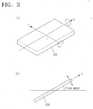
- FIGS. 3A and 3B show the process of varying pitch and roll of the fluxgate sensor 200
- FIG. 4 shows the voltage values of X-axis and Y-axis fluxgates which are normalized to a range of 1 ⁇ -1.
- the roll angle changes from 0° to 360°
- the pitch angle changes from 0° to 360°
- the fluxgate sensor 200 may be rotated in the z-axis, which is perpendicular to the x-y plane, and in this case, yaw angle changes.
- the jig is used as a measurement equipment, which mounts a certain device thereon and varies the sloping angle.
- FIG. 4 shows the actual digital voltages of the X-axis and Y-axis fluxgates which are normalized.
- 'Xf max and Xf min ' and 'Yf max and Yf min ' refer to maximum and minimum values which are measured with the pitch and roll angles fixed to 0° (that is, in an equilibrium state) and with yaw angle varying.
- FIG. 4 shows the X-axis fluxgate voltage values represented in the form of cos-function graph 301, and the Y-axis fluxgate voltage values represented in the form of sin-function graph 302.
- a developer of the neural network needs as much data as is sufficient for training of the network. Therefore, the developer is advised to adjust the angle of the jig having the fluxgate sensor 200 thereon at minutely varying degrees, and measure the X-axis and Y-axis fluxgate voltage values to construct a detailed data sheet.
- FIG. 5 shows one example of the constructed data sheet. It can be understood from FIG. 5 that the voltage values were measured in every rotation of the fluxgate sensor 200 by 5° of roll angle and with the pitch angle fixed at 30°. First, in the state that the pitch angle is at 30° and the roll angle is at -10°, the fluxgate sensor 200 is rotated with variation of yaw angle ⁇ by 5° intervals.
- the X-axis fluxgate output and Y-axis fluxgate output are measured and recorded in every varying yaw angle, and cos( ⁇ ) and sin( ⁇ ) corresponding to each yaw angle ⁇ are computed and recorded.
- the values of cos( ⁇ ) and sin( ⁇ ) can be defined as reference values of the X-axis and Y-axis fluxgates.
- FIG. 6 shows the graphical representation of the data sheet, illustrating the actual X-axis fluxgate voltage values 501 and Y-axis fluxgate voltage values 601, and reference values 502 and 602.
- FIGS. 7 and 8 illustrate the concept of neural network training by applying the data sheet of FIG. 5.
- FIG. 9 shows a graphical representation in which the X-axis and Y-axis fluxgate voltage values are calibrated to reference values by the use of a weight matrix of the learned neural network. This will be described in detail below.
- FIG. 10 shows a flowchart of a method of computing azimuth angle by using the fluxgate sensor 200 according to an exemplary embodiment of the present invention.
- the fluxgate sensor 200 is rotated from an initial equilibrium, measuring and normalizing maximum and minimum values of the X-axis and Y-axis fluxgate voltage values for the computation of azimuth angle (step S910).
- the detailed methods and equations for the measurement and normalization have already been described above.
- a data sheet is made, with varying the pitch, roll and yaw angles of the fluxgate sensor 200 in order (step S920).
- the data of the data sheet become input values and reference values of the neural network, it is advisable that data are recorded as much as possible.
- FIG. 5 shows one example of the data sheet. As shown, the X-axis and Y-axis fluxgate voltage values are measured with varying the yaw angle by 5° intervals, and then the X-axis and Y-axis fluxgate voltage values are measured with varying the roll angle by 5° intervals.
- the X-axis and Y-axis fluxgate voltage values are measured with varying the pitch, roll and yaw angles, while cos-function values and sin-function values are obtained with respect to the respective yaw angle and added to the data sheet.
- the function value become the reference values of the neural network.
- a neural network weight matrix is made, by the training of the neural network based on the data sheet (step S930).
- the training of the neural network is shown in FIGS. 7 and 8.
- a neural network is constructed of basic units which are designed based on the models of neuron activity, and input values in the respective units are combined and output as a single output value through a predetermined combination of functions. According to a weighted summation which takes into consideration and applies weights, inputs of the respective units are multiplied by weights, and summed to an output value.
- the respective units comprise three layers, that is, input end, hidden node and output end.
- the input layer which is at the left-hand side of FIGS. 7 and 8, is where the external values are inputted.
- the hidden node (or hidden layer) is named as 'hidden' because it is not connected to an input or output of the network.
- the respective units of the hidden node are completely connected to the units of the input layer. Because a network comprises standard units, the respective units of the hidden node can be obtained by multiplying the respective input values by weights. Then an output value is computed by summing the results and then applying the sum to a sigmoid function.
- the training of the neural network is the process of applying the most optimum weight to the respective inputs of respective units. This process aims to bring the results of the network to the proximity of a desired output value as close as possible.
- One of the most general technologies which have been used so far for this process is a backprogagation, which calibrates weights.
- the backprogagation computes an output value by using the weights of the network, and then computes an error by comparing a difference between the computed result with an actual result. If the error exceeds a predetermined range, the error is reversely transmitted through the network, and as a result, a weight is adjusted to minimize the error. As the optimum weight is obtained by the above process, the weight is recorded and therefore, a neural network weight matrix is made.
- FIG. 7 explains the process of training an X-axis fluxgate voltage value.
- h_c(j) denotes a (j)th hidden node
- x_c(i) is an input value of an (i)th input end.
- Outputs from the respective hidden nodes are summed and outputted as a cos-function value through an output end.
- w_c_ij(i, j) denotes a weight between the (i)th input end and (j)th hidden node
- w_cjk(j, k) refers to a weight between the (j)th hidden node and (k)th output end.
- h_s(j) denotes a (j)th hidden node for obtaining a sin-function value
- x_s(i) denotes an input value of the (i)th input end.
- the outputs from the respective hidden nodes are summed and outputted as a sin-function value through an output end
- w_s_ij(i, j) refers to a weight between the (i)th input end and (j)th hidden node.
- w_s_jk(j, k) denotes a weight between the (j)th hidden node and the (k)th output end.
- a forward process of the neural network refers to a process in which X-axis and Y-axis fluxgate voltage values of the data sheet as shown in FIG. 5 are consecutively inputted to the input end so that outputs can be obtained by applying weights and sigmoid function. The outputs as obtained are compared with the reference values of the data sheet as shown in FIG. 5. If the reference value and the output value exceed a predetermined allowable range, a backward process is performed to correct the weights.
- the training of the neural network is performed by repeating the forward and backward processes using pre-measured input values and output values.
- the training of the neural network continues until it reaches a predetermined allowable error range, and if so, the weights as obtained are consecutively recorded and stored as a weight matrix.
- the weights of the weight matrix are the most optimum weights which can calibrate the X-axis and Y-axis fluxgate voltage values to optimum cos-function and sin-function values.
- FIG. 9 illustrates in graphical representation the signal processing based on the training as described above.
- a curve 710 represents the actual X-axis fluxgate voltage values calibrated near to optimum values by using the neural network
- a curve 720 represents the optimum cos-function values, that is, optimum reference values.
- a curve 810 represents the actual Y-axis fluxgate voltage values calibrated near to the optimum values by using the neural network
- a curve 820 represents the optimum sin-function values, that is, optimum reference values.
- the weight matrix, obtained from the training, are stored from the PC of a developer to the memory 220 of the fluxgate sensor 220 in operation S940.
- the training of the neural network is a quite complicated computational process, and therefore, it is difficult to directly execute the process in the control unit 210 of the fluxgate sensor 200. Accordingly, a weight matrix may be made separately, and the control unit 210 can use such prepared matrix.
- the user turns on the fluxgate sensor 200, and measures current X-axis and Y-axis fluxgate voltage values in operation S950.
- the control unit 210 reads weights corresponding to the measured X-axis and Y-axis fluxgate voltages from the memory 220, and the forward processing of the neural network is performed in operation S960.
- the X-axis and Y-axis fluxgate voltages are calibrated to optimum cos-function and sin-function values (cos ⁇ and sin ⁇ ).
- FIG. 10 shows the operations S910 through S940 carried out by the developer of the fluxgate sensor.
- an operator purchases a fluxgate sensor 200 which has the weight matrix stored in the memory, and measures the current azimuth angle by taking the operations S950 through S970. More specifically, the operator turns on the fluxgate sensor 200 and measures the two-axis fluxgate voltage values, and the measured voltage values are calibrated to the stored weight matrix. Therefore, an accurate azimuth angle is obtained.
- the fluxgate sensor itself can measure accurate azimuth angle even on a slope, without requiring a slope measuring sensor. Because a slope sensor can be omitted, a compact-sized and economical fluxgate sensor which consumes less power, can be provided. Accordingly, the portable fluxgate sensor can be provided. Furthermore, while the conventional slope sensor frequently has an error in the measurement of azimuth angle due to inaccurate recognition of the sloping degree of the fluxgate sensor, according to the present invention, the fluxgate sensor can guarantee accurate azimuth information even in motion, because it needs not measure the sloping degree.
Landscapes
- Physics & Mathematics (AREA)
- Engineering & Computer Science (AREA)
- Radar, Positioning & Navigation (AREA)
- Remote Sensing (AREA)
- General Physics & Mathematics (AREA)
- Life Sciences & Earth Sciences (AREA)
- Environmental & Geological Engineering (AREA)
- General Life Sciences & Earth Sciences (AREA)
- Geology (AREA)
- Electromagnetism (AREA)
- Condensed Matter Physics & Semiconductors (AREA)
- Measuring Magnetic Variables (AREA)
Applications Claiming Priority (2)
| Application Number | Priority Date | Filing Date | Title |
|---|---|---|---|
| KR1020030079312A KR100555668B1 (ko) | 2003-11-11 | 2003-11-11 | 경사진 환경에서 방위각 측정이 가능한 플럭스게이트지자기 센서 및 그 측정 방법 |
| KR2003079312 | 2003-11-11 |
Publications (2)
| Publication Number | Publication Date |
|---|---|
| EP1531336A2 true EP1531336A2 (de) | 2005-05-18 |
| EP1531336A3 EP1531336A3 (de) | 2006-10-11 |
Family
ID=34431750
Family Applications (1)
| Application Number | Title | Priority Date | Filing Date |
|---|---|---|---|
| EP20040255783 Withdrawn EP1531336A3 (de) | 2003-11-11 | 2004-09-22 | Förstersonde zur Azimuthmessung und Azimuthmessungsverfahren |
Country Status (4)
| Country | Link |
|---|---|
| US (1) | US7363185B2 (de) |
| EP (1) | EP1531336A3 (de) |
| JP (2) | JP4718821B2 (de) |
| KR (1) | KR100555668B1 (de) |
Cited By (2)
| Publication number | Priority date | Publication date | Assignee | Title |
|---|---|---|---|---|
| EP1762858B1 (de) * | 2005-09-12 | 2010-11-17 | Sanyo Electric Co., Ltd. | Erregerspulenansteuerung eines Magnetsensors |
| EP1762859B1 (de) * | 2005-09-12 | 2011-01-19 | Sanyo Electric Co., Ltd. | Erfassungsschaltung für Magnetfelddetektor |
Families Citing this family (4)
| Publication number | Priority date | Publication date | Assignee | Title |
|---|---|---|---|---|
| KR100555656B1 (ko) * | 2003-08-27 | 2006-03-03 | 삼성전자주식회사 | 복각 검출 기능을 지원하는 지자기 센서 및 그 검출 방법 |
| TWI513993B (zh) | 2013-03-26 | 2015-12-21 | Ind Tech Res Inst | 三軸磁場感測器、製作磁場感測結構的方法與磁場感測電路 |
| US10915248B1 (en) * | 2019-08-07 | 2021-02-09 | Macronix International Co., Ltd. | Memory device |
| CN114675335B (zh) * | 2022-03-15 | 2025-08-12 | 紫金矿业集团股份有限公司 | 一种基于机器学习的磁通门航磁数据的处理方法 |
Family Cites Families (16)
| Publication number | Priority date | Publication date | Assignee | Title |
|---|---|---|---|---|
| JPH03501159A (ja) * | 1987-04-14 | 1991-03-14 | イギリス国 | ロールの影響を受けない磁力計システム |
| US4929899A (en) * | 1988-02-24 | 1990-05-29 | Boeing Company | Fluxgate magnetometer apparatus and adjustment method to maintain accuracy over a wide temperature range |
| JPH0571713U (ja) * | 1992-02-28 | 1993-09-28 | サンデン株式会社 | 磁気方位検出装置 |
| DE4439945C1 (de) * | 1994-11-09 | 1996-02-08 | Leica Ag | Verfahren zur Stabilisierung der Richtungsanzeige von Magnetkompassen |
| US5812992A (en) * | 1995-05-24 | 1998-09-22 | David Sarnoff Research Center Inc. | Method and system for training a neural network with adaptive weight updating and adaptive pruning in principal component space |
| JPH09304065A (ja) * | 1996-05-14 | 1997-11-28 | Toshiba Corp | 航空機位置検出装置 |
| JPH09325029A (ja) | 1996-06-05 | 1997-12-16 | Fuji Heavy Ind Ltd | 地磁気センサの補正装置 |
| JPH10153428A (ja) * | 1996-11-22 | 1998-06-09 | Alps Electric Co Ltd | 車両方位検出装置 |
| JPH10318752A (ja) * | 1997-05-20 | 1998-12-04 | Software Sekkei:Kk | 移動体または回転体の方位測定装置 |
| JP3032776B2 (ja) * | 1997-12-19 | 2000-04-17 | 防衛庁技術研究本部長 | 通過位置検出方法及び通過位置検出装置 |
| JP2001304910A (ja) * | 2000-04-27 | 2001-10-31 | Tokin Corp | 方位表示装置 |
| JP3857499B2 (ja) * | 2000-05-12 | 2006-12-13 | セイコーインスツル株式会社 | 電子方位計の補正機構、これを備えた電子方位計及び電子方位計付電子時計 |
| CN1152237C (zh) * | 2001-03-30 | 2004-06-02 | 清华大学 | 基于微机电技术的微型导航系统 |
| JP2003121518A (ja) * | 2001-10-16 | 2003-04-23 | Mitsubishi Electric Corp | 磁力計 |
| JP3675393B2 (ja) * | 2001-11-22 | 2005-07-27 | ヤマハ株式会社 | 電子装置 |
| KR100481552B1 (ko) * | 2002-07-30 | 2005-04-07 | 삼성전기주식회사 | 2축 자계검출소자가 집적된 인쇄회로기판 및 그 제조방법 |
-
2003
- 2003-11-11 KR KR1020030079312A patent/KR100555668B1/ko not_active Expired - Fee Related
-
2004
- 2004-09-22 EP EP20040255783 patent/EP1531336A3/de not_active Withdrawn
- 2004-10-28 US US10/974,740 patent/US7363185B2/en not_active Expired - Fee Related
- 2004-11-09 JP JP2004324899A patent/JP4718821B2/ja not_active Expired - Fee Related
-
2007
- 2007-06-20 JP JP2007163202A patent/JP2007304105A/ja active Pending
Non-Patent Citations (1)
| Title |
|---|
| None |
Cited By (2)
| Publication number | Priority date | Publication date | Assignee | Title |
|---|---|---|---|---|
| EP1762858B1 (de) * | 2005-09-12 | 2010-11-17 | Sanyo Electric Co., Ltd. | Erregerspulenansteuerung eines Magnetsensors |
| EP1762859B1 (de) * | 2005-09-12 | 2011-01-19 | Sanyo Electric Co., Ltd. | Erfassungsschaltung für Magnetfelddetektor |
Also Published As
| Publication number | Publication date |
|---|---|
| KR100555668B1 (ko) | 2006-03-03 |
| US20050114076A1 (en) | 2005-05-26 |
| US7363185B2 (en) | 2008-04-22 |
| KR20050045299A (ko) | 2005-05-17 |
| EP1531336A3 (de) | 2006-10-11 |
| JP2005148066A (ja) | 2005-06-09 |
| JP2007304105A (ja) | 2007-11-22 |
| JP4718821B2 (ja) | 2011-07-06 |
Similar Documents
| Publication | Publication Date | Title |
|---|---|---|
| US7755353B2 (en) | Three-axis fluxgate-type magnetism detecting device | |
| JP2007248477A (ja) | 勾配の影響を補償し方位角を演算する地磁気センサー、およびその演算方法 | |
| US5170566A (en) | Means for reducing interference among magnetometer array elements | |
| JP4047335B2 (ja) | 伏角検出機能をサポートする地磁気センサおよびその方法 | |
| US10746570B2 (en) | Mass displacement estimation using back EMF and magnetic reference crossing | |
| US7168176B2 (en) | Geomagnetic sensor for informing users whether detected azimuth angle is acceptable, and a method thereof | |
| JP3934633B2 (ja) | 伏角検出機能を支援する地磁気センサー及びその検出方法 | |
| JP2007304105A (ja) | 傾斜している環境で方位角測定の可能なフラックスゲート地磁気センサー及びその測定方法 | |
| JP2006170997A (ja) | 方位角を測定する地磁気センサ及びその方法 | |
| US11828818B2 (en) | Method calibrating magnetometer and magnetometer calibration device | |
| US20260079494A1 (en) | State estimation method for mobile robot navigation | |
| KR20070102152A (ko) | 내부 자계에 의한 왜곡이 보정된 휴대용 단말기 및 그 내부자계 왜곡 보정 방법 | |
| WO2009025404A1 (en) | Measurement position and time recording type magnetometer and method of measuring magnetic field using the same |
Legal Events
| Date | Code | Title | Description |
|---|---|---|---|
| PUAI | Public reference made under article 153(3) epc to a published international application that has entered the european phase |
Free format text: ORIGINAL CODE: 0009012 |
|
| AK | Designated contracting states |
Kind code of ref document: A2 Designated state(s): AT BE BG CH CY CZ DE DK EE ES FI FR GB GR HU IE IT LI LU MC NL PL PT RO SE SI SK TR |
|
| AX | Request for extension of the european patent |
Extension state: AL HR LT LV MK |
|
| PUAL | Search report despatched |
Free format text: ORIGINAL CODE: 0009013 |
|
| AK | Designated contracting states |
Kind code of ref document: A3 Designated state(s): AT BE BG CH CY CZ DE DK EE ES FI FR GB GR HU IE IT LI LU MC NL PL PT RO SE SI SK TR |
|
| AX | Request for extension of the european patent |
Extension state: AL HR LT LV MK |
|
| RIC1 | Information provided on ipc code assigned before grant |
Ipc: G01R 33/04 20060101AFI20050208BHEP Ipc: G01C 17/38 20060101ALI20060906BHEP |
|
| 17P | Request for examination filed |
Effective date: 20070221 |
|
| AKX | Designation fees paid |
Designated state(s): AT BE BG CH CY CZ DE DK EE ES FI FR GB GR HU IE IT LI LU MC NL PL PT RO SE SI SK TR |
|
| 17Q | First examination report despatched |
Effective date: 20101005 |
|
| RAP1 | Party data changed (applicant data changed or rights of an application transferred) |
Owner name: SAMSUNG ELECTRONICS CO., LTD. |
|
| STAA | Information on the status of an ep patent application or granted ep patent |
Free format text: STATUS: THE APPLICATION IS DEEMED TO BE WITHDRAWN |
|
| 18D | Application deemed to be withdrawn |
Effective date: 20170401 |