EP1531455A2 - Procédé pour former le faisceau d'un réseau de transducteurs - Google Patents
Procédé pour former le faisceau d'un réseau de transducteurs Download PDFInfo
- Publication number
- EP1531455A2 EP1531455A2 EP04025031A EP04025031A EP1531455A2 EP 1531455 A2 EP1531455 A2 EP 1531455A2 EP 04025031 A EP04025031 A EP 04025031A EP 04025031 A EP04025031 A EP 04025031A EP 1531455 A2 EP1531455 A2 EP 1531455A2
- Authority
- EP
- European Patent Office
- Prior art keywords
- delay times
- value
- corrected
- magnitude
- group signal
- Prior art date
- Legal status (The legal status is an assumption and is not a legal conclusion. Google has not performed a legal analysis and makes no representation as to the accuracy of the status listed.)
- Withdrawn
Links
Images

Classifications
-
- G—PHYSICS
- G01—MEASURING; TESTING
- G01S—RADIO DIRECTION-FINDING; RADIO NAVIGATION; DETERMINING DISTANCE OR VELOCITY BY USE OF RADIO WAVES; LOCATING OR PRESENCE-DETECTING BY USE OF THE REFLECTION OR RERADIATION OF RADIO WAVES; ANALOGOUS ARRANGEMENTS USING OTHER WAVES
- G01S3/00—Direction-finders for determining the direction from which infrasonic, sonic, ultrasonic or electromagnetic waves, or particle emission, not having a directional significance, are being received
- G01S3/80—Direction-finders for determining the direction from which infrasonic, sonic, ultrasonic or electromagnetic waves, or particle emission, not having a directional significance, are being received using ultrasonic, sonic or infrasonic waves
- G01S3/802—Systems for determining direction or deviation from predetermined direction
- G01S3/808—Systems for determining direction or deviation from predetermined direction using transducers spaced apart and measuring phase or time difference between signals therefrom, i.e. path-difference systems
- G01S3/8083—Systems for determining direction or deviation from predetermined direction using transducers spaced apart and measuring phase or time difference between signals therefrom, i.e. path-difference systems determining direction of source
-
- G—PHYSICS
- G10—MUSICAL INSTRUMENTS; ACOUSTICS
- G10K—SOUND-PRODUCING DEVICES; METHODS OR DEVICES FOR PROTECTING AGAINST, OR FOR DAMPING, NOISE OR OTHER ACOUSTIC WAVES IN GENERAL; ACOUSTICS NOT OTHERWISE PROVIDED FOR
- G10K11/00—Methods or devices for transmitting, conducting or directing sound in general; Methods or devices for protecting against, or for damping, noise or other acoustic waves in general
- G10K11/18—Methods or devices for transmitting, conducting or directing sound
- G10K11/26—Sound-focusing or directing, e.g. scanning
- G10K11/34—Sound-focusing or directing, e.g. scanning using electrical steering of transducer arrays, e.g. beam steering
- G10K11/341—Circuits therefor
- G10K11/346—Circuits therefor using phase variation
Definitions
- the invention relates to a method for forming a Group signal of a directional characteristic of a Converter arrangement in the preamble of claim 1 defined genus.
- the so-called beamforming, of nonlinear Antennas become the received signals for the purpose of their time - delayed as if the incident sound wave front the group of common operated electroacoustic transducer at their fictitious location on one to the main direction of the directional characteristic right-angled aligned line simultaneously.
- the fictional places are made by rectangular projection of the actual locations of the transducers on the said line receive.
- the size of the individual delay time for each transducer is expressed as a quotient of the length of the Projection beam, so the distance of the fictitious location of Transducer from the actual transducer location, and an assumed transducer location mean value of the speed of sound.
- the calculated time delays become common to all group signals stored for different directions of arrival the sound waves have been formed.
- Main direction of the directional characteristic the direction of incidence the sound waves received by the transducer assembly determined, and with side lobes or side lobes, by an amplitude graduation of the time-delayed samples, the so-called shading, e.g. by a Dolph-Chebyshev weighting, be reduced.
- the transducer through which the transducers cover acoustically transparent envelope By changing the speed of sound in the field of application of Transducer arrangement, by exceeding installation tolerances the transducer through which the transducers cover acoustically transparent envelope, its thickness and material constant may have relatively large tolerances, the soft calculated and stored delay times more or less dependent on the correct delay times, so that the addition of the received signals is no longer accurate Conphas takes place. This reduces the maximum Receive level of the group signal, ie the output level of the Beamformer.
- the directional characteristic is not exact formed, and accordingly is the bearing of a sound source fraught with more or less big mistake.
- the invention is based on the object in a method of the type mentioned above for an exact Direction formation required, correct, individual Delay times for the received signals of the converter as well with changing boundary conditions, like variation of the Speed of sound or unrecognizable geometry errors in the transducer assembly to determine exactly.
- the inventive method has the advantage that the Beamforming, ie the formation of the group signal of Directional characteristic of the transducer arrangement, with correct Delay times is carried out by the individual Case of application are adapted, so that the output signal of Beamformers is always maximum.
- the inventive method takes advantage of the fact that the output level or the output power or another characteristic quantity the output signal of the beamformer, that is the group signal, is maximum only with correctly calculated delay times.
- the group signal is a first magnitude value, e.g. a first level value, with respect to the Initial delay times reduced delay times and a second size value, e.g. a second level value, with compared to the Clearverzögerungsterrorism enlarged Delay times determined.
- the two size values, e.g. Level value become the one with the Clearverzögerungs founded certain original size value, the Original size value, e.g. Source level value, in relation set.
- the latter can with two alternatives Procedures are carried out in the claims. 4 and 5 and 6 and 7 are given.
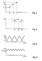
- Embodiment of a transducer assembly 10 the groups of jointly operated electroacoustic transducers 11 has, which are arranged on a curved support 12, a so-called cylinder base is used on its cylindrical surface For example, 21 transducers 11 equidistant in the circumferential direction are arranged on a circular line. How not next are shown are usually to achieve a vertical focusing of the transducer array, i. one smallest possible vertical opening angle of Cylinder base, several in the axial direction of the cylinder underlying transducers to a so-called. Stave summarized. Each of the twenty-one transducers 11 in FIG. 1 belongs to a Stave.
- a group of common operated converters 11 or staves includes in Embodiment of FIG. 1 eight transducers 11 and staves.
- the Group signal has the group of eight jointly operated electroacoustic transducer 11 or Staves a Directional characteristic whose main direction in Fig. 1 with I is marked.
- This directional characteristic of Transducer group also called group characteristic, becomes the horizontal scanning of the environment of the cylinder base pivoted electronically, adding by adding a Transducer 11 at one end of the transducer group and take away a transducer 11 at the other end of the transducer group the Main direction I of the directional characteristic horizontal can be rotated gradually 360 °.
- a sound wavefront emitted by a sound source passes over the individual transducers 11, and the jointly operated eight transducers 11 of the transducer group each provide at their output a corresponding electrical output signal, which is referred to below as a received signal.
- the received signals are time-delayed in a known manner and added to the group signal in a concave manner.
- the delay time t i for each of the received signals is calculated as a quotient of the distance a i and the speed of sound c.
- the distance a i for each transducer 11 of the eight jointly operated transducers 11 results from the projection of the actual location of the electroacoustic transducer 11 on the carrier 12 along the main direction I onto a straight line 13 which represents the locations of the first and last converter 11 of the group connects to each other.
- the distance a i is the length of the respective projection beam. This results in the delay time t 2 for the second transducer 11 in the group of eight transducers to a 2 / c, the delay time t 3 for the third transducer 11 in the transducer group to a 3 / c, etc., where for c a mean speed of sound Is accepted.
- This set of delay times t i in the following referred to as ⁇ 0 , is stored in a memory.
- an equal set of delay times are stored for all the pivoted main directions of the directional characteristic of the transducer groups formed on the cylinder base of eight transducers.
- the set of stored delay times ⁇ 0, however, may deviate more or less from the correct time delay times, for example by deviating the speed of sound in the field of use from the mean sound velocity underlying the calculation by non-compliance with installation tolerances of the converters within the cylinder base , by influences of the enveloping body which covers the transducer arrangement etc.
- the group signal with the correct delay times now becomes a size of the group signal formed with the stored set of calculated delay times ⁇ 0 , eg the magnitude, the power or the level of the group signal, selected as the evaluation variable for the group signal and the stored delay times ⁇ 0 as long as reduced and increased until the considered size of the group signal reaches a maximum value.
- the maximum of the size considered is an indication that now the correct delay times have been set, which give the correct, the directional characteristic of the transducer assembly-determining group signal.
- Size of the group signal is the level P of the Group signal selected.
- the reduction or enlargement of the first delay times is performed with an average sound velocity c increased or decreased by a constant increment .DELTA.c.
- the level values P -1 and P +1 are determined in the same way as the original level value P 0 by delaying and adding the received signals of the transducers 11 by the reduced delay times.
- FIG. 2 shows the two level values P -1 and P +1 determined with reduced delay times ⁇ -1 and increased delay times ⁇ +1 together with the original level value P 0 , which was determined using the stored first delay times ⁇ 0 .
- the first and second level value P -1 and P +1 are now set with respect to the origin level value P 0, here compared to the level value P 0 with respect to their size. If the first or second level value is smaller and the second or first level value is greater than the original level value P 0 , ie the level value P 0 is not greater than both level values P -1 and P +1 , then this is an indication that the original level value P 0 is not maximal. This is the case with the level values shown in FIG.
- the stored first deceleration values ⁇ 0 are then changed, for example by changing the value of the average sound velocity, whereby the individual delay times t 2 to t 7 in the set ⁇ 0 of the stored delay times are changed accordingly.
- the received signals are time-delayed and in turn added and the corrected original level value P * 0 of the group signal thus obtained is formed.
- the method steps described above namely determination of a new first and second level value P * -1 and P * +1 , are repeated by adding the received signals, which have been delayed with reduced or increased delay times compared to the corrected first delay times ⁇ * 0 .
- the corrected original level P * 0 and the two new level values P * -1 and P * +1 are again compared with each other. If it is found in this comparison that the corrected original level value P * 0 is greater than the two new level values P * -1 and P * +1 , this is an indication that the corrected original level value P * 0 is now maximal.
- the stored delay times ⁇ 0 are corrected again. This is repeated until the conditions according to FIG. 3 have occurred, that is to say the last corrected corrected original level value P * 0 is greater than the two new level values P * -1 and P * calculated with the reduced and enlarged corrected delay times ⁇ * 0 . +1 .
- the correction of the first delay times ⁇ 0 occurs at longer delay times when the second level value P +1 is greater than the original level value P 0 , and at smaller delay times when the second level value P +1 is smaller than the original level value P 0 .
- the first and second level values P -1 and P +1 calculated in relation to the initial level value P 0 calculated with the stored first delay times ⁇ 0 are not compared by magnitude comparison of the level values, but by means of a frequency analysis.
- the level values P -1 , P 0 and P +1 shown in FIG. 2 are sampled backwards and forwards several times in the mentioned sequences and the sequence of the sampled values, as shown in FIG. 4, is subjected to a frequency analysis.
- the spectral frequency determined by the frequency analysis is compared with the sampling frequency. If the spectral frequency is less than twice the sampling frequency, this is an indication that the original level value P 0 is not a maximum.
- the set of stored first delay times ⁇ 0 is again changed, and the received signals delayed by the corrected first delay times ⁇ 0 of the converters are added to the corrected group signal and the level P * 0 of the corrected group signal is determined.
- the received signals with delay times which are once reduced compared to the corrected first delay times and once enlarged, delayed and added to group signals and from the new level values P * -1 and P * +1 determined, as eg Fig. 3 are shown.
- These level values are sampled again in the same way, and the sequence of samples, as shown for example in FIG. 5, is subjected to a frequency analysis. If the spectral frequency determined with the frequency analysis is equal to twice the sampling frequency, as assumed in the example of FIGS. 4 and 5, then the changed original level value P * 0 represents a maximum.
- the optimal direction of the correction of the first delay times ⁇ 0 ie to know whether the first delay times ⁇ 0 must be shifted to larger or smaller delay times to the maximum of the level value of the group signal to reach.
- the phase of the Fourier signal obtained from a complex Fourier transformation of the sequence of samples is determined. If the phase is positive, the first delay times ⁇ 0 are increased, if it is negative, the first delay times are reduced. This is also applied in the same way to the respective corrected first delay times ⁇ * 0 , specifically until the spectral frequency is equal to twice the sampling frequency, the last modified original level value P * 0 being maximum.
- converter arrangements which are non-linear, i. at Transducer assemblies in which the converter is not on a elongated, straight beam or a flat surface are arranged, and the at least partially converter or staves, which with respect to a Sound incidence direction axis or mirror symmetry are arranged.
- Such converters are the so-called cylinder bases, where the transducers are in staves about the circumference of a Cylinders are arranged distributed, or so-called.
- Conformal Arrays as they are preferably on underwater running bodies are arranged and at the bow or head one to the pre-alignment have symmetrical arrangement of the transducer.
Landscapes
- Physics & Mathematics (AREA)
- Engineering & Computer Science (AREA)
- General Physics & Mathematics (AREA)
- Radar, Positioning & Navigation (AREA)
- Remote Sensing (AREA)
- Acoustics & Sound (AREA)
- Multimedia (AREA)
- Measurement Of Velocity Or Position Using Acoustic Or Ultrasonic Waves (AREA)
- Circuit For Audible Band Transducer (AREA)
Applications Claiming Priority (2)
| Application Number | Priority Date | Filing Date | Title |
|---|---|---|---|
| DE2003153292 DE10353292B3 (de) | 2003-11-14 | 2003-11-14 | Verfahren zur Bildung eines Gruppensignals |
| DE10353292 | 2003-11-14 |
Publications (2)
| Publication Number | Publication Date |
|---|---|
| EP1531455A2 true EP1531455A2 (fr) | 2005-05-18 |
| EP1531455A3 EP1531455A3 (fr) | 2008-11-12 |
Family
ID=34428737
Family Applications (1)
| Application Number | Title | Priority Date | Filing Date |
|---|---|---|---|
| EP04025031A Withdrawn EP1531455A3 (fr) | 2003-11-14 | 2004-10-21 | Procédé pour former le faisceau d'un réseau de transducteurs |
Country Status (2)
| Country | Link |
|---|---|
| EP (1) | EP1531455A3 (fr) |
| DE (1) | DE10353292B3 (fr) |
Cited By (3)
| Publication number | Priority date | Publication date | Assignee | Title |
|---|---|---|---|---|
| RU2431153C1 (ru) * | 2010-03-17 | 2011-10-10 | Открытое акционерное общество "Дальприбор" | Устройство компенсации кривизны фронта волны |
| EP2333574A3 (fr) * | 2009-12-03 | 2013-08-14 | ATLAS Elektronik GmbH | Procédé d'amélioration de l'exactitude de mesure, dispositif d'amélioration de l'exactitude de mesure et installation solaire |
| RU2554281C1 (ru) * | 2014-03-18 | 2015-06-27 | Открытое акционерное общество "Концерн "Океанприбор" | Многоэлементная гидроакустическая антенна |
Families Citing this family (3)
| Publication number | Priority date | Publication date | Assignee | Title |
|---|---|---|---|---|
| DE102006019588B3 (de) * | 2006-04-27 | 2007-10-18 | Atlas Elektronik Gmbh | Verfahren zur Peilung von schallabstrahlenden Zielen |
| DE102007046803A1 (de) * | 2007-09-29 | 2009-04-02 | Atlas Elektronik Gmbh | Sonareinrichtung |
| DE102011117591B4 (de) | 2011-11-03 | 2013-12-24 | Atlas Elektronik Gmbh | Verfahren und Vorrichtung zum Korrigieren systematischer Peilfehler |
Family Cites Families (7)
| Publication number | Priority date | Publication date | Assignee | Title |
|---|---|---|---|---|
| US4060792A (en) * | 1976-06-17 | 1977-11-29 | Raytheon Company | Hard clipped beam former |
| US4058003A (en) * | 1976-07-21 | 1977-11-15 | The Board Of Trustees Of The Leland Stanford Junior University | Ultrasonic electronic lens with reduced delay range |
| US4208916A (en) * | 1978-09-13 | 1980-06-24 | Picker Corporation | Electronic ultrasonic sector scanning apparatus and method |
| GB2042725B (en) * | 1979-02-21 | 1983-02-16 | Sperry Corp | Sonar detection system |
| US4815047A (en) * | 1986-06-20 | 1989-03-21 | Hewlett-Packard Company | Synthetic focus annular array transducer |
| US5357962A (en) * | 1992-01-27 | 1994-10-25 | Sri International | Ultrasonic imaging system and method wtih focusing correction |
| DE10027538C1 (de) * | 2000-06-02 | 2001-10-31 | Stn Atlas Elektronik Gmbh | Verfahren zum Bestimmen der Einfallsrichtung von Schallwellen |
-
2003
- 2003-11-14 DE DE2003153292 patent/DE10353292B3/de not_active Expired - Fee Related
-
2004
- 2004-10-21 EP EP04025031A patent/EP1531455A3/fr not_active Withdrawn
Cited By (3)
| Publication number | Priority date | Publication date | Assignee | Title |
|---|---|---|---|---|
| EP2333574A3 (fr) * | 2009-12-03 | 2013-08-14 | ATLAS Elektronik GmbH | Procédé d'amélioration de l'exactitude de mesure, dispositif d'amélioration de l'exactitude de mesure et installation solaire |
| RU2431153C1 (ru) * | 2010-03-17 | 2011-10-10 | Открытое акционерное общество "Дальприбор" | Устройство компенсации кривизны фронта волны |
| RU2554281C1 (ru) * | 2014-03-18 | 2015-06-27 | Открытое акционерное общество "Концерн "Океанприбор" | Многоэлементная гидроакустическая антенна |
Also Published As
| Publication number | Publication date |
|---|---|
| DE10353292B3 (de) | 2005-05-19 |
| EP1531455A3 (fr) | 2008-11-12 |
Similar Documents
| Publication | Publication Date | Title |
|---|---|---|
| DE19581713B4 (de) | Basisbandprozessor eines Empfangsstrahlformersystems | |
| DE69106049T2 (de) | Ultraschallbildgerät mit adaptiver Phasenaberrationskorrektur. | |
| EP1473967B1 (fr) | Procédé de suppression d'au moins un signal de bruit acoustique et dispositif de mise en oeuvre d'un tel procédé | |
| DE3303288C2 (de) | Ultraschall-diagnostisches Tomographiegerät | |
| DE60113732T2 (de) | Verfahren zur erzeugung eines elektrischen ausgangssignals und akustisch/elektrisches wandlungssystem | |
| DE10353292B3 (de) | Verfahren zur Bildung eines Gruppensignals | |
| EP0959367A2 (fr) | Procédé de formation spatiale de faisceau hertzien dans des systèmes de repérage | |
| DE19648327B4 (de) | Verfahren zur Richtstrahlbildung in Peilanlagen und Vorrichtung zur Durchführung des Verfahrens | |
| EP2010936B1 (fr) | Procédé de repérage de cibles émettant des sons | |
| DE3854303T2 (de) | Ultraschall-diagnosegerät. | |
| DE10027538C1 (de) | Verfahren zum Bestimmen der Einfallsrichtung von Schallwellen | |
| DE19627218B4 (de) | Radarvorrichtung | |
| DE2202517C3 (de) | Verfahren zur Peilung periodisch wiederkehrender impulsförmiger Signale | |
| DE69410196T2 (de) | Verfahren zur Strahlungskeulenkompression von Radarantennendiagrammen | |
| DE10153443C1 (de) | Verfahren zur passiven Ortung von schallabstrahlenden Zielen | |
| EP1176428B1 (fr) | Procede pour ameliorer le rapport signal sur bruit d'un réseau d'antennes sonar | |
| EP2480907B1 (fr) | Procédé et dispositif de localisation de cibles émettant un rayonnement | |
| EP3082273B1 (fr) | Procédé et dispositif de réduction de signaux parasites corrélés dans des systèmes de réception multi-canaux à formation de faisceau numérique | |
| EP2333574B1 (fr) | Procédé d'amélioration de l'exactitude de mesure, dispositif d'amélioration de l'exactitude de mesure et installation sonar | |
| DE69307945T2 (de) | Lineare Antennengruppe mit konstanter Richtcharakteristik und Vorrichtung zur Strahlformung für eine solche Antenne | |
| DE19629689C1 (de) | Verfahren zum Bilden von Gruppensignalen | |
| DE4414831A1 (de) | Meßanordnung mit mindestens zwei Meßkanälen | |
| DE102007046803A1 (de) | Sonareinrichtung | |
| DE102010061032B4 (de) | Vorrichtung zur Ortung von Quellen von Wellen mit mehreren Empfängern und einem Hohlspiegel für die Wellen | |
| DE102021006155A1 (de) | Signalverarbeitungsvorrichtung |
Legal Events
| Date | Code | Title | Description |
|---|---|---|---|
| PUAI | Public reference made under article 153(3) epc to a published international application that has entered the european phase |
Free format text: ORIGINAL CODE: 0009012 |
|
| 17P | Request for examination filed |
Effective date: 20041021 |
|
| AK | Designated contracting states |
Kind code of ref document: A2 Designated state(s): AT BE BG CH CY CZ DE DK EE ES FI FR GB GR HU IE IT LI LU MC NL PL PT RO SE SI SK TR |
|
| AX | Request for extension of the european patent |
Extension state: AL HR LT LV MK |
|
| PUAL | Search report despatched |
Free format text: ORIGINAL CODE: 0009013 |
|
| AK | Designated contracting states |
Kind code of ref document: A3 Designated state(s): AT BE BG CH CY CZ DE DK EE ES FI FR GB GR HU IE IT LI LU MC NL PL PT RO SE SI SK TR |
|
| AX | Request for extension of the european patent |
Extension state: AL HR LT LV MK |
|
| AKX | Designation fees paid |
Designated state(s): AT BE BG CH CY CZ DE DK EE ES FI FR GB GR HU IE IT LI LU MC NL PL PT RO SE SI SK TR |
|
| 17Q | First examination report despatched |
Effective date: 20100407 |
|
| STAA | Information on the status of an ep patent application or granted ep patent |
Free format text: STATUS: THE APPLICATION IS DEEMED TO BE WITHDRAWN |
|
| 18D | Application deemed to be withdrawn |
Effective date: 20100818 |