EP2480907B1 - Procédé et dispositif de localisation de cibles émettant un rayonnement - Google Patents
Procédé et dispositif de localisation de cibles émettant un rayonnement Download PDFInfo
- Publication number
- EP2480907B1 EP2480907B1 EP10742856.7A EP10742856A EP2480907B1 EP 2480907 B1 EP2480907 B1 EP 2480907B1 EP 10742856 A EP10742856 A EP 10742856A EP 2480907 B1 EP2480907 B1 EP 2480907B1
- Authority
- EP
- European Patent Office
- Prior art keywords
- dependent amplitude
- central
- directionally dependent
- function
- signal directions
- Prior art date
- Legal status (The legal status is an assumption and is not a legal conclusion. Google has not performed a legal analysis and makes no representation as to the accuracy of the status listed.)
- Not-in-force
Links
Images


Classifications
-
- G—PHYSICS
- G01—MEASURING; TESTING
- G01S—RADIO DIRECTION-FINDING; RADIO NAVIGATION; DETERMINING DISTANCE OR VELOCITY BY USE OF RADIO WAVES; LOCATING OR PRESENCE-DETECTING BY USE OF THE REFLECTION OR RERADIATION OF RADIO WAVES; ANALOGOUS ARRANGEMENTS USING OTHER WAVES
- G01S3/00—Direction-finders for determining the direction from which infrasonic, sonic, ultrasonic or electromagnetic waves, or particle emission, not having a directional significance, are being received
- G01S3/80—Direction-finders for determining the direction from which infrasonic, sonic, ultrasonic or electromagnetic waves, or particle emission, not having a directional significance, are being received using ultrasonic, sonic or infrasonic waves
- G01S3/802—Systems for determining direction or deviation from predetermined direction
- G01S3/803—Systems for determining direction or deviation from predetermined direction using amplitude comparison of signals derived from receiving transducers or transducer systems having differently-oriented directivity characteristics
-
- G—PHYSICS
- G01—MEASURING; TESTING
- G01S—RADIO DIRECTION-FINDING; RADIO NAVIGATION; DETERMINING DISTANCE OR VELOCITY BY USE OF RADIO WAVES; LOCATING OR PRESENCE-DETECTING BY USE OF THE REFLECTION OR RERADIATION OF RADIO WAVES; ANALOGOUS ARRANGEMENTS USING OTHER WAVES
- G01S3/00—Direction-finders for determining the direction from which infrasonic, sonic, ultrasonic or electromagnetic waves, or particle emission, not having a directional significance, are being received
- G01S3/80—Direction-finders for determining the direction from which infrasonic, sonic, ultrasonic or electromagnetic waves, or particle emission, not having a directional significance, are being received using ultrasonic, sonic or infrasonic waves
- G01S3/8006—Multi-channel systems specially adapted for direction-finding, i.e. having a single aerial system capable of giving simultaneous indications of the directions of different signals
Definitions
- the invention relates to a method for aiming sound-emitting targets by means of a receiving antenna referred to in the preamble of claim 1 and a corresponding type of device mentioned in the preamble of claim 6.
- the noises or reflected sound waves emitted by these targets or objects are detected by passive sound measurement methods and their direction is determined.
- the sound waves are conventionally received with a sonar receiving system, which has a plurality of electroacoustic or optoacoustic transducer for receiving sound waves and generating electrical reception signals.
- a direction generator is connected downstream of the receiving antenna in which the received signals of the transducers are added in groups to form a group signal determining a directional characteristic.
- the received signals are time-delayed by means of so-called time delay coefficients such that they are in relation to one another with respect to a main direction of the directional characteristic, and then added to form the group signal.
- the time delay coefficients are predetermined by the position of the respective transducer with respect to the main direction of the directional characteristic.
- a plurality of directional characteristics can be formed, which are all pivoted about a different size, in particular horizontal, angle against each other and against a reference plane, such as the normal plane of the antenna.
- a receiving antenna for example, linear antennas or cylinder bases are used.
- the transducers are arranged regularly along a straight line.
- the main receiving direction of this directional characteristic points in the direction of the vertical of the antenna and is pivotable by electronic means.
- non-linear antennas such as cylindrical bases
- the received signals are concurrently delayed for the purpose of their phase summation, as if the incident sound wavefront simultaneously reaches the group of jointly operated transducers at their fictitious location on a line perpendicular to the main receiving direction of the directional characteristic
- Main receiving direction by electronic means is pivotal.
- the time delay coefficients for each transducer are determined from the distance of the notional location of the transducer from the actual transducer location.
- a directional diagram The graphical representation of a directional characteristic in a sectional plane is referred to as a directional diagram. It describes the sensitivity of the antenna, for example, by plotting the output voltage as a function of the sound incidence angle and is usually normalized to a maximum value.
- the representation is either in a polar diagram or in Cartesian coordinates with either linear or logarithmic radial scaling.
- a directional diagram contains at least one main lobe and possibly several side lobes or sidelobes. Each maximum is bounded on both sides by a zero.
- the main lobe points in the main receiving direction of the antenna.
- the side lobes are usually undesirable because they affect the unique directionality of the antenna and weaken the main lobe. In order to reduce the effects of this unwanted reception, additional measures for sidelobe suppression are often made in the receiver, for example by means of a suitable shading function.
- High-resolution angle separation techniques avoid this disadvantage. With them, it is in principle possible to separate targets with small angle differences, which are below the resolution limit of the direction generator.
- a known high-resolution method is, for example, the MUSIC (Multiple Signal Classification) method. This is a so-called subspace method that first estimates the number of targets. Ideally, eigenvalues that can be assigned to the signals can be clearly separated from the eigenvalues that belong to the noise. This is used to estimate the number of received signals.
- the subspace method is adversely affected by several factors. So far, the MUSIC method only provides inaccurate readings.
- the method according to the invention takes advantage of a special arrangement of directional characteristics.
- a direction generator forms for this purpose at least three mutually offset directional characteristics.
- the time delay coefficients required for generating the directional characteristics are selected such that a central directional characteristic is generated with a main lobe. The possibly existing side lobes are neglected in this procedure.
- the invention has also recognized the advantage of not using the angularly broad maxima of the main lobes of the directional characteristics for a potential direction determination, but rather the sharp minima.
- at least three directional amplitude functions are generated by means of the main lobes of the previously generated directional characteristics, by sampling a predetermined directional range about an assumed signal direction at predetermined, constant angular intervals.
- a determination of potential signal directions of the incident sound waves is possible by differentiating the sum function twice according to the angle.
- the second derivative of the sum function gives in principle the slope of the slope and contains local maxima. These local maxima correspond to possible, potential signal directions from which the actual signal directions are selected.
- the respective proportions of the individual possible, potential signal direction can be specified at the measured central direction-dependent amplitude function. This results in the signal strengths of the potential signal direction from which the actual signal directions can be determined by discarding those signal directions whose signal strength or amplitude is very low.
- the method according to the invention thus has the advantage of detecting a plurality of signal directions of a plurality of sound-emitting targets or objects lying within a main lobe of a directional characteristic, even if the sound waves arrive at the receiving antenna at the same time.
- the directional amplitude functions are generated by pivoting the directional characteristics with the aforementioned arrangement over a predetermined directional range about an assumed signal direction and sampling this directional range in very small angular steps.
- This sequential processing has the advantage of a realization with a relatively low hardware expenditure of, for example, one to three arithmetic units.
- the direction-dependent amplitude functions are generated by means of simultaneous directional formation of the directional characteristics with a predetermined, constant angular distance over a predetermined directional range about an assumed signal direction.
- the angular distance is chosen small according to the desired resolution, for example 0.1 degrees.
- This parallel processing has an advantageous low clock frequency of the arithmetic units.
- the advantage of this parallel processing at a comparatively high clock frequency of the arithmetic unit is that a high update rate of the bearing is possible. This is particularly advantageous when finding fast-moving targets.
- the statistical analysis method for example the multiple linear regression, delivers further values which advantageously indicate a measure of the accuracy of the method according to the invention.
- the multiple linear regression has the advantage of determining a possibly existing DC component and / or a measure of the quality of the measurement results, wherein the quality is determined by means of the standard deviation and provides a measure of the match.
- the method according to the invention is applied several times at short time intervals. This results in the advantage of a substantially continuous application, which allows a statistical evaluation with respect to the uniqueness of the measurement results.
- the continuous application of the method has the advantage of a dynamic detection of possible changes in direction of the sound-emitting targets.
- Fig. 1 shows the schematic structure of an embodiment for aiming sound-emitting targets or objects in the form of a block diagram.
- a linear antenna as a receiving antenna 10 with a plurality of electro-acoustic or opto-acoustic transducers 12, which are preferably arranged at the same distance from each other along a straight line.
- the invention is not limited to such linear antennas.
- other receive antennas such as cylindrical bases, are used.
- a sound wavefront radiated from a target or object reaches the transducers 12 of the receiving antenna 10 and generates at the output thereof a corresponding received signal 14.
- the received signals 14 are transmitted to the direction generator 16, in this case in a known manner time-delayed and processed concave group signals in each case a directional characteristic become. All directional characteristics have a main lobe in the main receiving direction and potential side lobes - also called sidelobes - on. Since these side lobes are undesirable and are reduced by an amplitude graduation of the time-delayed received signals, the so-called shading, these are not considered further in the further course of the description.
- the received signals 14 of the transducers 12 are delayed as a function of a receiving angle ⁇ .
- the reference direction 18 is usually the horizontal direction at right angles to the antenna - also referred to as Querabraum - selected.
- the direction generator 16 for an assumed signal direction 20 of the received acoustic wavefront generates three offset, overlapping directional characteristics in a specific, preferred arrangement. This particular arrangement will be described in detail with reference to FIG Fig. 2 explained in more detail.
- Fig. 2 shows a horizontal, Cartesian directional diagram of three specially arranged directional characteristics.
- the reception angle ⁇ in degrees is plotted on a horizontal axis 22, and the normalized antenna output voltage U / Uo in volts is plotted on a vertical axis 24.
- the associated side lobes are, as mentioned above, neglected.
- the directional characteristics are formed by means of the direction generator 16 using appropriate time delay coefficients such that a main lobe 28 of central directivity is formed which is overlapped from both sides by main lobes 26 of adjacent directivity characteristics. It is essential that in this imaginary representation of the directional diagram, the main lobes 26 at the height of the receiving angle ⁇ z touch or intersect, in which the main lobe 28 of the central directional characteristic has its maximum 30.
- Fig. 1 used to form direction-dependent amplitude functions.
- the directional characteristics are transferred from the direction generator 16 to a measuring device 34.
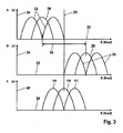
- Fig. 3 AC graphically show the formation of the directional amplitude functions.
- Fig. 3 A and Fig. 3 B are from the directional diagram Fig. 2 derived.
- the reception angle ⁇ in degrees is plotted on a horizontal axis 22 and on a vertical axis 24, the normalized antenna output voltage U / U 0 in volts. Shown are also the main lobes 26, 28 of the previously determined directional characteristics.
- Fig. 3 A and Fig. 3 B illustrate the scanning of the direction by an assumed signal direction 20.
- the direction of interest range 36 or angle range is located on both sides of the assumed signal direction 20 and preferably comprises an extension corresponding to a double main lobe width.
- This predetermined directional range 36 is scanned sequentially by means of the main lobes 26, 28 of the directional characteristics in small angular steps. The result of this sampling are three measured, direction-dependent amplitude functions FA, FB, FC, which in Fig. 3C are shown.
- Fig. 3 A and 3 B be in Fig. 3C on the horizontal axis 38, the receiving angle ⁇ plotted in degrees.
- the vertical axis 40 indicates the measured amplitude in volts.
- the invention is not limited to such a sequential formation of the directional amplitude functions FA, FB, FC.
- Alternative methods for forming the direction-dependent amplitude functions FA, FB, FC are conceivable.
- the three direction-dependent amplitude functions FA, FB, FC are arranged such that the maximum of the central amplitude function FB and the assumed signal direction 20 are at the same angle. They will according to Fig. 1 a calculation unit 42 passed to determine a sum function FS by adding the two direction-dependent amplitude functions FA and FC. This sum function FS is in turn passed to a differential element 44 for determining the second derivative. This differentiation is described in detail by the illustrations in Fig. 4 AB and Fig. 5 explained in more detail.
- Fig. 4 A shows a graphical representation of the sum function FS and Fig. 4B both the first derivative 48 and the second derivative 50.
- the reception angles ⁇ are plotted in degrees, and on the vertical axes 40 the amplitudes in volts.
- the sum function FS is a function of the amplitude over the receiving angle ⁇
- its derivatives 48, 50 are derivatives of the angle ⁇ and of the location, respectively.
- the second derivative 50 of the summation function FS describes the change in that quantity which is determined by the first derivative 48.
- the second derivative 50 provides information about the curvature behavior of the sum function FS.
- the directional characteristics of the resulting direction-dependent amplitude functions FA, FB, FC are arranged such that the central amplitude function FB has its maximum at the level of the assumed signal direction 20 and consequently the sum function FS has a minimum at this point.
- the second derivative 50 of the summation function FS receives a local maximum in the assumed signal direction 20.
- the reception angle ⁇ is plotted in degrees with the assumed signal direction 20 at 0 degrees.
- the amplitude is plotted in volts.
- the sum function FS can also be recognized as a dashed line.
- the second derivative 50 of the summation function FS is shown as a solid line in the directional diagram. There are fifteen local maxima 56 of the second derivative 50 recognizable. The angle values ⁇ of the local maxima 56 correspond to the possible, potential signal directions of the received sound waves.
- the central amplitude function FB is first checked whether there is a significant signal amplitude of the incident sound waves in these potential, potential signal directions. If the signals of the possible, potential signal directions have a sufficient signal amplitude, these are stored, for example, as i potential signal directions z i and according to Fig. 1 passed to another calculation unit 58.
- This further calculation unit 58 Fig. 1 determined for each potential direction signal z i is an amplitude function Z i.
- the central directional characteristic of the direction generator 16 is used.
- the amplitude function Z i is calculated via the central directional characteristic direction range 36 on the assumption that an acoustic wave front would come from this direction.
- these amplitude functions Z i are normalized to a maximum value, for example 1.
- the thus determined amplitude functions Z 1 , Z 2 ,..., Z i are passed to an analysis unit 60 in order to determine the actual signal directions therefrom. Furthermore, this analysis unit 60 receives the central direction-dependent amplitude function FB of the measuring device 34.
- the analysis unit 60 determines the dependence of a target variable on one or more output variables by means of a statistical analysis method.
- the multiple linear regression is used as a statistical analysis method.
- further alternative analysis methods is conceivable.
- the multiple linear regression allows the detection of an influence of several explanatory quantities on a target size.
- the dependencies between the potential signal directions z i and the central direction-dependent amplitude function FB are determined.
- Fig. 6 shows the result of multiple linear regression.
- the calculated amplitude Z i is shown that z i-inverted to each share this single direction on the measured direction-dependent amplitude function FB represents.
- the reception angle ⁇ in degrees is plotted on the horizontal axis 62 and the amplitude in volts on the vertical axis 64.
- the exemplified amplitudes Z 1 , Z 2 ,..., Z 15 of the potential signal directions Z 1 , Z 2 ,..., Z 15 correspond to the previously determined local maxima 56 Fig. 5 ,
- the potential signal directions z 6 , z 7 , z 8 , z 9 and z 10 correspond to the actual signal directions.
- the results of the multiple linear regression are thus both the actual signal directions and the associated signal strengths of the sound-emitting targets or objects. They may be so close to each other that their radiated noise or sound waves are directionally within the main lobe of a directional characteristic and are received simultaneously. However, if the signals of the sound-emitting targets come from a directional continuum, an application of the method is not possible.
- a DC component 66 or an offset is shown, which also results from the multiple linear regression.
- This possibly existing DC component is produced, for example, by noise components in the signals.
- the multiple linear regression provides a standard deviation as a measure of the goodness of the match.
- the method according to the invention is applied at short intervals. This results in a substantially continuous application, which provides a statistical evaluation regarding the uniqueness of the measurement results. Furthermore, by the substantially continuous application of the method, a dynamic detection of changes in direction of the sound-emitting targets is possible.
Landscapes
- Physics & Mathematics (AREA)
- Engineering & Computer Science (AREA)
- General Physics & Mathematics (AREA)
- Radar, Positioning & Navigation (AREA)
- Remote Sensing (AREA)
- Measurement Of Velocity Or Position Using Acoustic Or Ultrasonic Waves (AREA)
Claims (10)
- Procédé de localisation de cibles à émissions sonores au moyen d'une antenne de réception (10) comportant une pluralité de transducteurs électroacoustiques ou optoacoustiques (12) pour la réception d'ondes sonores se propageant dans l'eau et la production de signaux de réception électriques (14), dans lequel, pour la génération de signaux de réception en phase, des coefficients de temporisation sont appliqués aux signaux de réception (14) et les signaux de réception en phase (14) sont additionnés pour former des signaux de groupe qui sont fournis à un générateur de direction (16) pour la génération d'au moins trois caractéristiques de directivité décalées les unes par rapport aux autres, les coefficients de temporisation étant choisis, pour la production des caractéristiques de directivité, de telle manière qu'une caractéristique de directivité centrale soit produite avec un lobe principal (28) qui, dans une représentation imaginaire des caractéristiques de directivité dans un diagramme de directivité cartésien horizontal (Fig. 2) dans lequel la tension de sortie de l'antenne (U/U0) est tracée en fonction de l'angle de réception (ϑ) des ondes sonores, est chevauché sur les deux côtés par les lobes principaux (26) de caractéristiques de directivité adjacentes et ce, de telle manière que ces deux lobes principaux (26) se touchent ou se coupent à hauteur de l'angle de réception (ϑZ) au niveau duquel le lobe principal (28) de la caractéristique de directivité centrale présente son maximum (30),
caractérisé en ce que
au moins trois fonctions d'amplitude (FA, FB, FC) dépendantes de la direction sont générées au moyen des lobes principaux (26, 28) des caractéristiques de directivité générées et ce, selon des distances angulaires constantes prédéterminées sur une plage directionnelle (36) prédéterminée,
une fonction de somme (FS) est déterminée par addition des deux fonctions d'amplitude (FA, FC) dépendantes de la direction résultant des deux caractéristiques de directivité adjacentes, sur les deux côtés, à la caractéristique de directivité centrale,
la fonction de somme (FS) est différenciée deux fois pour déterminer sa dérivée seconde (50), la dérivée seconde (50) de la fonction de somme (FS) présentant des maxima locaux (56) qui correspondent aux directions de signal discrètes potentielles (zi) des ondes sonores reçues, et
les directions de signal réelles ainsi que les intensités de signal correspondantes sont déterminées à partir des directions de signal potentielles (zi) au moyen d'un procédé d'analyse statistique permettant d'établir des dépendances entre les directions de signal potentielles (zi) et une fonction d'amplitude centrale dépendante de la direction, notamment la régression linéaire multiple, moyennant quoi celles des directions de signal dont les parts à la fonction d'amplitude centrale dépendante de la direction (FB) dépassent une valeur prédéfinie sont déterminées comme étant les directions de signal réelles. - Procédé selon la revendication 1,
caractérisé en ce que
les fonctions d'amplitude (FA, FB, FC) dépendantes de la direction sont générées par orientation des caractéristiques de directivité sur une plage directionnelle (36) prédéterminée et par balayage de la plage directionnelle (36) selon des distances angulaires constantes prédéterminées. - Procédé selon la revendication 1,
caractérisé en ce que
les fonctions d'amplitude (FA, FB, FC) dépendantes de la direction sont générées par génération de direction simultanée des caractéristiques de directivité avec une distance angulaire identique prédéterminée sur une plage directionnelle (36) prédéterminée. - Procédé selon l'une des revendications précédentes,
caractérisé en ce que
le procédé d'analyse statistique correspond à la régression linéaire multiple et une composante continue est calculée et/ou un indice pour une qualité des résultats de mesure est fournie. - Procédé selon l'une des revendications précédentes,
caractérisé en ce que
la réitération multiple du procédé favorise une utilisation sensiblement continue, laquelle permet une évaluation statistique relativement à l'univocité des résultats de mesure et/ou une reconnaissance dynamique des modifications directionnelles des cibles à émissions sonores. - Dispositif de localisation de cibles à émissions sonores au moyen d'une antenne de réception (10) comportant une pluralité de transducteurs électroacoustiques ou optoacoustiques (12) pour la réception d'ondes sonores se propageant dans l'eau et la production de signaux de réception électriques (14), dans lequel, pour la génération de signaux de réception (14) en phase, des coefficients de temporisation peuvent être appliqués aux signaux de réception (14) et les signaux de réception (14) en phase peuvent être additionnés pour former des signaux de groupe qui peuvent être fournis à un générateur de direction (16) pour la génération d'au moins trois caractéristiques de directivité décalées les unes par rapport aux autres, les coefficients de temporisation pouvant être choisis, pour la production des caractéristiques de directivité, de telle manière qu'une caractéristique de directivité centrale puisse être produite avec un lobe principal (28) qui, dans une représentation imaginaire des caractéristiques de directivité dans un diagramme de directivité cartésien horizontal (Fig. 2), dans lequel la tension de sortie de l'antenne (U/U0) est tracée en fonction de l'angle de réception (ϑ) des ondes sonores, peut être chevauché sur les deux côtés par les lobes principaux (26) de caractéristiques de directivité adjacentes et ce, de telle manière que ces deux lobes principaux (26) se touchent ou se coupent à hauteur de l'angle de réception (ϑZ) au niveau duquel le lobe principal (28) de la caractéristique de directivité centrale présente son maximum (30),
caractérisé par
un dispositif de mesure (34) permettant de générer au moins trois fonctions d'amplitude (FA, FB, FC) dépendantes de la direction au moyen des lobes principaux (26, 28) des trois caractéristiques de directivité et ce, selon des distances angulaires constantes prédéterminées sur une plage directionnelle (36) prédéterminée,
une unité de calcul (42) permettant de déterminer une fonction de somme (FS) par addition des deux fonctions d'amplitude (FA, FC) dépendantes de la direction résultant des deux caractéristiques de directivité adjacentes, sur les deux côtés, à la caractéristique de directivité centrale,
la fonction de somme (FS) pouvant être différenciée deux fois, au moyen d'un élément différentiel (44), pour déterminer sa dérivée seconde (50) et la dérivée seconde (50) de la fonction de somme (FS) présentant des maxima locaux (56) qui correspondent aux directions de signal discrètes potentielles (zi) des ondes sonores reçues, et
une unité d'analyse (60) pour l'établissement des dépendances entre les directions de signal potentielles (zi) et une fonction d'amplitude centrale dépendante de la direction, celle-ci étant conçue pour déterminer, à partir des directions de signal potentielles (zi), des directions de signal réelles ainsi que les intensités de signal correspondantes, moyennant quoi celles des directions de signal dont les parts à la fonction d'amplitude centrale dépendante de la direction (FB) dépassent une valeur prédéfinie peuvent être déterminées comme étant les directions de signal réelles. - Dispositif selon la revendication 6,
caractérisé en ce que
les fonctions d'amplitude (FA, FB, FC) dépendantes de la direction peuvent être générées par orientation des caractéristiques de directivité sur une plage directionnelle (36) prédéterminée et par balayage de la plage directionnelle (36) selon des distances angulaires constantes prédéterminées. - Dispositif selon la revendication 6,
caractérisé en ce que
les fonctions d'amplitude (FA, FB, FC) dépendantes de la direction peuvent être générées par génération de direction simultanée des caractéristiques de directivité avec une distance angulaire identique prédéterminée sur une plage directionnelle (36) prédéterminée. - Dispositif selon l'une des revendications 6 à 8,
caractérisé en ce que
l'unité d'analyse (60) met en oeuvre, comme procédé d'analyse statistique, une régression linéaire multiple, laquelle calcule une composante continue et/ou un indice pour une qualité des résultats de mesure. - Dispositif selon l'une des revendications 6 à 9,
caractérisé en ce que
la réitération multiple du procédé peut favoriser une utilisation sensiblement continue, laquelle permet une évaluation statistique relativement à l'univocité des résultats de mesure et/ou une reconnaissance des modifications directionnelles dynamiques des cibles à émissions sonores.
Applications Claiming Priority (2)
| Application Number | Priority Date | Filing Date | Title |
|---|---|---|---|
| DE102009042967A DE102009042967A1 (de) | 2009-09-24 | 2009-09-24 | Verfahren und Vorrichtung zum Peilen von schallabstrahlenden Zielen |
| PCT/EP2010/062041 WO2011035995A1 (fr) | 2009-09-24 | 2010-08-18 | Procédé et dispositif de localisation de cibles émettant un rayonnement |
Publications (2)
| Publication Number | Publication Date |
|---|---|
| EP2480907A1 EP2480907A1 (fr) | 2012-08-01 |
| EP2480907B1 true EP2480907B1 (fr) | 2013-10-16 |
Family
ID=42829450
Family Applications (1)
| Application Number | Title | Priority Date | Filing Date |
|---|---|---|---|
| EP10742856.7A Not-in-force EP2480907B1 (fr) | 2009-09-24 | 2010-08-18 | Procédé et dispositif de localisation de cibles émettant un rayonnement |
Country Status (3)
| Country | Link |
|---|---|
| EP (1) | EP2480907B1 (fr) |
| DE (1) | DE102009042967A1 (fr) |
| WO (1) | WO2011035995A1 (fr) |
Families Citing this family (2)
| Publication number | Priority date | Publication date | Assignee | Title |
|---|---|---|---|---|
| DE102019201005B4 (de) | 2019-01-28 | 2023-11-23 | Atlas Elektronik Gmbh | Verfahren zum Festlegen von Haupt-Blickrichtungen einer Unterwasserantenne und Unterwasserantenne |
| CN112880622B (zh) * | 2021-02-04 | 2022-12-13 | 上海航天控制技术研究所 | 一种应用倾角仪标定柔性喷管摆角传感器的方法 |
Family Cites Families (2)
| Publication number | Priority date | Publication date | Assignee | Title |
|---|---|---|---|---|
| JP2630560B2 (ja) * | 1993-09-13 | 1997-07-16 | 宇宙開発事業団 | レーダにおけるアンテナパターンのビーム圧縮処理方法 |
| DE4442935A1 (de) | 1994-12-02 | 1996-06-13 | Stn Atlas Elektronik Gmbh | Verfahren zum Peilen schallabstrahlender oder schallreflektierender Ziele |
-
2009
- 2009-09-24 DE DE102009042967A patent/DE102009042967A1/de not_active Withdrawn
-
2010
- 2010-08-18 WO PCT/EP2010/062041 patent/WO2011035995A1/fr not_active Ceased
- 2010-08-18 EP EP10742856.7A patent/EP2480907B1/fr not_active Not-in-force
Also Published As
| Publication number | Publication date |
|---|---|
| WO2011035995A1 (fr) | 2011-03-31 |
| EP2480907A1 (fr) | 2012-08-01 |
| DE102009042967A1 (de) | 2011-04-07 |
Similar Documents
| Publication | Publication Date | Title |
|---|---|---|
| DE69218331T2 (de) | Rauschpegelverringerung in Radargeräten für Streuziele | |
| EP4196818B1 (fr) | Procédé et dispositif permettant de déterminer des perturbations de fréquence dans un signal reçu d'un système sar à canaux multiples actif | |
| DE10313331B4 (de) | Verfahren zur Bestimmung einer Einfallsrichtung eines Signals einer akustischen Signalquelle und Vorrichtung zur Durchführung des Verfahrens | |
| EP2005209B1 (fr) | Procédé et dispositif de saisie d'un ou de plusieurs objets dans l'environnement d'un véhicule à moteur | |
| EP2480907B1 (fr) | Procédé et dispositif de localisation de cibles émettant un rayonnement | |
| EP2589977B1 (fr) | Procédé et dispositif de correction d'une erreur de relèvement systématique | |
| DE19648327B4 (de) | Verfahren zur Richtstrahlbildung in Peilanlagen und Vorrichtung zur Durchführung des Verfahrens | |
| EP2480910B1 (fr) | Procédé et dispositif de mesure du profil du sol | |
| EP1134592A1 (fr) | Filtre STAP temps réel pour suppression de cible fixe | |
| DE102010056526B4 (de) | Verfahren zum Bestimmen einer oder mehrerer relativer Richtungen als Zielpeilung oder Zielpeilungen sowie Vorrichtung zur Ausführung des Verfahrens | |
| DE102022201395B4 (de) | Ermitteln einer Ursprungsrichtung von Schallsignalen | |
| EP2333574B1 (fr) | Procédé d'amélioration de l'exactitude de mesure, dispositif d'amélioration de l'exactitude de mesure et installation sonar | |
| DE10332886B3 (de) | Verfahren zum Bestimmen von Zieldaten mit einer Aktiv-Sonaranlage | |
| DE102017100909B4 (de) | Schätzung eines Einfallswinkels | |
| WO2021213843A1 (fr) | Procédé associé à un radar et système radar d'analyse à cohérence de phase | |
| DE10153443C1 (de) | Verfahren zur passiven Ortung von schallabstrahlenden Zielen | |
| EP1176428B1 (fr) | Procede pour ameliorer le rapport signal sur bruit d'un réseau d'antennes sonar | |
| EP1307761B1 (fr) | Procede de localisation de direction et dispositif de localisation | |
| DE10153444C1 (de) | Verfahren zur passiven Ortung von schallabstrahlenden Zielen | |
| DE102009047941B3 (de) | Verfahren zur akustischen Vermessung eines Gewässergrundes sowie Fächerloteinrichtung | |
| EP1281982B1 (fr) | Procédé et circuit d'évaluation de la cohérence des ondes acoustiques | |
| WO2023152077A1 (fr) | Système de microphone et produit-programme d'ordinateur pour déterminer une direction d'origine de signaux sonores et véhicule équipé d'un tel système de microphone | |
| EP4553529A1 (fr) | Détermination optimisée de l'angle d'arrivée (aoa) | |
| EP0962784A2 (fr) | Procédé passif de détermination de données de cibles | |
| EP4258021A1 (fr) | Procédé et dispositif d'examen de l'environnement d'un véhicule au moyen des signaux ultrasonores |
Legal Events
| Date | Code | Title | Description |
|---|---|---|---|
| PUAI | Public reference made under article 153(3) epc to a published international application that has entered the european phase |
Free format text: ORIGINAL CODE: 0009012 |
|
| 17P | Request for examination filed |
Effective date: 20120320 |
|
| AK | Designated contracting states |
Kind code of ref document: A1 Designated state(s): AL AT BE BG CH CY CZ DE DK EE ES FI FR GB GR HR HU IE IS IT LI LT LU LV MC MK MT NL NO PL PT RO SE SI SK SM TR |
|
| DAX | Request for extension of the european patent (deleted) | ||
| 17Q | First examination report despatched |
Effective date: 20130222 |
|
| GRAP | Despatch of communication of intention to grant a patent |
Free format text: ORIGINAL CODE: EPIDOSNIGR1 |
|
| GRAS | Grant fee paid |
Free format text: ORIGINAL CODE: EPIDOSNIGR3 |
|
| GRAA | (expected) grant |
Free format text: ORIGINAL CODE: 0009210 |
|
| AK | Designated contracting states |
Kind code of ref document: B1 Designated state(s): AL AT BE BG CH CY CZ DE DK EE ES FI FR GB GR HR HU IE IS IT LI LT LU LV MC MK MT NL NO PL PT RO SE SI SK SM TR |
|
| REG | Reference to a national code |
Ref country code: GB Ref legal event code: FG4D Free format text: NOT ENGLISH |
|
| REG | Reference to a national code |
Ref country code: CH Ref legal event code: EP |
|
| REG | Reference to a national code |
Ref country code: IE Ref legal event code: FG4D Free format text: LANGUAGE OF EP DOCUMENT: GERMAN |
|
| REG | Reference to a national code |
Ref country code: AT Ref legal event code: REF Ref document number: 636752 Country of ref document: AT Kind code of ref document: T Effective date: 20131115 |
|
| REG | Reference to a national code |
Ref country code: DE Ref legal event code: R096 Ref document number: 502010005092 Country of ref document: DE Effective date: 20131212 |
|
| REG | Reference to a national code |
Ref country code: NL Ref legal event code: VDEP Effective date: 20131016 |
|
| REG | Reference to a national code |
Ref country code: LT Ref legal event code: MG4D |
|
| PG25 | Lapsed in a contracting state [announced via postgrant information from national office to epo] |
Ref country code: NL Free format text: LAPSE BECAUSE OF FAILURE TO SUBMIT A TRANSLATION OF THE DESCRIPTION OR TO PAY THE FEE WITHIN THE PRESCRIBED TIME-LIMIT Effective date: 20131016 Ref country code: SE Free format text: LAPSE BECAUSE OF FAILURE TO SUBMIT A TRANSLATION OF THE DESCRIPTION OR TO PAY THE FEE WITHIN THE PRESCRIBED TIME-LIMIT Effective date: 20131016 Ref country code: LT Free format text: LAPSE BECAUSE OF FAILURE TO SUBMIT A TRANSLATION OF THE DESCRIPTION OR TO PAY THE FEE WITHIN THE PRESCRIBED TIME-LIMIT Effective date: 20131016 Ref country code: IS Free format text: LAPSE BECAUSE OF FAILURE TO SUBMIT A TRANSLATION OF THE DESCRIPTION OR TO PAY THE FEE WITHIN THE PRESCRIBED TIME-LIMIT Effective date: 20140216 Ref country code: FI Free format text: LAPSE BECAUSE OF FAILURE TO SUBMIT A TRANSLATION OF THE DESCRIPTION OR TO PAY THE FEE WITHIN THE PRESCRIBED TIME-LIMIT Effective date: 20131016 Ref country code: NO Free format text: LAPSE BECAUSE OF FAILURE TO SUBMIT A TRANSLATION OF THE DESCRIPTION OR TO PAY THE FEE WITHIN THE PRESCRIBED TIME-LIMIT Effective date: 20140116 Ref country code: HR Free format text: LAPSE BECAUSE OF FAILURE TO SUBMIT A TRANSLATION OF THE DESCRIPTION OR TO PAY THE FEE WITHIN THE PRESCRIBED TIME-LIMIT Effective date: 20131016 |
|
| PG25 | Lapsed in a contracting state [announced via postgrant information from national office to epo] |
Ref country code: LV Free format text: LAPSE BECAUSE OF FAILURE TO SUBMIT A TRANSLATION OF THE DESCRIPTION OR TO PAY THE FEE WITHIN THE PRESCRIBED TIME-LIMIT Effective date: 20131016 Ref country code: CY Free format text: LAPSE BECAUSE OF FAILURE TO SUBMIT A TRANSLATION OF THE DESCRIPTION OR TO PAY THE FEE WITHIN THE PRESCRIBED TIME-LIMIT Effective date: 20131016 Ref country code: ES Free format text: LAPSE BECAUSE OF FAILURE TO SUBMIT A TRANSLATION OF THE DESCRIPTION OR TO PAY THE FEE WITHIN THE PRESCRIBED TIME-LIMIT Effective date: 20131016 |
|
| PG25 | Lapsed in a contracting state [announced via postgrant information from national office to epo] |
Ref country code: PT Free format text: LAPSE BECAUSE OF FAILURE TO SUBMIT A TRANSLATION OF THE DESCRIPTION OR TO PAY THE FEE WITHIN THE PRESCRIBED TIME-LIMIT Effective date: 20140217 |
|
| REG | Reference to a national code |
Ref country code: DE Ref legal event code: R097 Ref document number: 502010005092 Country of ref document: DE |
|
| PG25 | Lapsed in a contracting state [announced via postgrant information from national office to epo] |
Ref country code: EE Free format text: LAPSE BECAUSE OF FAILURE TO SUBMIT A TRANSLATION OF THE DESCRIPTION OR TO PAY THE FEE WITHIN THE PRESCRIBED TIME-LIMIT Effective date: 20131016 |
|
| PLBE | No opposition filed within time limit |
Free format text: ORIGINAL CODE: 0009261 |
|
| STAA | Information on the status of an ep patent application or granted ep patent |
Free format text: STATUS: NO OPPOSITION FILED WITHIN TIME LIMIT |
|
| PG25 | Lapsed in a contracting state [announced via postgrant information from national office to epo] |
Ref country code: CZ Free format text: LAPSE BECAUSE OF FAILURE TO SUBMIT A TRANSLATION OF THE DESCRIPTION OR TO PAY THE FEE WITHIN THE PRESCRIBED TIME-LIMIT Effective date: 20131016 Ref country code: RO Free format text: LAPSE BECAUSE OF FAILURE TO SUBMIT A TRANSLATION OF THE DESCRIPTION OR TO PAY THE FEE WITHIN THE PRESCRIBED TIME-LIMIT Effective date: 20131016 Ref country code: SK Free format text: LAPSE BECAUSE OF FAILURE TO SUBMIT A TRANSLATION OF THE DESCRIPTION OR TO PAY THE FEE WITHIN THE PRESCRIBED TIME-LIMIT Effective date: 20131016 Ref country code: PL Free format text: LAPSE BECAUSE OF FAILURE TO SUBMIT A TRANSLATION OF THE DESCRIPTION OR TO PAY THE FEE WITHIN THE PRESCRIBED TIME-LIMIT Effective date: 20131016 Ref country code: IT Free format text: LAPSE BECAUSE OF FAILURE TO SUBMIT A TRANSLATION OF THE DESCRIPTION OR TO PAY THE FEE WITHIN THE PRESCRIBED TIME-LIMIT Effective date: 20131016 |
|
| 26N | No opposition filed |
Effective date: 20140717 |
|
| PG25 | Lapsed in a contracting state [announced via postgrant information from national office to epo] |
Ref country code: DK Free format text: LAPSE BECAUSE OF FAILURE TO SUBMIT A TRANSLATION OF THE DESCRIPTION OR TO PAY THE FEE WITHIN THE PRESCRIBED TIME-LIMIT Effective date: 20131016 |
|
| REG | Reference to a national code |
Ref country code: DE Ref legal event code: R097 Ref document number: 502010005092 Country of ref document: DE Effective date: 20140717 |
|
| PG25 | Lapsed in a contracting state [announced via postgrant information from national office to epo] |
Ref country code: SI Free format text: LAPSE BECAUSE OF FAILURE TO SUBMIT A TRANSLATION OF THE DESCRIPTION OR TO PAY THE FEE WITHIN THE PRESCRIBED TIME-LIMIT Effective date: 20131016 |
|
| PG25 | Lapsed in a contracting state [announced via postgrant information from national office to epo] |
Ref country code: LU Free format text: LAPSE BECAUSE OF FAILURE TO SUBMIT A TRANSLATION OF THE DESCRIPTION OR TO PAY THE FEE WITHIN THE PRESCRIBED TIME-LIMIT Effective date: 20140818 Ref country code: MC Free format text: LAPSE BECAUSE OF FAILURE TO SUBMIT A TRANSLATION OF THE DESCRIPTION OR TO PAY THE FEE WITHIN THE PRESCRIBED TIME-LIMIT Effective date: 20131016 |
|
| REG | Reference to a national code |
Ref country code: CH Ref legal event code: PL |
|
| PG25 | Lapsed in a contracting state [announced via postgrant information from national office to epo] |
Ref country code: BE Free format text: LAPSE BECAUSE OF NON-PAYMENT OF DUE FEES Effective date: 20140831 Ref country code: CH Free format text: LAPSE BECAUSE OF NON-PAYMENT OF DUE FEES Effective date: 20140831 Ref country code: LI Free format text: LAPSE BECAUSE OF NON-PAYMENT OF DUE FEES Effective date: 20140831 |
|
| REG | Reference to a national code |
Ref country code: IE Ref legal event code: MM4A |
|
| PG25 | Lapsed in a contracting state [announced via postgrant information from national office to epo] |
Ref country code: IE Free format text: LAPSE BECAUSE OF NON-PAYMENT OF DUE FEES Effective date: 20140818 |
|
| PG25 | Lapsed in a contracting state [announced via postgrant information from national office to epo] |
Ref country code: SM Free format text: LAPSE BECAUSE OF FAILURE TO SUBMIT A TRANSLATION OF THE DESCRIPTION OR TO PAY THE FEE WITHIN THE PRESCRIBED TIME-LIMIT Effective date: 20131016 |
|
| PG25 | Lapsed in a contracting state [announced via postgrant information from national office to epo] |
Ref country code: MT Free format text: LAPSE BECAUSE OF FAILURE TO SUBMIT A TRANSLATION OF THE DESCRIPTION OR TO PAY THE FEE WITHIN THE PRESCRIBED TIME-LIMIT Effective date: 20131016 Ref country code: BG Free format text: LAPSE BECAUSE OF FAILURE TO SUBMIT A TRANSLATION OF THE DESCRIPTION OR TO PAY THE FEE WITHIN THE PRESCRIBED TIME-LIMIT Effective date: 20131016 Ref country code: GR Free format text: LAPSE BECAUSE OF FAILURE TO SUBMIT A TRANSLATION OF THE DESCRIPTION OR TO PAY THE FEE WITHIN THE PRESCRIBED TIME-LIMIT Effective date: 20140117 |
|
| PG25 | Lapsed in a contracting state [announced via postgrant information from national office to epo] |
Ref country code: TR Free format text: LAPSE BECAUSE OF FAILURE TO SUBMIT A TRANSLATION OF THE DESCRIPTION OR TO PAY THE FEE WITHIN THE PRESCRIBED TIME-LIMIT Effective date: 20131016 Ref country code: HU Free format text: LAPSE BECAUSE OF FAILURE TO SUBMIT A TRANSLATION OF THE DESCRIPTION OR TO PAY THE FEE WITHIN THE PRESCRIBED TIME-LIMIT; INVALID AB INITIO Effective date: 20100818 |
|
| REG | Reference to a national code |
Ref country code: FR Ref legal event code: PLFP Year of fee payment: 7 |
|
| REG | Reference to a national code |
Ref country code: AT Ref legal event code: MM01 Ref document number: 636752 Country of ref document: AT Kind code of ref document: T Effective date: 20150818 |
|
| PG25 | Lapsed in a contracting state [announced via postgrant information from national office to epo] |
Ref country code: AT Free format text: LAPSE BECAUSE OF NON-PAYMENT OF DUE FEES Effective date: 20150818 |
|
| REG | Reference to a national code |
Ref country code: FR Ref legal event code: PLFP Year of fee payment: 8 |
|
| PG25 | Lapsed in a contracting state [announced via postgrant information from national office to epo] |
Ref country code: MK Free format text: LAPSE BECAUSE OF FAILURE TO SUBMIT A TRANSLATION OF THE DESCRIPTION OR TO PAY THE FEE WITHIN THE PRESCRIBED TIME-LIMIT Effective date: 20131016 |
|
| REG | Reference to a national code |
Ref country code: FR Ref legal event code: PLFP Year of fee payment: 9 |
|
| PG25 | Lapsed in a contracting state [announced via postgrant information from national office to epo] |
Ref country code: AL Free format text: LAPSE BECAUSE OF FAILURE TO SUBMIT A TRANSLATION OF THE DESCRIPTION OR TO PAY THE FEE WITHIN THE PRESCRIBED TIME-LIMIT Effective date: 20131016 |
|
| PGFP | Annual fee paid to national office [announced via postgrant information from national office to epo] |
Ref country code: DE Payment date: 20200819 Year of fee payment: 11 Ref country code: FR Payment date: 20200821 Year of fee payment: 11 Ref country code: GB Payment date: 20200826 Year of fee payment: 11 |
|
| REG | Reference to a national code |
Ref country code: DE Ref legal event code: R119 Ref document number: 502010005092 Country of ref document: DE |
|
| GBPC | Gb: european patent ceased through non-payment of renewal fee |
Effective date: 20210818 |
|
| PG25 | Lapsed in a contracting state [announced via postgrant information from national office to epo] |
Ref country code: GB Free format text: LAPSE BECAUSE OF NON-PAYMENT OF DUE FEES Effective date: 20210818 Ref country code: FR Free format text: LAPSE BECAUSE OF NON-PAYMENT OF DUE FEES Effective date: 20210831 Ref country code: DE Free format text: LAPSE BECAUSE OF NON-PAYMENT OF DUE FEES Effective date: 20220301 |