EP1535697A1 - Procede et dispositif de traitement de l'interieur d'un materiau transparent - Google Patents
Procede et dispositif de traitement de l'interieur d'un materiau transparent Download PDFInfo
- Publication number
- EP1535697A1 EP1535697A1 EP03755268A EP03755268A EP1535697A1 EP 1535697 A1 EP1535697 A1 EP 1535697A1 EP 03755268 A EP03755268 A EP 03755268A EP 03755268 A EP03755268 A EP 03755268A EP 1535697 A1 EP1535697 A1 EP 1535697A1
- Authority
- EP
- European Patent Office
- Prior art keywords
- laser light
- shape
- femtosecond laser
- transparent material
- cross
- Prior art date
- Legal status (The legal status is an assumption and is not a legal conclusion. Google has not performed a legal analysis and makes no representation as to the accuracy of the status listed.)
- Withdrawn
Links
Images


Classifications
-
- C—CHEMISTRY; METALLURGY
- C03—GLASS; MINERAL OR SLAG WOOL
- C03C—CHEMICAL COMPOSITION OF GLASSES, GLAZES OR VITREOUS ENAMELS; SURFACE TREATMENT OF GLASS; SURFACE TREATMENT OF FIBRES OR FILAMENTS MADE FROM GLASS, MINERALS OR SLAGS; JOINING GLASS TO GLASS OR OTHER MATERIALS
- C03C23/00—Other surface treatment of glass not in the form of fibres or filaments
- C03C23/0005—Other surface treatment of glass not in the form of fibres or filaments by irradiation
- C03C23/0025—Other surface treatment of glass not in the form of fibres or filaments by irradiation by a laser beam
-
- B—PERFORMING OPERATIONS; TRANSPORTING
- B23—MACHINE TOOLS; METAL-WORKING NOT OTHERWISE PROVIDED FOR
- B23K—SOLDERING OR UNSOLDERING; WELDING; CLADDING OR PLATING BY SOLDERING OR WELDING; CUTTING BY APPLYING HEAT LOCALLY, e.g. FLAME CUTTING; WORKING BY LASER BEAM
- B23K26/00—Working by laser beam, e.g. welding, cutting or boring
- B23K26/02—Positioning or observing the workpiece, e.g. with respect to the point of impact; Aligning, aiming or focusing the laser beam
- B23K26/06—Shaping the laser beam, e.g. by masks or multi-focusing
- B23K26/062—Shaping the laser beam, e.g. by masks or multi-focusing by direct control of the laser beam
- B23K26/0622—Shaping the laser beam, e.g. by masks or multi-focusing by direct control of the laser beam by shaping pulses
- B23K26/0624—Shaping the laser beam, e.g. by masks or multi-focusing by direct control of the laser beam by shaping pulses using ultrashort pulses, i.e. pulses of 1 ns or less
-
- B—PERFORMING OPERATIONS; TRANSPORTING
- B23—MACHINE TOOLS; METAL-WORKING NOT OTHERWISE PROVIDED FOR
- B23K—SOLDERING OR UNSOLDERING; WELDING; CLADDING OR PLATING BY SOLDERING OR WELDING; CUTTING BY APPLYING HEAT LOCALLY, e.g. FLAME CUTTING; WORKING BY LASER BEAM
- B23K26/00—Working by laser beam, e.g. welding, cutting or boring
- B23K26/02—Positioning or observing the workpiece, e.g. with respect to the point of impact; Aligning, aiming or focusing the laser beam
- B23K26/06—Shaping the laser beam, e.g. by masks or multi-focusing
- B23K26/064—Shaping the laser beam, e.g. by masks or multi-focusing by means of optical elements, e.g. lenses, mirrors or prisms
- B23K26/066—Shaping the laser beam, e.g. by masks or multi-focusing by means of optical elements, e.g. lenses, mirrors or prisms by using masks
-
- B—PERFORMING OPERATIONS; TRANSPORTING
- B23—MACHINE TOOLS; METAL-WORKING NOT OTHERWISE PROVIDED FOR
- B23K—SOLDERING OR UNSOLDERING; WELDING; CLADDING OR PLATING BY SOLDERING OR WELDING; CUTTING BY APPLYING HEAT LOCALLY, e.g. FLAME CUTTING; WORKING BY LASER BEAM
- B23K26/00—Working by laser beam, e.g. welding, cutting or boring
- B23K26/50—Working by transmitting the laser beam through or within the workpiece
- B23K26/53—Working by transmitting the laser beam through or within the workpiece for modifying or reforming the material inside the workpiece, e.g. for producing break initiation cracks
-
- B—PERFORMING OPERATIONS; TRANSPORTING
- B23—MACHINE TOOLS; METAL-WORKING NOT OTHERWISE PROVIDED FOR
- B23K—SOLDERING OR UNSOLDERING; WELDING; CLADDING OR PLATING BY SOLDERING OR WELDING; CUTTING BY APPLYING HEAT LOCALLY, e.g. FLAME CUTTING; WORKING BY LASER BEAM
- B23K26/00—Working by laser beam, e.g. welding, cutting or boring
- B23K26/50—Working by transmitting the laser beam through or within the workpiece
- B23K26/55—Working by transmitting the laser beam through or within the workpiece for creating voids inside the workpiece, e.g. for forming flow passages or flow patterns
-
- C—CHEMISTRY; METALLURGY
- C03—GLASS; MINERAL OR SLAG WOOL
- C03C—CHEMICAL COMPOSITION OF GLASSES, GLAZES OR VITREOUS ENAMELS; SURFACE TREATMENT OF GLASS; SURFACE TREATMENT OF FIBRES OR FILAMENTS MADE FROM GLASS, MINERALS OR SLAGS; JOINING GLASS TO GLASS OR OTHER MATERIALS
- C03C4/00—Compositions for glass with special properties
- C03C4/04—Compositions for glass with special properties for photosensitive glass
Definitions
- the present invention relates to a method and a device for processing the inside of a transparent material, more specifically to a method and a device for processing the inside of a transparent material, which is preferably used in performing processing such as modification and working of the inside of the transparent material with respect to laser light of femtosecond laser light having the pulse width of a 10 -13 second order.
- femtosecond laser light which has the pulse width of a 10 -13 second order as a laser light source of a sub-picosecond or less.
- femtosecond laser light being laser light that is emitted from such femtosecond laser, which is a femtosecond laser having the pulse width of about 100 to 150 femtoseconds
- laser light that is emitted from femtosecond laser shall be referred to as "femtosecond laser light” in this specification
- femtosecond laser light is focused on the inside of a transparent material with respect to the femtosecond laser light (a transparent material with respect to predetermined femtosecond laser light shall be appropriately referred to simply as a "transparent material” in this specification) via a lens
- a transparent material with respect to predetermined femtosecond laser light shall be appropriately referred to simply as a "transparent material” in this specification
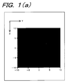
- the spatial intensity distribution in the direction parallel to the advance direction of the beam of femtosecond laser light at the focal spot should be the intensity distribution of a lengthwise elliptical shape extending in the advance direction of the beam of femtosecond laser light, as shown in Fig. 1(a).
- the processed shape such as a modified shape and a worked shape inside the transparent material became the lengthwise elliptical shape extending in the advance direction of the beam of femtosecond laser light by suffering from the spatial intensity distribution in the direction parallel to the advance direction of the beam of femtosecond laser light at the focal spot inside the transparent material.
- the processed shape such as a modified shape and a worked shape inside the transparent material became the lengthwise elliptical shape extending in the advance direction of the beam of femtosecond laser light when industrial fabrication and usage of micro-channel or optical waveguide are taken in consideration.
- the processed shape such as a modified shape and a worked shape inside the transparent material a shape whose cross-sectional shape in the direction parallel to the advance direction of the beam of femtosecond laser light is a substantially perfect circle was required.
- the spatial intensity distribution in the direction parallel to the advance direction of the beam of femtosecond laser light should be a shape of a substantially perfect circle.
- a shape whose cross-sectional shape in the direction parallel to the advance direction of the beam of femtosecond laser light is a substantially perfect circle as the processed shape such as a modified shape and a worked shape inside the transparent material while obtaining the spatial intensity distribution of a substantially perfect circle in the direction parallel to the advance direction of the beam of femtosecond laser light
- the use of an objective lens having a large numerical aperture is considered.
- a working distance (the working distance is the distance between the objective lens and a sample that is the transparent material to be modified or worked) becomes several hundred ⁇ m or less (the working distance is 200 to 300 ⁇ m when the femtosecond laser light is focused on the inside of the transparent material using an objective lens having the numerical aperture of 1), so that a problem was pointed out that the processing such as the modification and the working with respect to a region at a deep position inside the transparent material was impossible.
- the present invention has been created in view of the above-described problems that prior art has, and it is an object of the present invention to provide a method and a device for processing the inside of a transparent material, which is capable of obtaining a cross-sectional shape in a direction parallel to the advance direction of the beam of femtosecond laser light is a substantially perfect circle as the processed shape such as a modified shape or a worked shape on a light focus position being a light focus position, even if the femtosecond laser light is focused on the inside of the transparent material using a condenser lens of a relatively small numerical aperture, by which the working distance of several mm or more can be secured.
- the present invention is a method in which a beam shape of a cross-section in a direction perpendicular to the advance direction of laser light beam, which has emitted from a femtosecond laser, is shaped in a predetermined shape, laser light whose beam shape of the cross-section in the direction perpendicular to the advance direction is shaped in the predetermined shape is allowed to enter a lens and the light is focused on the inside of a transparent material by the lens, and the inside of the transparent material is processed by the operation of the laser light that is focused on the inside of the transparent material.
- the present invention is a method in which the predetermined shape is an approximately rectangular shape.
- the present invention is a method in which the predetermined shape is an approximately cross shape.
- the present invention is a device that has a femtosecond laser that emits laser light, beam shape shaping means that shapes the beam shape of a cross-section in the direction perpendicular to the advance direction of laser light beam, which is emitted from the femtosecond laser, in a predetermined shape, and a lens into which the laser light, whose beam shape of the cross-section in the direction perpendicular to the advance direction has been shaped in the predetermined shape by the beam shape shaping means, is allowed to enter and which focuses the laser light on the inside of the transparent material, in which the inside of the transparent material is processed by the operation of the laser light that has been focused on the inside of the transparent material by the lens.
- the present invention is a device that further has moving means that relatively moves the light focus position of laser light, which is focused on the inside of the transparent material, with respect to the transparent material.
- the present invention is a device in which the beam shape shaping means includes a slit of an approximately rectangular shape through which laser light emitted from the femtosecond laser light passes, and shapes the beam shape of the cross-section in the direction perpendicular to the advance direction of the laser light beam, which has been emitted from the femtosecond laser, in an approximately rectangular shape.
- the present invention is a device in which the beam shape shaping means includes a slit of an approximately cross shape through which laser light emitted from the femtosecond laser light passes, and shapes the beam shape of the cross-section in the direction perpendicular to the advance direction of the laser light beam, which has been emitted from the femtosecond laser, in an approximately cross shape.
- the present invention is a device in which the beam shape shaping means is means where the first cylindrical lens and the second cylindrical lens are sequentially arranged in parallel, and shapes the beam shape of the cross-section in the direction perpendicular to the advance direction of the laser light beam, which has been emitted from the femtosecond laser, in an approximately rectangular shape.
- the spatial intensity distribution in the direction parallel to the advance direction of the beam of femtosecond laser light at the focal spot inside the transparent material is a substantially perfect circle, and consequently, a shape whose cross-sectional shape in the direction parallel to the advance direction of the beam of femtosecond laser light is a substantially perfect circle can be obtained.
- the beam shape of the cross-section in the direction perpendicular to the advance direction of the laser light beam emitted from the femtosecond laser is shaped in the predetermined shape, which is an approximately rectangular shape or an approximately cross shape, for example, and entered into the lens
- the spatial intensity distribution in the direction parallel to the advance direction of the beam of femtosecond laser light at the focal spot inside the transparent material becomes a substantially perfect circle due to diffraction effect.
- a shape whose cross-sectional shape in the direction parallel to the advance direction of the beam of femtosecond laser light is a substantially perfect circle can be obtained as the processed shape such as a modified shape and a worked shape on the inside of the transparent material.
- Fig. 2 is a conceptual constitution exemplary view of a processing device for the inside of a transparent material.
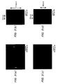
- Fig. 3(a), Fig. 3(b), Fig. 3(c), and Fig. 3(d) are micrographs of a micro-channel that has been experimentally fabricated by the inventors of this application. It is to be noted that Fig. 3(a) and Fig. 3(b) show a conventional case where the femtosecond laser light was directly focused by the objective lens and irradiated on the inside of a sample without using a slit member, and Fig. 3(c) and Fig. 3(d) show a case of the present invention where the femtosecond laser light was focused by the objective lens and irradiated on the inside of the sample after the light was allowed to pass through an approximately rectangular slit by using the slit member.
- Fig. 3(a) and Fig. 3(c) show results in which observation was made from the side surface of the sample, that is, from arrow A in Fig. 2, and Fig. 3(b) and Fig. 3(d) shows results in which the sample was mechanically cut off along B-B line in Fig. 2 from the top surface to the bottom surface and observation was made to a cross-section of a micro-channel, which is formed on the inside of the sample, in the direction perpendicular to the scanning direction of the beam of femtosecond laser light from arrow C.
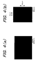
- Fig. 4(a) and Fig. 4(b) are micrographs of the micro-channel that has been experimentally fabricated by the inventors of this application.
- Fig. 4(a) shows a result in which observation was made from the side surface of the sample, that is, from arrow A in Fig. 2, and
- Fig. 4(b) shows a result in which the sample was mechanically cut off along B-B line in Fig. 2 from the top surface to the bottom surface and observation was made to a cross-section of a micro-channel, which is formed on the inside of the sample, in the direction perpendicular to the scanning direction of the beam of femtosecond laser light from arrow C.
- Fig. 5(a) and Fig. 5(b) are exemplary views showing other constitution examples of the slit member.
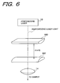
- Fig. 6 is an exemplary view showing a constitution example of beam shape shaping means that is different from the slit member.
- Fig. 2 shows the conceptual constitution exemplary view of the processing device for the inside of a transparent material according to the present invention.
- a sample 100 which is made of photosensitive glass as the transparent material
- the processing device of the inside of the transparent material according to the present invention is used, a case is shown for performing modification of a region that becomes a micro-channel 102 in order to form the micro-channel 102 inside the sample 100.
- Forturan glass can be used as the photosensitive glass, for example.
- the processing device for the inside of a transparent material shown in Fig. 2 is constituted by having a femtosecond laser 10 that irradiates femtosecond laser light having the pulse width of about 100 to 150 femtoseconds, for example, as the femtosecond laser light having the pulse width of a 10 -13 second order, a slit member 12 on which an approximately rectangular slit 12a is formed, through which the femtosecond laser light emitted from the femtosecond laser 10 passes, as the beam shape shaping means that shapes the beam shape of the cross-section in the direction perpendicular to the advance direction of laser light beam, which is emitted from the femtosecond laser 10, in a predetermined shape, and an objective lens 14 as a lens that focuses the femtosecond laser light, which has passed through the slit 12a of the slit member 12, on the inside of the sample 100.
- the processing device for the inside of a transparent material is provided with a moving table 200 as moving means that relatively moves the light focus position of the femtosecond laser light, which is focused on the inside of the sample 100 by the objective lens 14, with respect to the sample 100, and the sample 100 is mounted on the moving table 200.
- the moving table 200 is designed to be movable arbitrarily in X-direction, Y-direction and Z-direction in Fig. 2, and such movement is controlled by drive means (not shown) such as a motor.
- the processing device for the inside of a transparent material is aligned and fixed with respect to the sample 100, but is constituted such that the light focus position of the femtosecond laser light, which is focused on the inside of the sample 100, is arbitrarily moved in X-direction, Y-direction and Z-direction with respect to the sample 100 by arbitrarily moving the sample 100 in X-direction, Y-direction and Z-direction after mounting the sample on the moving table 200, and the femtosecond laser light is enabled to scan arbitrarily in X-direction, Y-direction and Z-direction inside the sample 100.
- the approximately rectangular slit 12a formed on the slit member 12 is formed so as to extend in X-direction where femtosecond laser light is allowed to scan relatively with respect to the sample 100, and its length L in a longitudinal direction is 3mm, for example, and length W in a width direction is 0.5mm, for example.
- a lens having the numerical aperture of 0.46 (magnification: ⁇ 20), for example, can be used as the objective lens 14.
- femtosecond laser light emitted from the femtosecond laser 10 passes through the slit 12a of the slit member 12, and is allowed to enter the objective lens 14 with a beam shape same as the shape of the slit 12a.
- the beam shape of the cross-section in the direction perpendicular to the advance direction of the beam of femtosecond laser light, which is emitted from the femtosecond laser 10 is shaped in an approximately rectangular shape when the femtosecond laser light passes through the slit 12a of the slit member 12, and femtosecond laser light, whose beam shape of the cross-section in the direction perpendicular to the advance direction of the beam is shaped in an approximately rectangular shape, is allowed to enter the objective lens 14.
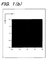
- the spatial intensity distribution in the direction parallel to the advance direction of the beam of femtosecond laser light at the focal spot is improved significantly according to the calculation result of the inventors of this application, and the spatial intensity distribution of a substantially perfect circle is obtained at the central portion of the focal spot as shown in Fig. 1(b)
- reference code P in Fig. 2 shows the shape of the focal spot of femtosecond laser light on X-Y plane in Fig. 2.
- the reason why the spatial intensity distribution was improved by the processing device for the inside of a transparent material according to the present invention is because the beam shape of femtosecond laser light was shaped in a long beam shape with respect to X-direction by the slit 12a, the diffraction effect occurred in this direction, and the beam spread in Y-direction at the point where the beam was focused by the objective lens 14 (the beam shape of femtosecond laser light at the focal spot matches the beam shape of femtosecond laser light that entered the objective lens 14, to which Fourier transformation was performed).
- the beam width in Y-direction increases when the beam shape of femtosecond laser light is shaped long with respect to X-direction
- a region to be processed by femtosecond laser light can be limited narrower since the spatial intensity at the central area of the light focus position is considerably weaker comparing to the case where the beam was not shaped.
- the width of a formed micro-channel is narrower when the beam was shaped despite that the beam width increased in Y-direction as shown in Figs. 3 and 4.
- a direction where the slit (shown by reference numeral 12a' in Fig. 5(a)) is positioned is rotated by 90 degrees from the direction of the slit 12a shown in Fig. 2 to shape the beam in a long beam shape in Y-direction
- a long beam shape in X-direction being a beam scanning direction is formed at the light focus position of femtosecond laser light, so that an even narrower channel can be fabricated.
- the experiment is for forming the micro-channel 102 inside the sample 100 made of photosensitive glass by using the processing device for the inside of a transparent material.
- femtosecond laser light is focused on the inside of the sample 100
- the sample 100 mounted on the moving table 200 is moved in X-direction by moving the moving table 200 in X-direction, and a flow path 102a of the micro-channel 102 is modified by scanning the femtosecond laser light in X-direction relatively with respect to the sample 100.
- the sample 100 mounted on the moving table is moved in Z-direction by moving the moving table 200 in Z-direction, and a flow path 102b of the micro-channel 102 is modified by scanning the femtosecond laser light in Z-direction relatively with respect to the sample 100. It is to be noted that the sample 100 is moved in Z-direction such that the focal spot of the femtosecond laser light is allowed to scan to the top surface 100a of the sample 100 in such occasion.
- the sample 100 mounted on the moving table 200 is moved in Z-direction by moving the moving table 200 in Z-direction, and a flow path 102c of the micro-channel 102 is modified by scanning the femtosecond laser light in Z-direction relatively with respect to the sample 100. It is to be noted that the sample 100 is moved in Z-direction such that the focal spot of the femtosecond laser light is allowed to scan to the top surface 100a of the sample 100 in such occasion.
- a region to which the femtosecond laser light was irradiated has etching rate on hydrofluoric acid solution several tens times to a region to which the femtosecond laser light was not irradiated. It is possible to selectively etch only the region to which the femtosecond laser light was irradiated by utilizing the difference of etching rate, and the micro-channel 102 was formed in a penetrated manner.
- Figs. 3(a), (b), (c) and (d) show the micrographs of the micro-channel 102 that was formed in the sample 100 as described above. It is to be noted that Figs. 3(a) and (b) show the conventional case where the femtosecond laser light was directly focused by the objective lens 14 and irradiated on the inside of the sample 100 without using the slit member 12, and Figs. 3(c) and (d) show the case of the present invention where the femtosecond laser light was focused by the objective lens 14 and irradiated on the inside of the sample 100 after the light was allowed to pass through the approximately rectangular slit 12a by using the slit member 12.
- Fig. 3(a) and (c) show the results in which observation was made from the side surface of the sample 100, that is, from arrow A in Fig. 2, and Fig. 3(b) and (d) show the results in which the sample 100 was mechanically cut off along B-B line in Fig. 2 from the top surface 100a to the bottom surface 100b and observation was made to the cross-section of the micro-channel 102, which was formed on the inside of the sample 100, in the direction perpendicular to the scanning direction of the beam of femtosecond laser light from arrow C.
- the length of the cross-sectional shape of the micro-channel 102 in a horizontal direction (width direction) is 40 ⁇ m for the one shown in Fig. 3(b) and 38 ⁇ m for the one shown in Fig. 3 (d), where the length when the slit 12 was used is slightly narrower.
- the length of the cross-sectional shape of the micro-channel 102 in a vertical direction is 119 ⁇ m for the one shown in Fig. 3(b) and 60 ⁇ m for the one shown in Fig. 3(d), where a large difference is between the both. Consequently, the aspect ratio that is the ratio of lengths in the vertical direction and the horizontal direction of the cross-sectional shape of the micro-channel 102 is "3" for the one shown in Fig. 3(b) and "1.6” for the one shown in Fig. 3(d), and thus the aspect ratio was improved significantly from “3" to "1.6” by allowing the femtosecond laser light to pass through the slit 12a.
- Figs. 4(a) and (b) show the results of experiment that was conducted under the completely same conditions as the experiment shown in Fig. 3 except that the size of the approximately rectangular slit 12a formed on the slit member 12 was set to 3mm for the length L in the longitudinal direction and 0.2mm for the length W in the width direction.
- Fig. 4(a) shows the result in which observation was made from the side surface of the sample 100, that is, from arrow A in Fig. 2
- Fig. 4(b) shows the result in which the sample 100 was mechanically cut off along B-B line in Fig.
- the aspect ratio is improved and the cross-sectional shape of the micro-channel 102 becomes a substantially perfect circle.
- the beam shape shaping means that shapes the beam shape of a cross-section in a direction perpendicular to the advance direction of laser light beam, which is emitted from a femtosecond laser, in a predetermined shape
- the slit member 12 was used, where the approximately rectangular slit 12a, through which the femtosecond laser light emitted from the femtosecond laser 10 passes, was formed along the X-direction in Fig. 2 out of the scanning directions of the femtosecond laser light.
- the invention is not limited to this.
- a slit member 12' (refer to Fig. 5(a)) may be used, where an approximately rectangular slit 12a, through which the femtosecond laser light emitted from the femtosecond laser 10 passes, is formed along the Y-direction perpendicular to the X-direction in Fig. 2 out of the scanning directions of the femtosecond laser light.
- a slit member 12 (refer to Fig. 5 (b)) on which a cross-shaped slit 12a" is formed may be used.
- an appropriate shape can be selected as the shape of the slit through which the femtosecond laser light emitted from the femtosecond laser 10 passes, and the arrangement position when arranging the slit with respect to the femtosecond laser light emitted from the femtosecond laser 10 can be appropriately selected.
- a narrower micro-channel can be formed as described above.
- the invention can be also applied not only for the fabrication of the micro-channel and the optical waveguide but also the micro-void, the three-dimensional memory, and the photonic crystal.
- the beam shape shaping means that shapes the beam shape of a cross-section in a direction perpendicular to the advance direction of laser light beam, which is emitted from a femtosecond laser, in a predetermined shape
- the slit member 12 was used, where the approximately rectangular slit 12a, through which the femtosecond laser light emitted from the femtosecond laser 10 passes, was formed along the scanning direction of the femtosecond laser light.
- the invention is not limited to this.
- the first cylindrical lens 300 having the focal distance of f1 and the second cylindrical lens 302 having the focal distance of f2 should be sequentially arranged between the femtosecond laser 10 and the objective lens 14 such that the lenses become perpendicular to the advance direction of the beam of femtosecond laser light emitted from the femtosecond laser 10 and extend parallelly with each other and in a same direction.
- the distance between the first cylindrical lens 300 and the second cylindrical lens 302 shall be "f1+f2".
- the beam shape of a cross-section in a direction perpendicular to the advance direction of laser light beam which was emitted from the femtosecond laser 10 and sequentially made incident to the first cylindrical lens 300 and the second cylindrical lens 302, becomes an approximately rectangular shape when it is emitted from the second cylindrical lens, and the femtosecond laser light, where the beam shape of a cross-section in a direction perpendicular to the advance direction of the beam is shaped in the approximately rectangular shape, enters the objective lens 14 and focused.
- the moving table 200 moved the sample 100 to relatively move the focal spot of femtosecond laser light with respect to the sample 100.
- the invention is not limited to this.
- the processing device for the inside of a transparent material is constituted to move with respect to the sample 100, and the constitution may be in such a manner that the focal spot of femtosecond laser light on the inside of the sample 100 is allowed to scan by moving the processing device for the inside of a transparent material.
- the present invention Since the present invention is constituted as described above, it exerts superior effect that a shape, whose cross-sectional shape in a direction parallel to the advance direction of the beam of femtosecond laser light, is a substantially perfect circle can be obtained as the processed shape such as a modified shape and a worked shape even if femtosecond laser light is focused on the inside of a transparent material by using a condenser lens having relatively small numerical aperture by which working distance of several mm or more can be secured.
Landscapes
- Optics & Photonics (AREA)
- Engineering & Computer Science (AREA)
- Physics & Mathematics (AREA)
- Chemical & Material Sciences (AREA)
- Mechanical Engineering (AREA)
- General Chemical & Material Sciences (AREA)
- Plasma & Fusion (AREA)
- Chemical Kinetics & Catalysis (AREA)
- Oil, Petroleum & Natural Gas (AREA)
- Life Sciences & Earth Sciences (AREA)
- Geochemistry & Mineralogy (AREA)
- Materials Engineering (AREA)
- Organic Chemistry (AREA)
- Health & Medical Sciences (AREA)
- Toxicology (AREA)
- Laser Beam Processing (AREA)
- Optical Integrated Circuits (AREA)
Applications Claiming Priority (3)
| Application Number | Priority Date | Filing Date | Title |
|---|---|---|---|
| JP2002149931A JP3559827B2 (ja) | 2002-05-24 | 2002-05-24 | 透明材料内部の処理方法およびその装置 |
| JP2002149931 | 2002-05-24 | ||
| PCT/JP2003/006039 WO2003099507A1 (fr) | 2002-05-24 | 2003-05-15 | Procede et dispositif de traitement de l'interieur d'un materiau transparent |
Publications (2)
| Publication Number | Publication Date |
|---|---|
| EP1535697A1 true EP1535697A1 (fr) | 2005-06-01 |
| EP1535697A4 EP1535697A4 (fr) | 2007-06-13 |
Family
ID=29561221
Family Applications (1)
| Application Number | Title | Priority Date | Filing Date |
|---|---|---|---|
| EP03755268A Withdrawn EP1535697A4 (fr) | 2002-05-24 | 2003-05-15 | Procede et dispositif de traitement de l'interieur d'un materiau transparent |
Country Status (4)
| Country | Link |
|---|---|
| US (1) | US7411151B2 (fr) |
| EP (1) | EP1535697A4 (fr) |
| JP (1) | JP3559827B2 (fr) |
| WO (1) | WO2003099507A1 (fr) |
Cited By (3)
| Publication number | Priority date | Publication date | Assignee | Title |
|---|---|---|---|---|
| WO2007033445A1 (fr) * | 2005-09-22 | 2007-03-29 | Trackinside, Société Anonyme | Dispositif et procede de marquage interne par laser |
| EP1964822A1 (fr) * | 2007-02-27 | 2008-09-03 | Cristales Curvados S.A. | Procédé de production de panneaux de verre décorés er panneaux de verre ainsi obtenus |
| CN103949772A (zh) * | 2014-04-22 | 2014-07-30 | 上海大学 | 飞秒激光在透明材料内制备三维可旋转纳米体光栅的方法 |
Families Citing this family (29)
| Publication number | Priority date | Publication date | Assignee | Title |
|---|---|---|---|---|
| WO2005033033A1 (fr) * | 2003-10-06 | 2005-04-14 | Hoya Corporation | Composant en verre presentant un orifice traversant et procede de production associe |
| DE102004037949B4 (de) * | 2004-08-05 | 2009-04-02 | Forschungszentrum Karlsruhe Gmbh | Verfahren zur Herstellung von Photonischen Kristallen |
| JP5002808B2 (ja) * | 2006-03-07 | 2012-08-15 | 国立大学法人北海道大学 | レーザ加工装置及びレーザ加工方法 |
| CA2622937A1 (fr) * | 2007-03-23 | 2008-09-23 | Nec Corporation | Corps marque et methode de fabrication connexe |
| US20090045179A1 (en) * | 2007-08-15 | 2009-02-19 | Ellen Marie Kosik Williams | Method and system for cutting solid materials using short pulsed laser |
| WO2011089592A1 (fr) * | 2010-01-20 | 2011-07-28 | Moshe Finarov | Procédé de traitement au laser |
| TWI426298B (zh) * | 2010-12-27 | 2014-02-11 | Univ Nat Taiwan Science Tech | 光學元件與雷射加工的方法 |
| JP5379172B2 (ja) * | 2011-01-11 | 2013-12-25 | 東山 亨 | フェムト秒レーザー加工機 |
| WO2012108316A1 (fr) * | 2011-02-08 | 2012-08-16 | 株式会社フジクラ | Procédé de fabrication d'un substrat ayant des micropores et substrat |
| JP5873488B2 (ja) * | 2011-05-25 | 2016-03-01 | 株式会社フジクラ | 微細孔を配した基体の製造方法、及び微細孔を配した基体 |
| EP2754524B1 (fr) | 2013-01-15 | 2015-11-25 | Corning Laser Technologies GmbH | Procédé et dispositif destinés au traitement basé sur laser de substrats plats, galette ou élément en verre, utilisant un faisceau laser en ligne |
| EP2781296B1 (fr) | 2013-03-21 | 2020-10-21 | Corning Laser Technologies GmbH | Dispositif et procédé de découpe de contours à partir de substrats plats au moyen d'un laser |
| JP6401248B2 (ja) * | 2013-05-15 | 2018-10-10 | コーニンクレッカ フィリップス エヌ ヴェKoninklijke Philips N.V. | 基板内に散乱機構を有するled |
| FR3006068B1 (fr) * | 2013-05-24 | 2015-04-24 | Saint Gobain | Procede d'obtention d'un substrat |
| JP5744991B2 (ja) * | 2013-09-12 | 2015-07-08 | 東山 亨 | フェムト秒レーザー加工機 |
| US11556039B2 (en) | 2013-12-17 | 2023-01-17 | Corning Incorporated | Electrochromic coated glass articles and methods for laser processing the same |
| US10293436B2 (en) | 2013-12-17 | 2019-05-21 | Corning Incorporated | Method for rapid laser drilling of holes in glass and products made therefrom |
| WO2016001335A1 (fr) | 2014-07-01 | 2016-01-07 | Qiova | Procédé et système de micro-usinage pour former un motif sur un matériau et procédé d'utilisation d'un tel système de micro-usinage |
| TWI730945B (zh) | 2014-07-08 | 2021-06-21 | 美商康寧公司 | 用於雷射處理材料的方法與設備 |
| KR20170028943A (ko) | 2014-07-14 | 2017-03-14 | 코닝 인코포레이티드 | 조정가능한 레이저 빔 촛점 라인을 사용하여 투명한 재료를 처리하는 방법 및 시스템 |
| US11773004B2 (en) | 2015-03-24 | 2023-10-03 | Corning Incorporated | Laser cutting and processing of display glass compositions |
| LT6428B (lt) * | 2015-10-02 | 2017-07-25 | Uab "Altechna R&D" | Skaidrių medžiagų lazerinis apdirbimo būdas ir įrenginys |
| US10730783B2 (en) | 2016-09-30 | 2020-08-04 | Corning Incorporated | Apparatuses and methods for laser processing transparent workpieces using non-axisymmetric beam spots |
| US10067291B2 (en) | 2016-10-13 | 2018-09-04 | Stmicroelectronics Sa | Method of manufacturing a waveguide |
| KR102428350B1 (ko) | 2016-10-24 | 2022-08-02 | 코닝 인코포레이티드 | 시트형 유리 기판의 레이저 기반 기계 가공을 위한 기판 프로세싱 스테이션 |
| WO2021126662A1 (fr) * | 2019-12-20 | 2021-06-24 | Avava, Inc. | Systèmes et procédés de formation de canaux continus dans des matériaux transparents |
| CN111408856B (zh) * | 2020-04-15 | 2022-11-22 | 华东师范大学重庆研究院 | 一种飞秒等离子体光栅制造微流控芯片方法及其装置 |
| CN111474622B (zh) * | 2020-04-16 | 2022-08-16 | 华东师范大学 | 一种在透明材料内制备三维光波导及光子器件结构的方法 |
| CN112756819B (zh) * | 2020-12-24 | 2022-02-08 | 清华大学 | 一种交变电场辅助飞秒激光加工微通道的系统及方法 |
Family Cites Families (15)
| Publication number | Priority date | Publication date | Assignee | Title |
|---|---|---|---|---|
| JPS5794482A (en) * | 1980-12-05 | 1982-06-11 | Hitachi Ltd | Pattern forming device by laser |
| JPS642790A (en) * | 1986-11-14 | 1989-01-06 | Mitsubishi Electric Corp | Laser beam machine |
| JPH02165881A (ja) * | 1988-12-15 | 1990-06-26 | Nec Corp | レーザマーキング装置のシャドウマスク |
| US5410125A (en) * | 1990-10-11 | 1995-04-25 | Harry Winston, S.A. | Methods for producing indicia on diamonds |
| FR2673557A1 (fr) * | 1991-03-08 | 1992-09-11 | Ugine Aciers | Procede et dispositif optique statique pour irradiation laser d'un produit metallique en mouvement et son application au traitement de toles magnetiques. |
| US5736709A (en) * | 1996-08-12 | 1998-04-07 | Armco Inc. | Descaling metal with a laser having a very short pulse width and high average power |
| JPH11269683A (ja) | 1998-03-18 | 1999-10-05 | Armco Inc | 金属表面から酸化物を除去する方法及び装置 |
| US6285002B1 (en) * | 1999-05-10 | 2001-09-04 | Bryan Kok Ann Ngoi | Three dimensional micro machining with a modulated ultra-short laser pulse |
| US6573026B1 (en) * | 1999-07-29 | 2003-06-03 | Corning Incorporated | Femtosecond laser writing of glass, including borosilicate, sulfide, and lead glasses |
| US6977137B2 (en) * | 1999-07-29 | 2005-12-20 | Corning Incorporated | Direct writing of optical devices in silica-based glass using femtosecond pulse lasers |
| JP3522671B2 (ja) * | 2000-01-27 | 2004-04-26 | 住友重機械工業株式会社 | マーキング方法、装置及びマーキングされた光学部材 |
| US6555783B2 (en) * | 2000-02-03 | 2003-04-29 | Canon Kabushiki Kaisha | Laser processing method and laser processing apparatus |
| JP3754857B2 (ja) | 2000-02-03 | 2006-03-15 | キヤノン株式会社 | レーザ加工方法 |
| TW503188B (en) * | 2000-08-29 | 2002-09-21 | Sumitomo Heavy Industries | Marking method, device the optical member marked |
| JP3736791B2 (ja) * | 2000-08-31 | 2006-01-18 | シャープ株式会社 | レーザ加工方法 |
-
2002
- 2002-05-24 JP JP2002149931A patent/JP3559827B2/ja not_active Expired - Fee Related
-
2003
- 2003-05-15 US US10/514,649 patent/US7411151B2/en not_active Expired - Fee Related
- 2003-05-15 EP EP03755268A patent/EP1535697A4/fr not_active Withdrawn
- 2003-05-15 WO PCT/JP2003/006039 patent/WO2003099507A1/fr not_active Ceased
Cited By (5)
| Publication number | Priority date | Publication date | Assignee | Title |
|---|---|---|---|---|
| WO2007033445A1 (fr) * | 2005-09-22 | 2007-03-29 | Trackinside, Société Anonyme | Dispositif et procede de marquage interne par laser |
| BE1016782A3 (fr) * | 2005-09-22 | 2007-06-05 | Laser Engineering Applic | Procede de marquage interne par laser dans les materiaux transparents et laser et dispositif utilises pour l'application de ce procede. |
| EP1964822A1 (fr) * | 2007-02-27 | 2008-09-03 | Cristales Curvados S.A. | Procédé de production de panneaux de verre décorés er panneaux de verre ainsi obtenus |
| CN103949772A (zh) * | 2014-04-22 | 2014-07-30 | 上海大学 | 飞秒激光在透明材料内制备三维可旋转纳米体光栅的方法 |
| CN103949772B (zh) * | 2014-04-22 | 2016-01-13 | 上海大学 | 飞秒激光在透明材料内制备三维可旋转纳米体光栅的方法 |
Also Published As
| Publication number | Publication date |
|---|---|
| WO2003099507A1 (fr) | 2003-12-04 |
| US7411151B2 (en) | 2008-08-12 |
| JP2003340579A (ja) | 2003-12-02 |
| EP1535697A4 (fr) | 2007-06-13 |
| JP3559827B2 (ja) | 2004-09-02 |
| US20060124618A1 (en) | 2006-06-15 |
Similar Documents
| Publication | Publication Date | Title |
|---|---|---|
| EP1535697A1 (fr) | Procede et dispositif de traitement de l'interieur d'un materiau transparent | |
| JP7562242B2 (ja) | 脆性材料から成る基板の容積に微細な構造を形成する方法 | |
| KR102069214B1 (ko) | 레이저 가공방법 및 칩 | |
| KR100433896B1 (ko) | 레이저 마킹방법과 장치 및 마킹된 부재 | |
| Sugioka et al. | Three‐dimensional femtosecond laser micromachining of photosensitive glass for biomicrochips | |
| US8961806B2 (en) | Laser processing method | |
| KR101369531B1 (ko) | 레이저 가공장치 | |
| EP2054772B1 (fr) | Installation d'éclairage | |
| EP1708008B1 (fr) | Homogénéisateur de faisceau et appareil d'irradiation laser | |
| KR20120005432A (ko) | 레이저 가공 장치 및 레이저 가공 방법 | |
| JP2007167875A (ja) | レーザ内部スクライブ方法 | |
| KR101407993B1 (ko) | 기판 절단방법 | |
| JP2010142837A (ja) | レーザ加工方法 | |
| JP2009056467A (ja) | レーザ加工装置およびレーザ加工方法 | |
| Cheng et al. | 3D microstructuring inside Foturan glass by femtosecond laser | |
| US10675715B2 (en) | Semiconductor element manufacturing method and manufacturing device | |
| WO2003099508A1 (fr) | Procede et dispositif de traitement de l'interieur d'un materiau transparent | |
| WO2009115598A1 (fr) | Dispositif de guidage pour guider des rayons lumineux, découpeuse à laser équipée de celui-ci et équipement de fabrication doté de celui-ci pour la fabrication d’une préforme pour des structures renforcées de fibres adaptées au flux des contraintes | |
| JP2005077857A (ja) | 複数の焦点を有する顕微鏡、該顕微鏡を具備するレーザー加工装置および該装置を用いたレーザー加工方法 | |
| KR20130112111A (ko) | 레이저 가공방법 | |
| JP2007319921A (ja) | レーザ加工装置およびレーザ加工方法 | |
| DE10004999A1 (de) | Vorrichtung zur Führung eines Lichtstrahls, dessen Strahlprofil nichtrotationssymmetrisch ausgebildet ist | |
| JP2010221286A (ja) | レーザ加工方法 | |
| JP5624174B2 (ja) | 被加工物の加工方法、被加工物の分割方法およびレーザー加工装置 | |
| DE102022100008A1 (de) | Strukturierter Wafer und damit hergestelltes optoelektronisches Bauteil |
Legal Events
| Date | Code | Title | Description |
|---|---|---|---|
| PUAI | Public reference made under article 153(3) epc to a published international application that has entered the european phase |
Free format text: ORIGINAL CODE: 0009012 |
|
| 17P | Request for examination filed |
Effective date: 20041130 |
|
| AK | Designated contracting states |
Kind code of ref document: A1 Designated state(s): AT BE BG CH CY CZ DE DK EE ES FI FR GB GR HU IE IT LI LU MC NL PT RO SE SI SK TR |
|
| AX | Request for extension of the european patent |
Extension state: AL LT LV MK |
|
| DAX | Request for extension of the european patent (deleted) | ||
| RBV | Designated contracting states (corrected) |
Designated state(s): DE FR GB |
|
| A4 | Supplementary search report drawn up and despatched |
Effective date: 20070516 |
|
| 17Q | First examination report despatched |
Effective date: 20071004 |
|
| STAA | Information on the status of an ep patent application or granted ep patent |
Free format text: STATUS: THE APPLICATION IS DEEMED TO BE WITHDRAWN |
|
| 18D | Application deemed to be withdrawn |
Effective date: 20131203 |