EP1536504A1 - Tinte zur Herstellung von Membran-Elektroden-Einheiten sowie Verfahren zu ihrer Verwendung - Google Patents
Tinte zur Herstellung von Membran-Elektroden-Einheiten sowie Verfahren zu ihrer Verwendung Download PDFInfo
- Publication number
- EP1536504A1 EP1536504A1 EP05003955A EP05003955A EP1536504A1 EP 1536504 A1 EP1536504 A1 EP 1536504A1 EP 05003955 A EP05003955 A EP 05003955A EP 05003955 A EP05003955 A EP 05003955A EP 1536504 A1 EP1536504 A1 EP 1536504A1
- Authority
- EP
- European Patent Office
- Prior art keywords
- ionomer
- ink
- catalyst
- membrane
- ink according
- Prior art date
- Legal status (The legal status is an assumption and is not a legal conclusion. Google has not performed a legal analysis and makes no representation as to the accuracy of the status listed.)
- Ceased
Links
- 239000012528 membrane Substances 0.000 title claims abstract description 32
- 238000000034 method Methods 0.000 title claims abstract description 21
- 238000000429 assembly Methods 0.000 title claims description 10
- 230000000712 assembly Effects 0.000 title claims description 10
- 238000002360 preparation method Methods 0.000 title description 8
- 239000003054 catalyst Substances 0.000 claims abstract description 70
- 229920000554 ionomer Polymers 0.000 claims abstract description 49
- 239000000446 fuel Substances 0.000 claims abstract description 22
- 239000005518 polymer electrolyte Substances 0.000 claims abstract description 21
- -1 glycol ethers Chemical class 0.000 claims abstract description 15
- 238000001704 evaporation Methods 0.000 claims abstract description 9
- 239000003960 organic solvent Substances 0.000 claims abstract description 9
- 230000008020 evaporation Effects 0.000 claims abstract description 7
- LYCAIKOWRPUZTN-UHFFFAOYSA-N Ethylene glycol Chemical compound OCCO LYCAIKOWRPUZTN-UHFFFAOYSA-N 0.000 claims abstract description 6
- 238000004519 manufacturing process Methods 0.000 claims abstract description 6
- 239000011248 coating agent Substances 0.000 claims abstract description 5
- 238000000576 coating method Methods 0.000 claims abstract description 5
- WGCNASOHLSPBMP-UHFFFAOYSA-N hydroxyacetaldehyde Natural products OCC=O WGCNASOHLSPBMP-UHFFFAOYSA-N 0.000 claims abstract description 5
- 150000002334 glycols Chemical class 0.000 claims abstract description 4
- 150000005846 sugar alcohols Polymers 0.000 claims abstract description 4
- HEMHJVSKTPXQMS-UHFFFAOYSA-M Sodium hydroxide Chemical compound [OH-].[Na+] HEMHJVSKTPXQMS-UHFFFAOYSA-M 0.000 claims description 30
- DNIAPMSPPWPWGF-UHFFFAOYSA-N Propylene glycol Chemical compound CC(O)CO DNIAPMSPPWPWGF-UHFFFAOYSA-N 0.000 claims description 21
- 229910052751 metal Inorganic materials 0.000 claims description 12
- 239000002184 metal Substances 0.000 claims description 12
- OKTJSMMVPCPJKN-UHFFFAOYSA-N Carbon Chemical compound [C] OKTJSMMVPCPJKN-UHFFFAOYSA-N 0.000 claims description 10
- 229910052799 carbon Inorganic materials 0.000 claims description 9
- PEDCQBHIVMGVHV-UHFFFAOYSA-N Glycerine Chemical compound OCC(O)CO PEDCQBHIVMGVHV-UHFFFAOYSA-N 0.000 claims description 8
- 239000000203 mixture Substances 0.000 claims description 5
- SVTBMSDMJJWYQN-UHFFFAOYSA-N 2-methylpentane-2,4-diol Chemical compound CC(O)CC(C)(C)O SVTBMSDMJJWYQN-UHFFFAOYSA-N 0.000 claims description 4
- 230000002378 acidificating effect Effects 0.000 claims description 4
- 239000002253 acid Substances 0.000 claims description 3
- 229910045601 alloy Inorganic materials 0.000 claims description 3
- 239000000956 alloy Substances 0.000 claims description 3
- 229920001577 copolymer Polymers 0.000 claims description 3
- 238000007650 screen-printing Methods 0.000 claims description 3
- XLYOFNOQVPJJNP-UHFFFAOYSA-N water Substances O XLYOFNOQVPJJNP-UHFFFAOYSA-N 0.000 claims description 3
- RYGMFSIKBFXOCR-UHFFFAOYSA-N Copper Chemical group [Cu] RYGMFSIKBFXOCR-UHFFFAOYSA-N 0.000 claims description 2
- 229910052802 copper Inorganic materials 0.000 claims description 2
- 239000010949 copper Substances 0.000 claims description 2
- SZXQTJUDPRGNJN-UHFFFAOYSA-N dipropylene glycol Chemical compound OCCCOCCCO SZXQTJUDPRGNJN-UHFFFAOYSA-N 0.000 claims description 2
- 229940051250 hexylene glycol Drugs 0.000 claims description 2
- 239000011734 sodium Substances 0.000 claims 1
- 239000002904 solvent Substances 0.000 abstract description 30
- BASFCYQUMIYNBI-UHFFFAOYSA-N platinum Chemical group [Pt] BASFCYQUMIYNBI-UHFFFAOYSA-N 0.000 description 46
- 238000006243 chemical reaction Methods 0.000 description 39
- 239000000976 ink Substances 0.000 description 35
- 229910052697 platinum Inorganic materials 0.000 description 23
- 239000002245 particle Substances 0.000 description 17
- 239000011148 porous material Substances 0.000 description 17
- 239000000243 solution Substances 0.000 description 15
- 230000000052 comparative effect Effects 0.000 description 14
- 239000007789 gas Substances 0.000 description 14
- 229920000557 Nafion® Polymers 0.000 description 13
- 235000011121 sodium hydroxide Nutrition 0.000 description 9
- UFHFLCQGNIYNRP-UHFFFAOYSA-N Hydrogen Chemical compound [H][H] UFHFLCQGNIYNRP-UHFFFAOYSA-N 0.000 description 8
- 238000009826 distribution Methods 0.000 description 8
- 229910052739 hydrogen Inorganic materials 0.000 description 8
- 239000001257 hydrogen Substances 0.000 description 8
- 238000011068 loading method Methods 0.000 description 8
- 239000000463 material Substances 0.000 description 7
- QAOWNCQODCNURD-UHFFFAOYSA-N Sulfuric acid Chemical compound OS(O)(=O)=O QAOWNCQODCNURD-UHFFFAOYSA-N 0.000 description 6
- QVGXLLKOCUKJST-UHFFFAOYSA-N atomic oxygen Chemical compound [O] QVGXLLKOCUKJST-UHFFFAOYSA-N 0.000 description 4
- 239000006229 carbon black Substances 0.000 description 4
- 235000019241 carbon black Nutrition 0.000 description 4
- 229910052760 oxygen Inorganic materials 0.000 description 4
- 239000001301 oxygen Substances 0.000 description 4
- RTZKZFJDLAIYFH-UHFFFAOYSA-N Diethyl ether Chemical group CCOCC RTZKZFJDLAIYFH-UHFFFAOYSA-N 0.000 description 3
- 239000003795 chemical substances by application Substances 0.000 description 3
- 239000004020 conductor Substances 0.000 description 3
- POULHZVOKOAJMA-UHFFFAOYSA-M dodecanoate Chemical compound CCCCCCCCCCCC([O-])=O POULHZVOKOAJMA-UHFFFAOYSA-M 0.000 description 3
- 238000001035 drying Methods 0.000 description 3
- 239000010411 electrocatalyst Substances 0.000 description 3
- 150000002739 metals Chemical class 0.000 description 3
- 230000003647 oxidation Effects 0.000 description 3
- 238000007254 oxidation reaction Methods 0.000 description 3
- 229920001343 polytetrafluoroethylene Polymers 0.000 description 3
- 239000004810 polytetrafluoroethylene Substances 0.000 description 3
- 229920000049 Carbon (fiber) Polymers 0.000 description 2
- XEEYBQQBJWHFJM-UHFFFAOYSA-N Iron Chemical compound [Fe] XEEYBQQBJWHFJM-UHFFFAOYSA-N 0.000 description 2
- PXHVJJICTQNCMI-UHFFFAOYSA-N Nickel Chemical compound [Ni] PXHVJJICTQNCMI-UHFFFAOYSA-N 0.000 description 2
- KDLHZDBZIXYQEI-UHFFFAOYSA-N Palladium Chemical compound [Pd] KDLHZDBZIXYQEI-UHFFFAOYSA-N 0.000 description 2
- NINIDFKCEFEMDL-UHFFFAOYSA-N Sulfur Chemical compound [S] NINIDFKCEFEMDL-UHFFFAOYSA-N 0.000 description 2
- 239000004917 carbon fiber Substances 0.000 description 2
- 239000000084 colloidal system Substances 0.000 description 2
- 238000009795 derivation Methods 0.000 description 2
- 239000006185 dispersion Substances 0.000 description 2
- 235000011187 glycerol Nutrition 0.000 description 2
- 238000007731 hot pressing Methods 0.000 description 2
- 238000005259 measurement Methods 0.000 description 2
- QSHDDOUJBYECFT-UHFFFAOYSA-N mercury Chemical compound [Hg] QSHDDOUJBYECFT-UHFFFAOYSA-N 0.000 description 2
- 229910052753 mercury Inorganic materials 0.000 description 2
- VNWKTOKETHGBQD-UHFFFAOYSA-N methane Chemical compound C VNWKTOKETHGBQD-UHFFFAOYSA-N 0.000 description 2
- 239000007800 oxidant agent Substances 0.000 description 2
- 238000005507 spraying Methods 0.000 description 2
- 229910052717 sulfur Inorganic materials 0.000 description 2
- 239000011593 sulfur Substances 0.000 description 2
- VYZAMTAEIAYCRO-UHFFFAOYSA-N Chromium Chemical compound [Cr] VYZAMTAEIAYCRO-UHFFFAOYSA-N 0.000 description 1
- 244000000626 Daucus carota Species 0.000 description 1
- RWSOTUBLDIXVET-UHFFFAOYSA-N Dihydrogen sulfide Chemical compound S RWSOTUBLDIXVET-UHFFFAOYSA-N 0.000 description 1
- 206010013786 Dry skin Diseases 0.000 description 1
- ZOKXTWBITQBERF-UHFFFAOYSA-N Molybdenum Chemical compound [Mo] ZOKXTWBITQBERF-UHFFFAOYSA-N 0.000 description 1
- AFCARXCZXQIEQB-UHFFFAOYSA-N N-[3-oxo-3-(2,4,6,7-tetrahydrotriazolo[4,5-c]pyridin-5-yl)propyl]-2-[[3-(trifluoromethoxy)phenyl]methylamino]pyrimidine-5-carboxamide Chemical compound O=C(CCNC(=O)C=1C=NC(=NC=1)NCC1=CC(=CC=C1)OC(F)(F)F)N1CC2=C(CC1)NN=N2 AFCARXCZXQIEQB-UHFFFAOYSA-N 0.000 description 1
- 239000004693 Polybenzimidazole Substances 0.000 description 1
- KJTLSVCANCCWHF-UHFFFAOYSA-N Ruthenium Chemical compound [Ru] KJTLSVCANCCWHF-UHFFFAOYSA-N 0.000 description 1
- 239000000654 additive Substances 0.000 description 1
- 230000001476 alcoholic effect Effects 0.000 description 1
- 150000001298 alcohols Chemical class 0.000 description 1
- 150000007933 aliphatic carboxylic acids Chemical class 0.000 description 1
- 238000005275 alloying Methods 0.000 description 1
- 238000009835 boiling Methods 0.000 description 1
- 230000001680 brushing effect Effects 0.000 description 1
- 239000012876 carrier material Substances 0.000 description 1
- 229910052804 chromium Inorganic materials 0.000 description 1
- 239000011651 chromium Substances 0.000 description 1
- 229910017052 cobalt Inorganic materials 0.000 description 1
- 239000010941 cobalt Substances 0.000 description 1
- GUTLYIVDDKVIGB-UHFFFAOYSA-N cobalt atom Chemical compound [Co] GUTLYIVDDKVIGB-UHFFFAOYSA-N 0.000 description 1
- 238000002485 combustion reaction Methods 0.000 description 1
- 239000002131 composite material Substances 0.000 description 1
- 239000002322 conducting polymer Substances 0.000 description 1
- 229920001940 conductive polymer Polymers 0.000 description 1
- 238000011109 contamination Methods 0.000 description 1
- 238000013461 design Methods 0.000 description 1
- 238000009792 diffusion process Methods 0.000 description 1
- 230000000694 effects Effects 0.000 description 1
- 230000005611 electricity Effects 0.000 description 1
- 239000003792 electrolyte Substances 0.000 description 1
- OIOKNJKMZKJDCH-UHFFFAOYSA-N ethyl decanoate 2-ethyldecanoic acid Chemical compound CCCCCCCCCC(=O)OCC.CCCCCCCCC(CC)C(O)=O OIOKNJKMZKJDCH-UHFFFAOYSA-N 0.000 description 1
- 229910002804 graphite Inorganic materials 0.000 description 1
- 239000010439 graphite Substances 0.000 description 1
- 229930195733 hydrocarbon Natural products 0.000 description 1
- 150000002430 hydrocarbons Chemical class 0.000 description 1
- 229910000037 hydrogen sulfide Inorganic materials 0.000 description 1
- 238000011835 investigation Methods 0.000 description 1
- 150000002500 ions Chemical class 0.000 description 1
- 229910052742 iron Inorganic materials 0.000 description 1
- 230000001788 irregular Effects 0.000 description 1
- 229910001092 metal group alloy Inorganic materials 0.000 description 1
- BECAJLQLTVHOIY-UHFFFAOYSA-N methyl dodecanoate;2-methyldodecanoic acid Chemical compound CCCCCCCCCCCC(=O)OC.CCCCCCCCCCC(C)C(O)=O BECAJLQLTVHOIY-UHFFFAOYSA-N 0.000 description 1
- 229910052750 molybdenum Inorganic materials 0.000 description 1
- 239000011733 molybdenum Substances 0.000 description 1
- 229910052759 nickel Inorganic materials 0.000 description 1
- 229910000510 noble metal Inorganic materials 0.000 description 1
- 229910052763 palladium Inorganic materials 0.000 description 1
- 230000035515 penetration Effects 0.000 description 1
- 230000000737 periodic effect Effects 0.000 description 1
- 239000002798 polar solvent Substances 0.000 description 1
- 229920001643 poly(ether ketone) Polymers 0.000 description 1
- 229920002480 polybenzimidazole Polymers 0.000 description 1
- 229920000642 polymer Polymers 0.000 description 1
- 229920005597 polymer membrane Polymers 0.000 description 1
- 230000005588 protonation Effects 0.000 description 1
- 229910052703 rhodium Inorganic materials 0.000 description 1
- 239000010948 rhodium Substances 0.000 description 1
- MHOVAHRLVXNVSD-UHFFFAOYSA-N rhodium atom Chemical compound [Rh] MHOVAHRLVXNVSD-UHFFFAOYSA-N 0.000 description 1
- 229910052707 ruthenium Inorganic materials 0.000 description 1
- 239000007787 solid Substances 0.000 description 1
- 238000004611 spectroscopical analysis Methods 0.000 description 1
- 239000000126 substance Substances 0.000 description 1
- 239000000758 substrate Substances 0.000 description 1
- 125000000542 sulfonic acid group Chemical group 0.000 description 1
- 230000008646 thermal stress Effects 0.000 description 1
- 238000012546 transfer Methods 0.000 description 1
- WFKWXMTUELFFGS-UHFFFAOYSA-N tungsten Chemical compound [W] WFKWXMTUELFFGS-UHFFFAOYSA-N 0.000 description 1
- 229910052721 tungsten Inorganic materials 0.000 description 1
- 239000010937 tungsten Substances 0.000 description 1
- 229910052720 vanadium Inorganic materials 0.000 description 1
- LEONUFNNVUYDNQ-UHFFFAOYSA-N vanadium atom Chemical compound [V] LEONUFNNVUYDNQ-UHFFFAOYSA-N 0.000 description 1
- 238000009736 wetting Methods 0.000 description 1
Images


Classifications
-
- H—ELECTRICITY
- H01—ELECTRIC ELEMENTS
- H01M—PROCESSES OR MEANS, e.g. BATTERIES, FOR THE DIRECT CONVERSION OF CHEMICAL ENERGY INTO ELECTRICAL ENERGY
- H01M4/00—Electrodes
- H01M4/86—Inert electrodes with catalytic activity, e.g. for fuel cells
- H01M4/90—Selection of catalytic material
- H01M4/92—Metals of platinum group
- H01M4/925—Metals of platinum group supported on carriers, e.g. powder carriers
- H01M4/926—Metals of platinum group supported on carriers, e.g. powder carriers on carbon or graphite
-
- H—ELECTRICITY
- H01—ELECTRIC ELEMENTS
- H01M—PROCESSES OR MEANS, e.g. BATTERIES, FOR THE DIRECT CONVERSION OF CHEMICAL ENERGY INTO ELECTRICAL ENERGY
- H01M4/00—Electrodes
- H01M4/86—Inert electrodes with catalytic activity, e.g. for fuel cells
- H01M4/88—Processes of manufacture
- H01M4/8803—Supports for the deposition of the catalytic active composition
- H01M4/881—Electrolytic membranes
-
- H—ELECTRICITY
- H01—ELECTRIC ELEMENTS
- H01M—PROCESSES OR MEANS, e.g. BATTERIES, FOR THE DIRECT CONVERSION OF CHEMICAL ENERGY INTO ELECTRICAL ENERGY
- H01M4/00—Electrodes
- H01M4/86—Inert electrodes with catalytic activity, e.g. for fuel cells
- H01M4/88—Processes of manufacture
- H01M4/8825—Methods for deposition of the catalytic active composition
- H01M4/8828—Coating with slurry or ink
- H01M4/8835—Screen printing
-
- H—ELECTRICITY
- H01—ELECTRIC ELEMENTS
- H01M—PROCESSES OR MEANS, e.g. BATTERIES, FOR THE DIRECT CONVERSION OF CHEMICAL ENERGY INTO ELECTRICAL ENERGY
- H01M4/00—Electrodes
- H01M4/86—Inert electrodes with catalytic activity, e.g. for fuel cells
- H01M4/88—Processes of manufacture
- H01M4/8878—Treatment steps after deposition of the catalytic active composition or after shaping of the electrode being free-standing body
- H01M4/8882—Heat treatment, e.g. drying, baking
-
- H—ELECTRICITY
- H01—ELECTRIC ELEMENTS
- H01M—PROCESSES OR MEANS, e.g. BATTERIES, FOR THE DIRECT CONVERSION OF CHEMICAL ENERGY INTO ELECTRICAL ENERGY
- H01M4/00—Electrodes
- H01M4/86—Inert electrodes with catalytic activity, e.g. for fuel cells
- H01M4/90—Selection of catalytic material
- H01M4/92—Metals of platinum group
-
- H—ELECTRICITY
- H01—ELECTRIC ELEMENTS
- H01M—PROCESSES OR MEANS, e.g. BATTERIES, FOR THE DIRECT CONVERSION OF CHEMICAL ENERGY INTO ELECTRICAL ENERGY
- H01M8/00—Fuel cells; Manufacture thereof
- H01M8/10—Fuel cells with solid electrolytes
- H01M8/1004—Fuel cells with solid electrolytes characterised by membrane-electrode assemblies [MEA]
-
- H—ELECTRICITY
- H01—ELECTRIC ELEMENTS
- H01M—PROCESSES OR MEANS, e.g. BATTERIES, FOR THE DIRECT CONVERSION OF CHEMICAL ENERGY INTO ELECTRICAL ENERGY
- H01M2300/00—Electrolytes
- H01M2300/0017—Non-aqueous electrolytes
- H01M2300/0065—Solid electrolytes
- H01M2300/0082—Organic polymers
-
- H—ELECTRICITY
- H01—ELECTRIC ELEMENTS
- H01M—PROCESSES OR MEANS, e.g. BATTERIES, FOR THE DIRECT CONVERSION OF CHEMICAL ENERGY INTO ELECTRICAL ENERGY
- H01M4/00—Electrodes
- H01M4/86—Inert electrodes with catalytic activity, e.g. for fuel cells
- H01M4/90—Selection of catalytic material
- H01M4/92—Metals of platinum group
- H01M4/921—Alloys or mixtures with metallic elements
-
- Y—GENERAL TAGGING OF NEW TECHNOLOGICAL DEVELOPMENTS; GENERAL TAGGING OF CROSS-SECTIONAL TECHNOLOGIES SPANNING OVER SEVERAL SECTIONS OF THE IPC; TECHNICAL SUBJECTS COVERED BY FORMER USPC CROSS-REFERENCE ART COLLECTIONS [XRACs] AND DIGESTS
- Y02—TECHNOLOGIES OR APPLICATIONS FOR MITIGATION OR ADAPTATION AGAINST CLIMATE CHANGE
- Y02E—REDUCTION OF GREENHOUSE GAS [GHG] EMISSIONS, RELATED TO ENERGY GENERATION, TRANSMISSION OR DISTRIBUTION
- Y02E60/00—Enabling technologies; Technologies with a potential or indirect contribution to GHG emissions mitigation
- Y02E60/30—Hydrogen technology
- Y02E60/50—Fuel cells
-
- Y—GENERAL TAGGING OF NEW TECHNOLOGICAL DEVELOPMENTS; GENERAL TAGGING OF CROSS-SECTIONAL TECHNOLOGIES SPANNING OVER SEVERAL SECTIONS OF THE IPC; TECHNICAL SUBJECTS COVERED BY FORMER USPC CROSS-REFERENCE ART COLLECTIONS [XRACs] AND DIGESTS
- Y02—TECHNOLOGIES OR APPLICATIONS FOR MITIGATION OR ADAPTATION AGAINST CLIMATE CHANGE
- Y02P—CLIMATE CHANGE MITIGATION TECHNOLOGIES IN THE PRODUCTION OR PROCESSING OF GOODS
- Y02P70/00—Climate change mitigation technologies in the production process for final industrial or consumer products
- Y02P70/50—Manufacturing or production processes characterised by the final manufactured product
Definitions
- the invention relates to fuel cells, in particular PEM fuel cells, where a solid polymer as the electrolyte is used.
- Fuel cells convert a fuel and an oxidizer spatially separated from each other at two electrodes into electricity, heat and water.
- fuel can be hydrogen or a hydrogen-rich gas, as an oxidizing agent Serve oxygen or air.
- the process of energy conversion in the fuel cell is characterized by a special high efficiency. For this reason, win Fuel cells in combination with electric motors increasingly Meaning as an alternative for conventional internal combustion engines.
- PEM fuel cell polymer electrolyte fuel cell
- the PEM fuel cell consists of a stacked arrangement ("Stack") of membrane-electrode assemblies (MEE), between which are bipolar plates for gas supply and power line are arranged.
- MEE membrane-electrode assemblies
- a membrane-electrode unit exists from a polymer electrolyte membrane, on both Sites with reaction layers, the electrodes provided is.
- One of the reaction layers is an anode for the oxidation of hydrogen and the second reaction layer as Cathode designed for the reduction of oxygen.
- On the electrodes are called gas distribution structures Carbon fiber paper or carbon fleece applied, which is a good Access of the reaction gases to the electrodes and a allow good derivation of the cell current.
- Anode and cathode contain so-called electrocatalysts, which are the respective reaction (oxidation of hydrogen or Catalytically support reduction of oxygen).
- the metals are preferred the platinum group of the periodic table of elements used. The majority become so-called supported catalysts used in which the catalytically active platinum group metals in highly dispersed form on the surface a conductive substrate were applied. The average crystallite size of the platinum group metals is thereby approximately between 1 and 10 nm.
- carrier materials have Fine particulate carbon blacks proved.
- the polymer electrolyte membrane consists of proton conducting Polymer materials. These materials are below also referred to as ionomer for short. Preference is given to Tetrafluoroethylene-fluorovinyl ether copolymer with Acid functions, especially sulfonic acid groups, used. Such material is, for example, under the Tradename Nafion® from E.I. du Pont expelled. There are but also other, especially fluorine-free ionomer materials, such as sulfonated polyether ketones or aryl ketones or Polybenzimidazole used.
- U.S. Patent 4,876,115 describes a method of treating a porous gas diffusion electrode having a catalyst loading of less than 0.5 mg / cm 2 on carbon particles.
- the electrode is impregnated with a solution of a proton conducting material.
- the surfaces of the carbon particles are coated with the proton conductive material.
- U.S. Patent No. 5,234,777 proposes a membrane-electrode assembly consisting of a polymer electrolyte membrane and a composite layer of supported platinum catalyst and ionomer. This layer is characterized by being less than 10 ⁇ m thick and the platinum supported catalyst uniformly dispersed in the proton conducting ionomer. The platinum loading of the electrodes is less than 0.35 mg / cm 2 . The electrode layers are connected to the polymer electrolyte membrane.
- the polymer electrolyte membrane directly with an ink of a Pt / C supported catalyst and a solution of an ionomer.
- the applied layer will be at least Dried 150 ° C.
- the reaction layers according to US Patent 5,234,777 are characterized by a homogeneous distribution of the catalyst in the ionomer.
- the hot pressing produces dense and nonporous layers of less than 10 ⁇ m, preferably 5 ⁇ m thick, with platinum loadings of less than 0.35 mg Pt / cm 2 .
- the access of the reaction gases to the catalyst is limited due to the dense, pore-free reaction layer. This has a negative effect on the electrochemical performance of the PEM cell, especially when operating with dilute gases such as air or reformate gas.
- dilute gases such as air or reformate gas.
- the potential use of air and reformate gas instead of oxygen and hydrogen is an important prerequisite for the economical use of fuel cells in motor vehicles.
- DE 196 02 629 A1 discloses a process for the production a membrane-electrode unit proposed in which a Noble metal catalyst used on a carbon carrier at which the ionomer is adsorbed as colloid. To becomes a colloidal solution of the ionomer in one prepared suitable organic solvent and the Carrier catalyst treated with it. The one coated with the colloid Supported catalyst is processed into an ink and thus an electrode made with the Polymer electrolyte membrane is pressed.
- the membrane electrode assemblies prepared according to DE 196 02 629 A1 show no improved access of the reaction gases to the catalyst. Furthermore, it is very difficult a defined and reproducible distribution of the ionomer in colloidal form on the supported catalyst. The stability of the colloidal ionomer is limited. The transfer of the process into mass production is therefore only conditionally possible.
- EP 0 797 265 A1 discloses a membrane-electrode unit for PEM fuel cells with a high overall porosity and improved electrochemical performance.
- the high porosity is due to the use of pore formers achieved in combination with a special spraying process.
- the process has the disadvantage that the pore-forming agent leads to contamination and additional steps needed to remove the pore-forming agent from the membrane-electrode unit to remove.
- This task is performed by a membrane-electrode unit solved for polymer electrolyte fuel cells, which a Polymer electrolyte membrane with porous on both sides Has reaction layers of catalyst and ionomer.
- the membrane-electrode assembly is characterized the reaction layers have an inhomogeneous microstructure have, which is formed from a with Ionomer impregnated and embedded in the ionomer portion A1 of the catalyst and the remaining portion A2 of the catalyst, which is kept free of the ionomer, wherein the Proportions A1 and A2 in a weight ratio of 1: 1 to 20: 1, preferably from 3: 1 to 10: 1.
- the microstructure of the membrane-electrode assembly according to the invention is from the two different catalyst proportions A1 and A2 formed, which mixed together are.
- the two catalyst portions are evenly over distributed the respective reaction layer. It is so no macroscopic inhomogeneity, such as in Shape of a different for both catalyst components Concentration gradients across the thickness of the reaction layer.
- the inhomogeneity is rather that the differently constructed catalyst particles (with and without sheath of ionomer) are mixed together and thus an inhomogeneity in the vicinity of the catalyst particles is present.
- the inhomogeneous microstructure allows a very good Inlet and outlet of the reaction gases over the freed from ionomer Catalyst particles, as well as a low-loss Derivation of the proton current over the impregnated with ionomer Particle.
- weight proportions A1 and A2 can optimize the properties of the reaction layers become.
- the special structure of the membrane-electrode unit is based So on the use of an ink C, by combining and carefully homogenizing the two inks A and B is formed.
- the catalyst content A1 in ink A is soaked by the ionomer.
- the catalyst content A2 in In contrast, ink B does not come into contact with ionomer. This remains even after unifying the two inks, as the Solvents A and B are not miscible with each other and also the solvent B no or only a very has poor dissolving power for the ionomer.
- the solvents As the inks dry, the solvents and leave a highly porous reaction layer back.
- the pore volume the reaction layers thus prepared is between 0.7 and 1.3, preferably between 0.8 and 1.2 ml / g, for Pores with diameters from 0.03 to 1 ⁇ m.
- the solvent When evaporating the solvent is also solidified at the same time the ionomer, so that it does not subsequently the catalyst particles of catalyst portion A2 can wet.
- the Solvent of the ink B is thus forced that the in their contained amount of catalyst also in the finished Layer of ionomer is kept free.
- step a) of the method the proposed proportion A1 of the catalyst dispersed in a solution of the ionomer.
- the catalyst is impregnated by the ionomer.
- solvent A must have good solvency for the ionomer exhibit.
- the ionomer is in a concentration of 1 to 10 wt .-%, based on the total weight of the solution, in Solvent A dissolved.
- solvents crucial. The choice depends on the ionomer, which are used for the reaction layers should.
- the following information on possible solvents apply to the case in which the ionomer is a tetrafluoroethylene-fluorovinyl ether copolymer is used with acid groups. As already mentioned, such a material is under available under the trade name Nafion®. Should another Ionomer may be used differently To choose solvents that meet the requirements of the process satisfy. The requirement is that solvent A and B should not be miscible, a miscibility in the if the structure of the achievable reaction layers only insignificantly from the deviates structure according to the invention. The same applies to the Requirement that solvent B no dissolving power for the Ionomer should have.
- Solvents A are monohydric and polyhydric alcohols, Glycols and glycol ether alcohols and glycol ethers with a Evaporation rate (VZ) greater than 600, preferably greater than 800, Kurs Commitment.
- VZ Evaporation rate
- the evaporation rate is determined according to DIN 53170. It is a relative value.
- the reference is diethyl ether. Due to the evaporation rate of over 600 is the solvent suitable for screen printing.
- suitable solvents are propylene glycol, dipropylene glycol, Glycerine, hexylene glycol and others.
- solvent B are nonpolar hydrocarbons or weakly polar solvents used that no dissolving power for the ionomer used in Ink A and not miscible with solvent A.
- examples are long-chain paraffins such as Shell-Sol D70 or long-chain aliphatic carboxylic acid esters such as methyl dodecanoate (Methyldodecanoate) or decanoic acid ethyl ester (ethyl decanoate).
- these materials need for screen printing be suitable and evaporation numbers (VZ) greater than 600 exhibit.
- ink A and ink B into ink C becomes Homogenized ink C
- known aids such as high-speed stirrers, Ultrasonic baths or three-roll mills.
- the homogenized mixture can by means of various Techniques applied to the polymer electrolyte membrane become. These include, for example, spraying, brushing, Swipe or print.
- the drying of the applied layer should be at temperatures between 60 and 140, preferably between 70 and 120 ° C, respectively.
- the reaction layers have layer thicknesses between 5 and 100, preferably between 10 and 100 microns. Below a thickness of 5 microns, the layer is due to their porous structure irregular. This results in a reduced electrical conductivity. Above 100 ⁇ m takes the electrochemical usability of the reaction layer clearly off. For the most common use cases have become Layer thicknesses between 15 and 50 microns particularly proven.
- the proportion of the catalyst dispersed in Ink B is between 5 and 50% by weight, preferably between 10 and 25 Wt .-%, each based on the total weight of the catalyst (Share A1 + share A2).
- the proportion of solvent B in the total amount of solvent in the mixed ink should be between 5 and 35 wt .-%, preferably between 10 and 25 wt .-%, are. One too much solvent B affects the consistency the ink.
- For the preparation of the inventive Membrane electrode units should be a minimum percentage of 5 wt .-% of solvent B is not exceeded to ensure adequate wetting in ink B To ensure the amount of catalyst contained.
- catalysts all known in the field of fuel cell supported catalysts and carrier-free catalysts can be used.
- a finely divided, electrically conductive carbon is used as the carrier.
- carbon blacks, graphite or activated carbons are used.
- the catalytically active components used are the platinum group metals platinum, palladium and rhodium or alloys thereof.
- the catalytically active metals or metal alloys may contain other alloying additives such as ruthenium, cobalt, chromium, tungsten, molybdenum, vanadium, iron, copper, nickel, etc.
- surface concentrations of metal in the reaction layers between 0.01 and 5 mg metal / cm 2 are possible.
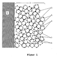
- FIG. 1 shows the structure of the inhomogeneous microstructure of FIG reaction layers according to the invention.
- (1) denotes the Polymer electrolyte membrane. On this membrane is the reaction layer (2) applied.
- (3) and (6) denote the Carbon carrier particles and (4) on the carrier particles deposited crystallites of the catalytically active metal components.
- the carbon particles (3) belong to the Catalyst content A1. They are soaked with ionomer and imbedded in the ionomer, which is surrounded by the particles (3) Ionomer shell (5) is illustrated.
- the carbon particles (6) belong to the catalyst portion A2. you are neither impregnated with ionomer nor embedded in the ionomer. Between the particles are pores (7), which through the evaporating solvent B was left behind.
- Examples 1-4 describe the preparation of membrane electrode assemblies according to the invention, while comparative example VB1 shows the preparation of a membrane electrode assembly according to US Pat. No. 5,234,777, Protocol II. All membrane electrode assemblies were tested in a PEM fuel cell with an area of the electrode of 25 cm 2 in pressureless hydrogen / air operation (1bar / 1bar). The material used for gas distribution was TGP-H-090/30% wet proof carbon fiber paper from ETEK Inc., Natick (USA).
- Polymer electrolyte membranes can exist in an acidic, proton-conducting H + form or after exchange of the protons for monovalent ions such as Na + and K + in a nonazide Na + or K + form.
- the nonazidic form of the polymer membranes is usually more resistant to thermal stresses than their acidic form.
- the proton conducting materials were used in their Na + form.
- the ionomers were converted back into the acidic, proton-conducting form by so-called re-protonation.
- the back protonation was carried out by treating the membrane-electrode units in sulfuric acid.
- a MEA was prepared as follows: A dispersion of 1 g of Pt / C catalyst (supported catalyst 20% Pt on Vulcan XC72), 10 g of a 5% Nafion solution in low-boiling alcohols (Aldrich, Düsseldorf), 3.3 g of glycerol, 8.2 g of water and 0.47 g of 1N NaOH solution. The mixture was dispersed in an ultrasonic bath. A Nafion® 115 membrane in Na + form was attached to a heated plate. The mixture was applied to one side of the membrane and dried at 150 ° C. This procedure was repeated until the desired platinum loading of 0.25 mg Pt / cm 2 was reached.
- the back of the membrane was coated in the same way.
- the catalyst-coated membrane was reprotonated in 0.5 M sulfuric acid solution.
- the layer thickness of the electrode was 10 ⁇ m.
- the total loading of the membrane-electrode assembly with platinum was 0.5 mg / cm 2 .
- the inks A and B of Examples 1 to 4 were each combined into an ink C and thoroughly homogenized.
- the final inks had the properties shown in Table 1: Properties of the finished inks C example 1 2 3 4 viscosity 1.3 1.5 0.43 1.8 Pa.s Proportion of solvent B to total amount of solvents A + B 22.2 18.8 7.9 10.0 Wt .-% Part A2 of the catalyst dispersed in Ink B, based on A1 + A2 20 10.5 19.7 18.8 Wt .-% A1: A2 4: 1 9: 1 4: 1 4.4: 1
- the viscosity of the inks was measured with a Haake RV20 rotational viscosimeter at 100 s -1 .
- the inks were screen printed on Nafion® 115 membranes in the Na + form and dried at 110 ° C. Subsequently, the back side of the membranes was coated with the catalyst ink in the same manner. Reprotonation was carried out in 0.5 M sulfuric acid.
- the platinum loading per reaction layer was 0.225 mg Pt / cm 2 in all examples according to the invention. This corresponded to a total loading of the membrane electrode assembly with platinum of 0.45 mg / cm 2 .
- the layer thicknesses were in the range between 20 and 25 microns.
- the reaction layers of the invention showed a significantly larger pore volume compared to the reaction layers of Comparative Example 1.
- the improved pore volume was achieved without the addition of external pore-forming agents.
- the pore volumes measured for Example 3 and Comparative Example 1 are listed in Table 2.
- the reaction layers according to the invention are characterized by a larger pore volume and by a different pore structure.
- the pore radii in the region of the maximum of the pore distribution in the reaction layers according to the invention are about twice as large as in Comparative Example 1.
- FIGS. 4 and 5 show the measurement curves of the porosimeter measurements for the differential penetration of the mercury into the pores of the layers.
- the inhomogeneous microstructure of this invention reaction layers described was with XPS (X-ray photoelutron spectroscopy). This measuring method provides information about the chemical composition and the oxidation state in the uppermost atomic layers of the examined surface.
- Table 3 shows the binding energies of sulfur XPS bands for the platinum supported catalyst and for the reaction layers of Example 1 and Comparative Example 1.
- XPS data Catalyst 20% Pt on Vulcan XC72 example 1 Comparative Example 1
- the sulfur band at 163.6 eV of the catalyst can be assigned to the Sulfan phenomenon on the surface of the used as a carrier Vulcan XC72.
- the band at 168.4 eV found in the investigation of the membrane-electrode assembly of the comparative example is caused by the SO 3 H groups of Nafion. In this case, the band of the Sulfan phenomenon is not found, which shows that the catalyst particles of this reaction layer are completely covered with Nafion.
- Example 1 exhibits both XPS bands-the sulfane band of the catalyst support and the SO 3 H band of the Nafion. This clearly shows that a significant proportion of the catalyst particles are not embedded in Nafion, as shown in Figure 1 for the catalyst particles 6.
- the measured cell voltages in hydrogen / air operation in Dependence on the current density are exemplary in FIG 2 for the cells of Comparative Example 1 and Example 1 and in Figure 2 for the cells of Comparative Example 1 and of Example 2 shown. It can be seen that the Membrane electrode units according to the invention a significantly improved electrical performance compared to State of the art (VB1) deliver.
- Table 3 shows the cell voltages still measured when the cells are loaded at a current density of 500 mA / cm 2 .
- Cell voltages in hydrogen / air operation at 500 mA / cm 2 example Cell voltage [mV] Comparative Example 1 436 example 1 540 Example 2 530 Example 3 495 Example 4 487
Landscapes
- Chemical & Material Sciences (AREA)
- Chemical Kinetics & Catalysis (AREA)
- General Chemical & Material Sciences (AREA)
- Engineering & Computer Science (AREA)
- Electrochemistry (AREA)
- Manufacturing & Machinery (AREA)
- Materials Engineering (AREA)
- Physics & Mathematics (AREA)
- Thermal Sciences (AREA)
- Life Sciences & Earth Sciences (AREA)
- Sustainable Development (AREA)
- Sustainable Energy (AREA)
- Inert Electrodes (AREA)
- Fuel Cell (AREA)
Abstract
Description
- Figur 1:
- Aufbau der erfindungsgemäßen Reaktionsschichten
- Figur 2:
- Zellspannung in Abhängigkeit von der Stromdichte bei Luftbetrieb für die MEE von Beispiel 1 und Vergleichsbeispiel 1
- Figur 3:
- Zellspannung in Abhängigkeit von der Stromdichte bei Luftbetrieb für die MEE von Beispiel 2 und Vergleichsbeispiel 1
- Figur 4:
- Porosimeterkurve für Vergleichsbeispiel 1
- Figur 5:
- Porosimeterkurve für Beispiel 3
| Zur Herstellung einer Membran-Elektroden-Einheit wurden die folgenden Tinten hergestellt : | ||
| Tinte A | Trägerkatalysator 20% Pt auf Vulcan XC 72 | 24 g |
| Nafion-Lösung (6,7% in Propylenglykol) | 150,0 g | |
| Natronlauge (10%) | 3,0 g | |
| Tinte B | Trägerkatalysator 20% Pt auf Vulcan XC 72 | 6 g |
| Dodecansäuremethylester | 40 g | |
| Natronlauge (10%) | 1 g |
| Zur Herstellung einer weiteren Membran-Elektroden-Einheit wurden folgende Tinten hergestellt: | ||
| Tinte A | Trägerkatalysator 20% Pt auf Vulcan XC 72 | 11,1 g |
| Nafion-Lösung (5,4% in Propylenglykol) | 74,0 g | |
| Natronlauge (10%) | 1,0 g | |
| Tinte B | Trägerkatalysator 20% Pt auf Vulcan XC 72 | 1,3 g |
| Dodecansäuremethylester | 16,3 g | |
| Natronlauge (10%) | 0,7 g |
| Es wurden die folgenden Tinten hergestellt: | ||
| Tinte A | Trägerkatalysator 20% Pt auf Vulcan XC 72 | 16,7 g |
| Nafion-Lösung (4,15% in Propylenglykol) | 164,0 g | |
| Natronlauge (10%) | 2,0 g | |
| Tinte B | Trägerkatalysator 20% Pt auf Vulcan XC 72 | 4,1 g |
| Dodecansäuremethylester | 13,5 g | |
| Natronlauge (10%) | 0,5 g |
| Zur Herstellung einer weiteren Membran-Elektroden-Einheit wurden folgende Tinten hergestellt: | ||
| Tinte A | Trägerkatalysator 20% Pt auf Vulcan XC 72 | 10,8 g |
| Nafion-Lösung (3,8% in Propylenglykol) | 117,0 g | |
| Natronlauge (10%) | 1,5 g | |
| Tinte B | Trägerkatalysator 20% Pt auf Vulcan XC 72 | 2,5 g |
| Shellsol D70 (Fa. Shell) | 12,5 g | |
| Natronlauge (10%) | 0,5 g |
| Eigenschaften der fertigen Tinten C | |||||
| Beispiel | |||||
| 1 | 2 | 3 | 4 | ||
| Viskosität | 1,3 | 1,5 | 0,43 | 1,8 | Pa·s |
| Anteil des Lösungsmittels B an Gesamtmenge der Lösungsmittel A+B | 22,2 | 18,8 | 7,9 | 10,0 | Gew.-% |
| Anteil A2 des in Tinte B dispergierten Katalysators, bezogen auf A1+A2 | 20 | 10,5 | 19,7 | 18,8 | Gew.-% |
| A1:A2 | 4:1 | 9:1 | 4:1 | 4,4:1 |
| Porenvolumen und Porenverteilung | ||
| Beispiel | Porenvolumen d=0,03 bis 1 µm [ml/g] | Maximum der Porenverteilung bei [µm] |
| VB1 | 0,6 | 0,09 |
| B3 | 0,88 | 0,2 |
| XPS-Daten | Katalysator 20% Pt auf Vulcan XC72 | Beispiel 1 | Vergleichs-beispiel 1 |
| Bindungsenergie (eV) | 163,7 | 168,7/163,6 | 168,4 |
| Zellspannungen im Wasserstoff/Luftbetrieb bei 500 mA/cm2 | |
| Beispiel | Zellspannung [mV] |
| Vergleichsbeispiel 1 | 436 |
| Beispiel 1 | 540 |
| Beispiel 2 | 530 |
| Beispiel 3 | 495 |
| Beispiel 4 | 487 |
Claims (15)
- Tinte zur Herstellung von Membran-Elektroden-Einheiten für Polymer-Elektrolyt-Brennstoffzellen, welche einen Katalysator, ein Ionomer und organische Lösungsmittel aufweist,
dadurch gekennzeichnet, daß als organische Lösungsmittel ein- und mehrwertige Alkohole, Glykole sowie Glykoletheralkohole und
Glykolether mit einer Verdunstungszahl größer 600, bevorzugt größer 800, zum Einsatz kommen. - Tinte nach Anspruch 1,
dadurch gekennzeichnet, daß als organische Lösungsmittel Propylenglykol, Dipropylenglykol, Glycerin oder Hexylenglykol oder Mischungen davon verwendet werden. - Tinte nach Anspruch 1,
dadurch gekennzeichnet, daß als organisches Lösungsmittel Propylenglykol verwendet wird. - Tinte nach Anspruch 1,
dadurch gekennzeichnet, daß es sich bei dem Ionomer um ein Tetrafluorethylen-Fluorvinylether-Copolymer mit Säuregruppen handelt. - Tinte nach Anspruch 1,
dadurch gekennzeichnet, daß das Ionomer in einer azidischen, Protonen leitenden H+-Form oder in einer nichtazidischen Form, vorzugsweise in einer nichtazidischen Na+- oder K+-Form, vorliegt. - Tinte nach Anspruch 1,
dadurch gekennzeichnet, daß das Ionomer in einer Konzentration von 1 bis 10 Gew.-%, bezogen auf das Gesamtgewicht der Lösung, in den organischen Lösungsmitteln gelöst ist. - Tinte nach Anspruch 1,
dadurch gekennzeichnet, daß es sich bei dem Katalysator um Trägerkatalysatoren von katalytisch aktiven Platingruppenmetallen oder Legierungen davon auf einem elektrisch leitfähigen und hochoberflächigen Kohlenstoff handelt. - Tinte nach Anspruch 1,
dadurch gekennzeichnet, daß es sich bei dem Katalysator um Mohre der Platingruppenmetalle oder Legierungen davon handelt. - Tinte nach Anspruch 1,
dadurch gekennzeichnet, daß sie weiterhin Wasser enthält. - Tinte nach Anspruch 1,
dadurch gekennzeichnet, daß sie weiterhin Natronlauge enthält. - Verfahren zur Herstellung einer Membran-Elektroden-Einheit für Polymer-Elektrolyt-Brennstoffzellen
dadurch gekennzeichnet, daß eine Polymer-Elektrolyt-Membran mit einer Tinte beschichtet wird, die einen Katalysator, ein Ionomer und organische Lösungsmittel aufweist, wobei als organische Lösungsmittel ein- und mehrwertige Alkohole, Glykole sowie Glykoletheralkohole und Glykolether mit einer Verdunstungszahl größer 600, bevorzugt größer 800, zum Einsatz kommen. - Verfahren gemäß Anspruch 11, wobei die Beschichtung im Siebdruckverfahren erfolgt.
- Verfahren nach Anspruch 11, wobei die Beschichtung bei Temperaturen zwischen 60 und 140°C, bevorzugt zwischen 70 und 120°C, getrocknet wird.
- Verwendung der Tinte gemäß einem der Ansprüche 1 bis 10 zur Herstellung von Membran-Elektroden-Einheiten für Polymer-Elektrolyt-Brennstoffzellen.
- Verwendung der Tinte gemäß einem der Ansprüche 1 bis 10 in einem Verfahren zur Herstellung von Membran-Elektroden-Einheiten für Polymer-Elektrolyt-Brennstoffzellen.
Applications Claiming Priority (3)
| Application Number | Priority Date | Filing Date | Title |
|---|---|---|---|
| DE19812592A DE19812592B4 (de) | 1998-03-23 | 1998-03-23 | Membran-Elektroden-Einheit für Polymer-Elektrolyt-Brennstoffzellen, Verfahren zu ihrer Herstellung sowie Tinte |
| DE19812592 | 1998-03-23 | ||
| EP99104630A EP0945910B1 (de) | 1998-03-23 | 1999-03-09 | Membran-Elektroden-Einheit für Polymer-Elektrolyt-Brennstoffzellen und Verfahren zu ihrer Herstellung |
Related Parent Applications (1)
| Application Number | Title | Priority Date | Filing Date |
|---|---|---|---|
| EP99104630A Division EP0945910B1 (de) | 1998-03-23 | 1999-03-09 | Membran-Elektroden-Einheit für Polymer-Elektrolyt-Brennstoffzellen und Verfahren zu ihrer Herstellung |
Publications (1)
| Publication Number | Publication Date |
|---|---|
| EP1536504A1 true EP1536504A1 (de) | 2005-06-01 |
Family
ID=7861907
Family Applications (2)
| Application Number | Title | Priority Date | Filing Date |
|---|---|---|---|
| EP05003955A Ceased EP1536504A1 (de) | 1998-03-23 | 1999-03-09 | Tinte zur Herstellung von Membran-Elektroden-Einheiten sowie Verfahren zu ihrer Verwendung |
| EP99104630A Expired - Lifetime EP0945910B1 (de) | 1998-03-23 | 1999-03-09 | Membran-Elektroden-Einheit für Polymer-Elektrolyt-Brennstoffzellen und Verfahren zu ihrer Herstellung |
Family Applications After (1)
| Application Number | Title | Priority Date | Filing Date |
|---|---|---|---|
| EP99104630A Expired - Lifetime EP0945910B1 (de) | 1998-03-23 | 1999-03-09 | Membran-Elektroden-Einheit für Polymer-Elektrolyt-Brennstoffzellen und Verfahren zu ihrer Herstellung |
Country Status (8)
| Country | Link |
|---|---|
| US (1) | US6309772B1 (de) |
| EP (2) | EP1536504A1 (de) |
| JP (1) | JP4465058B2 (de) |
| KR (1) | KR100638498B1 (de) |
| BR (1) | BR9900605A (de) |
| CA (1) | CA2266239C (de) |
| DE (1) | DE19812592B4 (de) |
| DK (1) | DK0945910T3 (de) |
Cited By (1)
| Publication number | Priority date | Publication date | Assignee | Title |
|---|---|---|---|---|
| WO2007054570A1 (de) * | 2005-11-14 | 2007-05-18 | Basf Se | Aminhaltige katalysatortinte für brennstoffzellen |
Families Citing this family (69)
| Publication number | Priority date | Publication date | Assignee | Title |
|---|---|---|---|---|
| JP4433518B2 (ja) * | 1999-07-30 | 2010-03-17 | アイシン精機株式会社 | 固体高分子電解質型燃料電池 |
| JP4093439B2 (ja) * | 1999-08-27 | 2008-06-04 | 松下電器産業株式会社 | 高分子電解質型燃料電池用電極の製造法 |
| US6528201B1 (en) * | 1999-09-27 | 2003-03-04 | Japan Storage Battery Co., Ltd. | Electrode for fuel cell and process for producing the same |
| DE19951936A1 (de) | 1999-10-28 | 2001-05-10 | Forschungszentrum Juelich Gmbh | Herstellung von Katalysatorschichten auf Membranen für Niedertemperatur-Brennstoffzellen |
| US6602630B1 (en) * | 2000-03-14 | 2003-08-05 | The Electrosynthesis Company, Inc. | Membrane electrode assemblies for electrochemical cells |
| NL1014696C2 (nl) | 2000-03-20 | 2001-09-28 | Stichting Energie | Vervaardiging van lage-temperatuur brandstofcel elektroden. |
| JP3614077B2 (ja) * | 2000-03-22 | 2005-01-26 | トヨタ自動車株式会社 | 燃料電池用の電極触媒溶液およびその製造方法 |
| EP1150369B1 (de) | 2000-04-28 | 2003-07-02 | OMG AG & Co. KG | Gasverteilerstrukturen und Gasdiffusionselektroden für Polymerelektrolyt-Brennstoffzellen |
| WO2001094450A2 (en) | 2000-06-02 | 2001-12-13 | Sri International | Polymer membrane composition |
| WO2001099216A1 (en) * | 2000-06-22 | 2001-12-27 | Matsushita Electric Industrial Co., Ltd. | Polymer electrolyte fuel cell, method for manufacturing electrode thereof, and manufacturing apparatus |
| KR100468102B1 (ko) | 2000-07-03 | 2005-01-26 | 마쯔시다덴기산교 가부시키가이샤 | 고분자 전해질형 연료전지 |
| DE10037074A1 (de) | 2000-07-29 | 2002-02-14 | Omg Ag & Co Kg | Tinte zur Herstellung von Membran-Elektroden-Einheiten für PEM-Brennstoffzellen |
| DE10037072A1 (de) * | 2000-07-29 | 2002-02-14 | Omg Ag & Co Kg | Membran-Elektrodeneinheit für Polymerelektrolyt-Brennstoffzellen und Verfahren zu ihrer Herstellung |
| WO2002013297A1 (en) * | 2000-08-04 | 2002-02-14 | Matsushita Electric Industrial Co., Ltd. | Polyelectrolyte fuel cell and production method therefor |
| DE10141647B4 (de) * | 2000-09-11 | 2008-01-17 | H.I.A.T. Ggmbh | Verfahren zur Herstellung einer Membran-Elektroden-Einheit und deren Verwendung |
| US20040185325A1 (en) * | 2000-10-27 | 2004-09-23 | Faguy Peter M | Fuel cell having improved catalytic layer |
| JP2002216778A (ja) * | 2001-01-15 | 2002-08-02 | Aisin Seiki Co Ltd | 燃料電池用電極およびその製造方法および固体高分子電解質型燃料電池 |
| US6663998B2 (en) | 2001-04-05 | 2003-12-16 | The Technical University Of Denmark (Dtu) | Anode catalyst materials for use in fuel cells |
| ATE400904T1 (de) | 2001-06-01 | 2008-07-15 | Polyfuel Inc | Austauschbare brennstoffpatrone, brennstoffzellenaggregat mit besagter brennstoffpatrone für tragbare elektronische geräte und entsprechendes gerät |
| US7316855B2 (en) | 2001-06-01 | 2008-01-08 | Polyfuel, Inc. | Fuel cell assembly for portable electronic device and interface, control, and regulator circuit for fuel cell powered electronic device |
| DE10226073B8 (de) * | 2001-06-13 | 2007-10-18 | Honda Giken Kogyo K.K. | Elektrode für eine ein Festpolymerelektrolyt aufweisende Brennstoffzelle und Herstellungsverfahren dafür |
| CA2407202C (en) * | 2001-10-11 | 2009-11-03 | Honda Giken Kogyo Kabushiki Kaisha | Electrode for polymer electrolyte fuel cell |
| US6805983B1 (en) | 2002-02-11 | 2004-10-19 | H Power Corporation | Activation of electrochemical cells with catalyst electrodes |
| AU2003223846A1 (en) * | 2002-02-28 | 2003-09-29 | Thomas Haring | Layered structures and method for producing the same |
| DK1341250T3 (da) * | 2002-02-28 | 2011-08-22 | Umicore Ag & Co Kg | Fremgangsmåde til fremstilling af katalysatorbelagte membraner og membram-elektroenheder til brændstofceller |
| US6869704B1 (en) | 2002-03-05 | 2005-03-22 | H Power Corporation | Enhancement of electrochemical cell performance |
| US6833212B2 (en) * | 2002-03-29 | 2004-12-21 | Hewlett-Packard Development Company, L.P. | Electrolyte for a fuel cell |
| US20030190517A1 (en) * | 2002-04-08 | 2003-10-09 | John Elter | Fuel cell |
| US7354679B2 (en) | 2002-05-13 | 2008-04-08 | Polyfuel, Inc. | Ion conductive random copolymers |
| EP1518290A4 (de) | 2002-05-13 | 2009-12-02 | Polyfuel Inc | Ionenleitende blockcopolymere |
| WO2003095509A1 (en) | 2002-05-13 | 2003-11-20 | Polyfuel, Inc. | Sulfonated copolymer |
| US7220693B1 (en) | 2002-06-27 | 2007-05-22 | H Power Corporation | Fuel cell catalyst electrodes |
| US7108773B2 (en) * | 2002-09-11 | 2006-09-19 | The Board Of Trustees Of The University Of Illinois | Solids supporting mass transfer for fuel cells and other applications and solutions and methods for forming |
| DE60226732D1 (de) * | 2002-09-30 | 2008-07-03 | Umicore Ag & Co Kg | Mit Katalysator beschichtete Ionomer-Membran mit Schutzfilm und daraus hergestellte Membran-Elektroden-Anordnung |
| JP2004241362A (ja) * | 2002-12-09 | 2004-08-26 | Toyota Motor Corp | 膜電極接合体およびその製造方法 |
| US20050014056A1 (en) * | 2003-07-14 | 2005-01-20 | Umicore Ag & Co. Kg | Membrane electrode unit for electrochemical equipment |
| US8394551B2 (en) * | 2003-07-14 | 2013-03-12 | Umicore Ag & Co. Kg | Membrane electrode assembly for use in electrochemical devices |
| US20050112450A1 (en) * | 2003-09-08 | 2005-05-26 | Intematix Corporation | Low platinum fuel cell catalysts and method for preparing the same |
| US8211593B2 (en) * | 2003-09-08 | 2012-07-03 | Intematix Corporation | Low platinum fuel cells, catalysts, and method for preparing the same |
| JP4290524B2 (ja) * | 2003-10-23 | 2009-07-08 | 株式会社キャタラー | 燃料電池用カソード触媒 |
| CN1874841B (zh) * | 2003-10-29 | 2010-09-15 | 尤米科尔股份公司及两合公司 | 水电解用贵金属氧化物催化剂 |
| WO2005053073A1 (ja) * | 2003-11-26 | 2005-06-09 | Hitachi Maxell, Ltd. | 液体燃料電池用発電素子およびその製造方法、並びにそれを用いた液体燃料電池 |
| US7396611B2 (en) * | 2003-12-15 | 2008-07-08 | Plug Power Inc. | Fuel cell catalyst layer |
| US7108930B2 (en) * | 2003-12-17 | 2006-09-19 | Plug Power, Inc. | Fuel cells |
| US20050136298A1 (en) * | 2003-12-19 | 2005-06-23 | Manikandan Ramani | Methods of treating fuel cells and fuel cell systems |
| JP4228911B2 (ja) * | 2003-12-25 | 2009-02-25 | パナソニック株式会社 | 燃料電池とその製造方法 |
| DE102004028141C5 (de) * | 2004-06-10 | 2015-11-19 | Elcomax Membranes Gmbh | Membran-Elektroden-Modul (MEA) für eine Brennstoffzelle und Brennstoffzellenstapel |
| US20080020253A1 (en) * | 2004-07-09 | 2008-01-24 | Ingo Neubert | Method for Producing a Membrane-Electrode Unit |
| US8110248B2 (en) * | 2005-02-14 | 2012-02-07 | Masaru Hori | Fuel cell structure and method of manufacturing same |
| AU2006214086B2 (en) * | 2005-02-17 | 2012-01-19 | Monsanto Technology Llc | Transition metal-containing catalysts and catalyst combinations including transition metal-containing catalysts and processes for their preparation and use as oxidation catalysts |
| US20060199059A1 (en) * | 2005-03-01 | 2006-09-07 | Xu Helen X | Ion conductive polymer electrolyte and its membrane electrode assembly |
| EP2273591B1 (de) | 2005-03-30 | 2017-05-31 | Umicore Ag & Co. Kg | Tinte zur Herstellung von Katalysatorschichten |
| JP2007141477A (ja) * | 2005-11-15 | 2007-06-07 | Hitachi Ltd | 触媒材料及びそれを用いた電解質膜−電極接合体と燃料電池 |
| US7368200B2 (en) * | 2005-12-30 | 2008-05-06 | Tekion, Inc. | Composite polymer electrolyte membranes and electrode assemblies for reducing fuel crossover in direct liquid feed fuel cells |
| WO2007098432A2 (en) * | 2006-02-17 | 2007-08-30 | Monsanto Technology Llc | Transition metal-containing catalysts and processes for their preparation and use as fuel cell catalysts |
| US8603703B2 (en) * | 2006-07-26 | 2013-12-10 | GM Global Technology Operations LLC | Method for making super-hydrophilic and electrically conducting surfaces for fuel cell bipolar plates |
| EP2053673A4 (de) | 2006-08-07 | 2011-07-06 | Mitsubishi Gas Chemical Co | Elektrode für eine brennstoffzelle, herstellungsverfahren dafür und brennstoffzelle |
| US20080044720A1 (en) * | 2006-08-18 | 2008-02-21 | Elchem Tech Co., Ltd. | Membrane electrode assembly having porous electrode layers, manufacturing method thereof, and electrochemical cell comprising the same |
| KR100969476B1 (ko) * | 2006-12-12 | 2010-07-14 | 주식회사 엘지화학 | 연료전지용 막-전극 접합체 및 연료전지 |
| DE102007028007A1 (de) * | 2007-06-14 | 2008-12-24 | BLüCHER GMBH | Brennstoffzelle mit Katalysator und deren Verwendung |
| US7981319B2 (en) * | 2009-03-19 | 2011-07-19 | Los Alamos National Security, Llc | Non-aqueous liquid compositions comprising ion exchange polymers |
| FR2958797B1 (fr) * | 2010-04-13 | 2012-04-27 | Commissariat Energie Atomique | Structuration d'electrode de piles a combustible a membrane echangeuse de protons |
| EP2608297A1 (de) | 2011-12-22 | 2013-06-26 | Umicore AG & Co. KG | Edelmetall-Oxidkatalysator für die Wasserlektrolyse |
| JP5807654B2 (ja) * | 2013-03-28 | 2015-11-10 | トヨタ自動車株式会社 | 燃料電池用の触媒インクの製造方法、燃料電池用の触媒層の製造方法、燃料電池用の膜電極接合体の製造方法 |
| GB201322494D0 (en) | 2013-12-19 | 2014-02-05 | Johnson Matthey Fuel Cells Ltd | Catalyst layer |
| US10446851B2 (en) * | 2016-10-17 | 2019-10-15 | Ford Global Technologies, Llc | Nanostructured PEMFC electrode |
| EP3780192B1 (de) * | 2018-03-30 | 2024-06-05 | Toppan Printing Co., Ltd. | Membranelektrodenanordnung und feststoffpolymer-elektrolyt-brennstoffzelle |
| KR102777688B1 (ko) * | 2018-12-06 | 2025-03-06 | 현대자동차주식회사 | 산소반응성이 향상된 연료전지용 전극 및 이의 제조방법 |
| EP4395930A4 (de) * | 2021-09-03 | 2026-04-22 | Blue O Tech Inc | Elektrochemische hdv-fertigelektroden mit neuartiger zusammensetzung, struktur und verfahren zur herstellung |
Citations (7)
| Publication number | Priority date | Publication date | Assignee | Title |
|---|---|---|---|---|
| WO1992015121A1 (en) * | 1991-02-19 | 1992-09-03 | United States Department Of Energy | Membrane catalyst layer for fuel cells |
| US5211984A (en) * | 1991-02-19 | 1993-05-18 | The Regents Of The University Of California | Membrane catalyst layer for fuel cells |
| EP0622861A1 (de) * | 1993-04-26 | 1994-11-02 | E.I. Du Pont De Nemours & Company Incorporated | Membran-Elektrode Struktur |
| WO1994025993A1 (en) * | 1993-04-26 | 1994-11-10 | E.I. Du Pont De Nemours And Company | Method of imprinting catalytically active particles on membrane |
| DE19602629A1 (de) * | 1995-01-26 | 1996-08-01 | Matsushita Electric Industrial Co Ltd | Verfahren zum Herstellen einer Feststoffpolymerelektrolyt-Brennstoffzelle |
| EP0788173A1 (de) * | 1996-02-05 | 1997-08-06 | Honda Giken Kogyo Kabushiki Kaisha | Verfahren zur Herstellung einer Elektrodeneinheit für eine Brennstoffzelle |
| EP1176652A2 (de) * | 2000-07-29 | 2002-01-30 | OMG AG & Co. KG | Tinte zur Herstellung von Membran-Elektroden-Einheiten für PEM-Brennstoffzellen |
Family Cites Families (9)
| Publication number | Priority date | Publication date | Assignee | Title |
|---|---|---|---|---|
| US4876115A (en) | 1987-01-30 | 1989-10-24 | United States Department Of Energy | Electrode assembly for use in a solid polymer electrolyte fuel cell |
| GB9213124D0 (en) * | 1992-06-20 | 1992-08-05 | Johnson Matthey Plc | High performance electrode |
| US6054230A (en) * | 1994-12-07 | 2000-04-25 | Japan Gore-Tex, Inc. | Ion exchange and electrode assembly for an electrochemical cell |
| US5620807A (en) * | 1995-08-31 | 1997-04-15 | The Dow Chemical Company | Flow field assembly for electrochemical fuel cells |
| EP0853824B1 (de) * | 1995-10-06 | 2003-07-23 | Dow Global Technologies Inc. | Fluessigkeitsverteilungsstrukturen fuer membran-elektrode-anordnungen von brennstoffzellen |
| US5869201A (en) * | 1995-12-22 | 1999-02-09 | George Marchetti | Hydrophilic, graphite fuel cell electrode for use with an ionomer membrane |
| JPH09199138A (ja) * | 1996-01-19 | 1997-07-31 | Toyota Motor Corp | 燃料電池用の電極または電極・電解質膜接合体の製造方法および燃料電池用の電極 |
| DE19606612A1 (de) * | 1996-02-22 | 1997-08-28 | Forschungszentrum Juelich Gmbh | Elektrolyt-Gasdiffusionselektroden-Einheit |
| DE19611510A1 (de) * | 1996-03-23 | 1997-09-25 | Degussa | Gasdiffusionselektrode für Membranbrennstoffzellen und Verfahren zu ihrer Herstellung |
-
1998
- 1998-03-23 DE DE19812592A patent/DE19812592B4/de not_active Expired - Fee Related
-
1999
- 1999-03-09 EP EP05003955A patent/EP1536504A1/de not_active Ceased
- 1999-03-09 DK DK99104630.1T patent/DK0945910T3/da active
- 1999-03-09 EP EP99104630A patent/EP0945910B1/de not_active Expired - Lifetime
- 1999-03-22 KR KR1019990009608A patent/KR100638498B1/ko not_active Expired - Fee Related
- 1999-03-22 CA CA2266239A patent/CA2266239C/en not_active Expired - Fee Related
- 1999-03-22 US US09/274,018 patent/US6309772B1/en not_active Expired - Lifetime
- 1999-03-23 JP JP07786199A patent/JP4465058B2/ja not_active Expired - Fee Related
- 1999-03-23 BR BR9900605-7A patent/BR9900605A/pt not_active Application Discontinuation
Patent Citations (7)
| Publication number | Priority date | Publication date | Assignee | Title |
|---|---|---|---|---|
| WO1992015121A1 (en) * | 1991-02-19 | 1992-09-03 | United States Department Of Energy | Membrane catalyst layer for fuel cells |
| US5211984A (en) * | 1991-02-19 | 1993-05-18 | The Regents Of The University Of California | Membrane catalyst layer for fuel cells |
| EP0622861A1 (de) * | 1993-04-26 | 1994-11-02 | E.I. Du Pont De Nemours & Company Incorporated | Membran-Elektrode Struktur |
| WO1994025993A1 (en) * | 1993-04-26 | 1994-11-10 | E.I. Du Pont De Nemours And Company | Method of imprinting catalytically active particles on membrane |
| DE19602629A1 (de) * | 1995-01-26 | 1996-08-01 | Matsushita Electric Industrial Co Ltd | Verfahren zum Herstellen einer Feststoffpolymerelektrolyt-Brennstoffzelle |
| EP0788173A1 (de) * | 1996-02-05 | 1997-08-06 | Honda Giken Kogyo Kabushiki Kaisha | Verfahren zur Herstellung einer Elektrodeneinheit für eine Brennstoffzelle |
| EP1176652A2 (de) * | 2000-07-29 | 2002-01-30 | OMG AG & Co. KG | Tinte zur Herstellung von Membran-Elektroden-Einheiten für PEM-Brennstoffzellen |
Non-Patent Citations (1)
| Title |
|---|
| MAKOTO UCHIDA ET AL: "NEW PREPARATION METHOD FOR POLYMER-ELECTROLYTE FUEL CELLS", JOURNAL OF THE ELECTROCHEMICAL SOCIETY, ELECTROCHEMICAL SOCIETY. MANCHESTER, NEW HAMPSHIRE, US, vol. 142, no. 2, February 1995 (1995-02-01), pages 463 - 468, XP002155036, ISSN: 0013-4651 * |
Cited By (1)
| Publication number | Priority date | Publication date | Assignee | Title |
|---|---|---|---|---|
| WO2007054570A1 (de) * | 2005-11-14 | 2007-05-18 | Basf Se | Aminhaltige katalysatortinte für brennstoffzellen |
Also Published As
| Publication number | Publication date |
|---|---|
| BR9900605A (pt) | 2000-06-06 |
| EP0945910A3 (de) | 2004-01-07 |
| JPH11329452A (ja) | 1999-11-30 |
| CA2266239C (en) | 2011-04-19 |
| KR19990078111A (ko) | 1999-10-25 |
| JP4465058B2 (ja) | 2010-05-19 |
| EP0945910A2 (de) | 1999-09-29 |
| US6309772B1 (en) | 2001-10-30 |
| KR100638498B1 (ko) | 2006-10-26 |
| CA2266239A1 (en) | 1999-09-23 |
| DE19812592B4 (de) | 2004-05-13 |
| DK0945910T3 (da) | 2012-08-20 |
| DE19812592A1 (de) | 1999-10-07 |
| EP0945910B1 (de) | 2012-05-30 |
Similar Documents
| Publication | Publication Date | Title |
|---|---|---|
| EP0945910B1 (de) | Membran-Elektroden-Einheit für Polymer-Elektrolyt-Brennstoffzellen und Verfahren zu ihrer Herstellung | |
| EP1176653B1 (de) | Membran-Elektrodeneinheit für Polymerelektrolyt-Brennstoffzellen und Verfahren zu ihrer Herstellung | |
| EP0987777B1 (de) | Katalysatorschicht für Polymer-Elektrolyt-Brennstoffzellen | |
| EP0797265B1 (de) | Gasdiffusionselektrode für Membranbrennstoffzellen und Verfahren zu ihrer Herstellung | |
| DE112007000670B4 (de) | Brennstoffzelle und Herstellungsverfahren für eine Brennstoffzelle | |
| EP1150369B1 (de) | Gasverteilerstrukturen und Gasdiffusionselektroden für Polymerelektrolyt-Brennstoffzellen | |
| EP1176652B1 (de) | Tinte zur Herstellung von Membran-Elektroden-Einheiten für PEM-Brennstoffzellen | |
| DE102009004529B4 (de) | Membranelektrodenanordnung mit niedriger Ionomerkonzentration an der Oberfläche und Herstellungsverfahren | |
| DE102019105413A1 (de) | Verbundelektrodenschicht für eine polymerelektrolyt- brennstoffzelle | |
| DE102010028242A1 (de) | Elektrode für eine Polymer-Elektrolyt-Membran-Brennstoffzelle und Verfahren zum Bilden einer Membran-Elektroden-Anordnung unter Verwendung derselben | |
| DE102017123939A1 (de) | Nanostrukturierte PEMFC-Elektrode | |
| WO1997020358A1 (de) | Gasdiffusionselektrode für polymerelektrolytmembran-brennstoffzellen | |
| DE10159476A1 (de) | Verfahren zur Herstellung von Membran-Elektrodeneinheiten für Brennstoffzellen | |
| EP3596767B1 (de) | Katalytische zusammensetzung, verfahren zu ihrer herstellung, ihre verwendung zur herstellung einer brennstoffzellenelektrode sowie brennstoffzelle mit einer solchen | |
| DE112015002354T5 (de) | Membran-elektroden-anordnung | |
| DE102018102588A1 (de) | Katalysatortinte für Brennstoffzelle, Katalysatorschicht für Brennstoffzelle, und Membranelektrodeneinheit | |
| DE102022106413A1 (de) | Katalysatorschicht und verfahren zur herstellung derselben | |
| DE112006001729B4 (de) | Spannungswechselbeständige Brennstoffzelleneletrokatalysatorschicht, Brennstoffzelle umfassend dieselbe und Verwendung derselben | |
| DE102017215428A1 (de) | Katalytische Zusammensetzung, Verfahren zu ihrer Herstellung, ihre Verwendung zur Herstellung einer Brennstoffzellenelektrode sowie Brennstoffzelle mit einer solchen | |
| DE60101797T2 (de) | Herstellungsverfahren von niedertemperatur- brennstoffzellenelektroden | |
| DE10250884A1 (de) | Elektrode für Polymerelektrolytbrennstoffzellen und Verfahren zur Herstellung derselben | |
| EP1150370A2 (de) | Gasverteilerstrukturen und Gasdiffusionselektroden für Polymerelektrolyt-Brennstoffzellen | |
| DE102009048448A1 (de) | Verbesserte Elektrodenmorphologie unter Verwendung von Zusatzlösungsmitteln mit hohem Siedepunkt in Elektrodentinten | |
| DE102019104500A1 (de) | Verbesserung der katalysatoraktivität einer pem-brennstoffzellenelektrode mit einem ionischen flüssigen additiv | |
| DE102022105062A1 (de) | Elektrokatalysator |
Legal Events
| Date | Code | Title | Description |
|---|---|---|---|
| PUAI | Public reference made under article 153(3) epc to a published international application that has entered the european phase |
Free format text: ORIGINAL CODE: 0009012 |
|
| 17P | Request for examination filed |
Effective date: 20050223 |
|
| AC | Divisional application: reference to earlier application |
Ref document number: 0945910 Country of ref document: EP Kind code of ref document: P |
|
| AK | Designated contracting states |
Kind code of ref document: A1 Designated state(s): DE DK FR GB IT NL |
|
| RIN1 | Information on inventor provided before grant (corrected) |
Inventor name: ZUBER, RALF, DR. Inventor name: STARZ, KARL-ANTON, DR. Inventor name: STENKE, UDO Inventor name: FEHL, KNUT |
|
| AKX | Designation fees paid |
Designated state(s): DE DK FR GB IT NL |
|
| STAA | Information on the status of an ep patent application or granted ep patent |
Free format text: STATUS: THE APPLICATION HAS BEEN REFUSED |
|
| 18R | Application refused |
Effective date: 20101105 |