EP1538233A1 - Procede et dispositif de production d'une courroie metallique revetue par immersion a chaud - Google Patents
Procede et dispositif de production d'une courroie metallique revetue par immersion a chaud Download PDFInfo
- Publication number
- EP1538233A1 EP1538233A1 EP03795324A EP03795324A EP1538233A1 EP 1538233 A1 EP1538233 A1 EP 1538233A1 EP 03795324 A EP03795324 A EP 03795324A EP 03795324 A EP03795324 A EP 03795324A EP 1538233 A1 EP1538233 A1 EP 1538233A1
- Authority
- EP
- European Patent Office
- Prior art keywords
- metal strip
- roll
- plastic strain
- metal
- strip
- Prior art date
- Legal status (The legal status is an assumption and is not a legal conclusion. Google has not performed a legal analysis and makes no representation as to the accuracy of the status listed.)
- Withdrawn
Links
Images






Classifications
-
- C—CHEMISTRY; METALLURGY
- C23—COATING METALLIC MATERIAL; COATING MATERIAL WITH METALLIC MATERIAL; CHEMICAL SURFACE TREATMENT; DIFFUSION TREATMENT OF METALLIC MATERIAL; COATING BY VACUUM EVAPORATION, BY SPUTTERING, BY ION IMPLANTATION OR BY CHEMICAL VAPOUR DEPOSITION, IN GENERAL; INHIBITING CORROSION OF METALLIC MATERIAL OR INCRUSTATION IN GENERAL
- C23C—COATING METALLIC MATERIAL; COATING MATERIAL WITH METALLIC MATERIAL; SURFACE TREATMENT OF METALLIC MATERIAL BY DIFFUSION INTO THE SURFACE, BY CHEMICAL CONVERSION OR SUBSTITUTION; COATING BY VACUUM EVAPORATION, BY SPUTTERING, BY ION IMPLANTATION OR BY CHEMICAL VAPOUR DEPOSITION, IN GENERAL
- C23C2/00—Hot-dipping or immersion processes for applying the coating material in the molten state without affecting the shape; Apparatus therefor
- C23C2/34—Hot-dipping or immersion processes for applying the coating material in the molten state without affecting the shape; Apparatus therefor characterised by the shape of the material to be treated
- C23C2/36—Elongated material
- C23C2/40—Plates; Strips
-
- C—CHEMISTRY; METALLURGY
- C21—METALLURGY OF IRON
- C21D—MODIFYING THE PHYSICAL STRUCTURE OF FERROUS METALS; GENERAL DEVICES FOR HEAT TREATMENT OF FERROUS OR NON-FERROUS METALS OR ALLOYS; MAKING METAL MALLEABLE, e.g. BY DECARBURISATION OR TEMPERING
- C21D9/00—Heat treatment, e.g. annealing, hardening, quenching or tempering, adapted for particular articles; Furnaces therefor
- C21D9/52—Heat treatment, e.g. annealing, hardening, quenching or tempering, adapted for particular articles; Furnaces therefor for wires; for strips ; for rods of unlimited length
- C21D9/54—Furnaces for treating strips or wire
- C21D9/56—Continuous furnaces for strip or wire
-
- C—CHEMISTRY; METALLURGY
- C23—COATING METALLIC MATERIAL; COATING MATERIAL WITH METALLIC MATERIAL; CHEMICAL SURFACE TREATMENT; DIFFUSION TREATMENT OF METALLIC MATERIAL; COATING BY VACUUM EVAPORATION, BY SPUTTERING, BY ION IMPLANTATION OR BY CHEMICAL VAPOUR DEPOSITION, IN GENERAL; INHIBITING CORROSION OF METALLIC MATERIAL OR INCRUSTATION IN GENERAL
- C23C—COATING METALLIC MATERIAL; COATING MATERIAL WITH METALLIC MATERIAL; SURFACE TREATMENT OF METALLIC MATERIAL BY DIFFUSION INTO THE SURFACE, BY CHEMICAL CONVERSION OR SUBSTITUTION; COATING BY VACUUM EVAPORATION, BY SPUTTERING, BY ION IMPLANTATION OR BY CHEMICAL VAPOUR DEPOSITION, IN GENERAL
- C23C2/00—Hot-dipping or immersion processes for applying the coating material in the molten state without affecting the shape; Apparatus therefor
-
- C—CHEMISTRY; METALLURGY
- C23—COATING METALLIC MATERIAL; COATING MATERIAL WITH METALLIC MATERIAL; CHEMICAL SURFACE TREATMENT; DIFFUSION TREATMENT OF METALLIC MATERIAL; COATING BY VACUUM EVAPORATION, BY SPUTTERING, BY ION IMPLANTATION OR BY CHEMICAL VAPOUR DEPOSITION, IN GENERAL; INHIBITING CORROSION OF METALLIC MATERIAL OR INCRUSTATION IN GENERAL
- C23C—COATING METALLIC MATERIAL; COATING MATERIAL WITH METALLIC MATERIAL; SURFACE TREATMENT OF METALLIC MATERIAL BY DIFFUSION INTO THE SURFACE, BY CHEMICAL CONVERSION OR SUBSTITUTION; COATING BY VACUUM EVAPORATION, BY SPUTTERING, BY ION IMPLANTATION OR BY CHEMICAL VAPOUR DEPOSITION, IN GENERAL
- C23C2/00—Hot-dipping or immersion processes for applying the coating material in the molten state without affecting the shape; Apparatus therefor
- C23C2/003—Apparatus
-
- C—CHEMISTRY; METALLURGY
- C23—COATING METALLIC MATERIAL; COATING MATERIAL WITH METALLIC MATERIAL; CHEMICAL SURFACE TREATMENT; DIFFUSION TREATMENT OF METALLIC MATERIAL; COATING BY VACUUM EVAPORATION, BY SPUTTERING, BY ION IMPLANTATION OR BY CHEMICAL VAPOUR DEPOSITION, IN GENERAL; INHIBITING CORROSION OF METALLIC MATERIAL OR INCRUSTATION IN GENERAL
- C23C—COATING METALLIC MATERIAL; COATING MATERIAL WITH METALLIC MATERIAL; SURFACE TREATMENT OF METALLIC MATERIAL BY DIFFUSION INTO THE SURFACE, BY CHEMICAL CONVERSION OR SUBSTITUTION; COATING BY VACUUM EVAPORATION, BY SPUTTERING, BY ION IMPLANTATION OR BY CHEMICAL VAPOUR DEPOSITION, IN GENERAL
- C23C2/00—Hot-dipping or immersion processes for applying the coating material in the molten state without affecting the shape; Apparatus therefor
- C23C2/003—Apparatus
- C23C2/0034—Details related to elements immersed in bath
- C23C2/00342—Moving elements, e.g. pumps or mixers
- C23C2/00344—Means for moving substrates, e.g. immersed rollers or immersed bearings
-
- C—CHEMISTRY; METALLURGY
- C23—COATING METALLIC MATERIAL; COATING MATERIAL WITH METALLIC MATERIAL; CHEMICAL SURFACE TREATMENT; DIFFUSION TREATMENT OF METALLIC MATERIAL; COATING BY VACUUM EVAPORATION, BY SPUTTERING, BY ION IMPLANTATION OR BY CHEMICAL VAPOUR DEPOSITION, IN GENERAL; INHIBITING CORROSION OF METALLIC MATERIAL OR INCRUSTATION IN GENERAL
- C23C—COATING METALLIC MATERIAL; COATING MATERIAL WITH METALLIC MATERIAL; SURFACE TREATMENT OF METALLIC MATERIAL BY DIFFUSION INTO THE SURFACE, BY CHEMICAL CONVERSION OR SUBSTITUTION; COATING BY VACUUM EVAPORATION, BY SPUTTERING, BY ION IMPLANTATION OR BY CHEMICAL VAPOUR DEPOSITION, IN GENERAL
- C23C2/00—Hot-dipping or immersion processes for applying the coating material in the molten state without affecting the shape; Apparatus therefor
- C23C2/003—Apparatus
- C23C2/0035—Means for continuously moving substrate through, into or out of the bath
-
- C—CHEMISTRY; METALLURGY
- C23—COATING METALLIC MATERIAL; COATING MATERIAL WITH METALLIC MATERIAL; CHEMICAL SURFACE TREATMENT; DIFFUSION TREATMENT OF METALLIC MATERIAL; COATING BY VACUUM EVAPORATION, BY SPUTTERING, BY ION IMPLANTATION OR BY CHEMICAL VAPOUR DEPOSITION, IN GENERAL; INHIBITING CORROSION OF METALLIC MATERIAL OR INCRUSTATION IN GENERAL
- C23C—COATING METALLIC MATERIAL; COATING MATERIAL WITH METALLIC MATERIAL; SURFACE TREATMENT OF METALLIC MATERIAL BY DIFFUSION INTO THE SURFACE, BY CHEMICAL CONVERSION OR SUBSTITUTION; COATING BY VACUUM EVAPORATION, BY SPUTTERING, BY ION IMPLANTATION OR BY CHEMICAL VAPOUR DEPOSITION, IN GENERAL
- C23C2/00—Hot-dipping or immersion processes for applying the coating material in the molten state without affecting the shape; Apparatus therefor
- C23C2/003—Apparatus
- C23C2/0038—Apparatus characterised by the pre-treatment chambers located immediately upstream of the bath or occurring locally before the dipping process
- C23C2/004—Snouts
-
- C—CHEMISTRY; METALLURGY
- C23—COATING METALLIC MATERIAL; COATING MATERIAL WITH METALLIC MATERIAL; CHEMICAL SURFACE TREATMENT; DIFFUSION TREATMENT OF METALLIC MATERIAL; COATING BY VACUUM EVAPORATION, BY SPUTTERING, BY ION IMPLANTATION OR BY CHEMICAL VAPOUR DEPOSITION, IN GENERAL; INHIBITING CORROSION OF METALLIC MATERIAL OR INCRUSTATION IN GENERAL
- C23C—COATING METALLIC MATERIAL; COATING MATERIAL WITH METALLIC MATERIAL; SURFACE TREATMENT OF METALLIC MATERIAL BY DIFFUSION INTO THE SURFACE, BY CHEMICAL CONVERSION OR SUBSTITUTION; COATING BY VACUUM EVAPORATION, BY SPUTTERING, BY ION IMPLANTATION OR BY CHEMICAL VAPOUR DEPOSITION, IN GENERAL
- C23C2/00—Hot-dipping or immersion processes for applying the coating material in the molten state without affecting the shape; Apparatus therefor
- C23C2/02—Pretreatment of the material to be coated, e.g. for coating on selected surface areas
- C23C2/022—Pretreatment of the material to be coated, e.g. for coating on selected surface areas by heating
-
- C—CHEMISTRY; METALLURGY
- C23—COATING METALLIC MATERIAL; COATING MATERIAL WITH METALLIC MATERIAL; CHEMICAL SURFACE TREATMENT; DIFFUSION TREATMENT OF METALLIC MATERIAL; COATING BY VACUUM EVAPORATION, BY SPUTTERING, BY ION IMPLANTATION OR BY CHEMICAL VAPOUR DEPOSITION, IN GENERAL; INHIBITING CORROSION OF METALLIC MATERIAL OR INCRUSTATION IN GENERAL
- C23C—COATING METALLIC MATERIAL; COATING MATERIAL WITH METALLIC MATERIAL; SURFACE TREATMENT OF METALLIC MATERIAL BY DIFFUSION INTO THE SURFACE, BY CHEMICAL CONVERSION OR SUBSTITUTION; COATING BY VACUUM EVAPORATION, BY SPUTTERING, BY ION IMPLANTATION OR BY CHEMICAL VAPOUR DEPOSITION, IN GENERAL
- C23C2/00—Hot-dipping or immersion processes for applying the coating material in the molten state without affecting the shape; Apparatus therefor
- C23C2/14—Removing excess of molten coatings; Controlling or regulating the coating thickness
- C23C2/16—Removing excess of molten coatings; Controlling or regulating the coating thickness using fluids under pressure, e.g. air knives
- C23C2/18—Removing excess of molten coatings from elongated material
- C23C2/20—Strips; Plates
-
- C—CHEMISTRY; METALLURGY
- C23—COATING METALLIC MATERIAL; COATING MATERIAL WITH METALLIC MATERIAL; CHEMICAL SURFACE TREATMENT; DIFFUSION TREATMENT OF METALLIC MATERIAL; COATING BY VACUUM EVAPORATION, BY SPUTTERING, BY ION IMPLANTATION OR BY CHEMICAL VAPOUR DEPOSITION, IN GENERAL; INHIBITING CORROSION OF METALLIC MATERIAL OR INCRUSTATION IN GENERAL
- C23C—COATING METALLIC MATERIAL; COATING MATERIAL WITH METALLIC MATERIAL; SURFACE TREATMENT OF METALLIC MATERIAL BY DIFFUSION INTO THE SURFACE, BY CHEMICAL CONVERSION OR SUBSTITUTION; COATING BY VACUUM EVAPORATION, BY SPUTTERING, BY ION IMPLANTATION OR BY CHEMICAL VAPOUR DEPOSITION, IN GENERAL
- C23C2/00—Hot-dipping or immersion processes for applying the coating material in the molten state without affecting the shape; Apparatus therefor
- C23C2/325—Processes or devices for cleaning the bath
-
- C—CHEMISTRY; METALLURGY
- C23—COATING METALLIC MATERIAL; COATING MATERIAL WITH METALLIC MATERIAL; CHEMICAL SURFACE TREATMENT; DIFFUSION TREATMENT OF METALLIC MATERIAL; COATING BY VACUUM EVAPORATION, BY SPUTTERING, BY ION IMPLANTATION OR BY CHEMICAL VAPOUR DEPOSITION, IN GENERAL; INHIBITING CORROSION OF METALLIC MATERIAL OR INCRUSTATION IN GENERAL
- C23C—COATING METALLIC MATERIAL; COATING MATERIAL WITH METALLIC MATERIAL; SURFACE TREATMENT OF METALLIC MATERIAL BY DIFFUSION INTO THE SURFACE, BY CHEMICAL CONVERSION OR SUBSTITUTION; COATING BY VACUUM EVAPORATION, BY SPUTTERING, BY ION IMPLANTATION OR BY CHEMICAL VAPOUR DEPOSITION, IN GENERAL
- C23C2/00—Hot-dipping or immersion processes for applying the coating material in the molten state without affecting the shape; Apparatus therefor
- C23C2/50—Controlling or regulating the coating processes
- C23C2/52—Controlling or regulating the coating processes with means for measuring or sensing
- C23C2/524—Position of the substrate
-
- C—CHEMISTRY; METALLURGY
- C21—METALLURGY OF IRON
- C21D—MODIFYING THE PHYSICAL STRUCTURE OF FERROUS METALS; GENERAL DEVICES FOR HEAT TREATMENT OF FERROUS OR NON-FERROUS METALS OR ALLOYS; MAKING METAL MALLEABLE, e.g. BY DECARBURISATION OR TEMPERING
- C21D8/00—Modifying the physical properties of ferrous metals or ferrous alloys by deformation combined with, or followed by, heat treatment
- C21D8/02—Modifying the physical properties of ferrous metals or ferrous alloys by deformation combined with, or followed by, heat treatment during manufacturing of plates or strips
- C21D8/0278—Modifying the physical properties of ferrous metals or ferrous alloys by deformation combined with, or followed by, heat treatment during manufacturing of plates or strips involving a particular surface treatment
-
- C—CHEMISTRY; METALLURGY
- C21—METALLURGY OF IRON
- C21D—MODIFYING THE PHYSICAL STRUCTURE OF FERROUS METALS; GENERAL DEVICES FOR HEAT TREATMENT OF FERROUS OR NON-FERROUS METALS OR ALLOYS; MAKING METAL MALLEABLE, e.g. BY DECARBURISATION OR TEMPERING
- C21D9/00—Heat treatment, e.g. annealing, hardening, quenching or tempering, adapted for particular articles; Furnaces therefor
- C21D9/52—Heat treatment, e.g. annealing, hardening, quenching or tempering, adapted for particular articles; Furnaces therefor for wires; for strips ; for rods of unlimited length
- C21D9/54—Furnaces for treating strips or wire
- C21D9/56—Continuous furnaces for strip or wire
- C21D9/562—Details
- C21D9/564—Tension control
-
- Y—GENERAL TAGGING OF NEW TECHNOLOGICAL DEVELOPMENTS; GENERAL TAGGING OF CROSS-SECTIONAL TECHNOLOGIES SPANNING OVER SEVERAL SECTIONS OF THE IPC; TECHNICAL SUBJECTS COVERED BY FORMER USPC CROSS-REFERENCE ART COLLECTIONS [XRACs] AND DIGESTS
- Y10—TECHNICAL SUBJECTS COVERED BY FORMER USPC
- Y10T—TECHNICAL SUBJECTS COVERED BY FORMER US CLASSIFICATION
- Y10T29/00—Metal working
- Y10T29/49—Method of mechanical manufacture
- Y10T29/49826—Assembling or joining
- Y10T29/49885—Assembling or joining with coating before or during assembling
-
- Y—GENERAL TAGGING OF NEW TECHNOLOGICAL DEVELOPMENTS; GENERAL TAGGING OF CROSS-SECTIONAL TECHNOLOGIES SPANNING OVER SEVERAL SECTIONS OF THE IPC; TECHNICAL SUBJECTS COVERED BY FORMER USPC CROSS-REFERENCE ART COLLECTIONS [XRACs] AND DIGESTS
- Y10—TECHNICAL SUBJECTS COVERED BY FORMER USPC
- Y10T—TECHNICAL SUBJECTS COVERED BY FORMER US CLASSIFICATION
- Y10T29/00—Metal working
- Y10T29/49—Method of mechanical manufacture
- Y10T29/4998—Combined manufacture including applying or shaping of fluent material
- Y10T29/49982—Coating
-
- Y—GENERAL TAGGING OF NEW TECHNOLOGICAL DEVELOPMENTS; GENERAL TAGGING OF CROSS-SECTIONAL TECHNOLOGIES SPANNING OVER SEVERAL SECTIONS OF THE IPC; TECHNICAL SUBJECTS COVERED BY FORMER USPC CROSS-REFERENCE ART COLLECTIONS [XRACs] AND DIGESTS
- Y10—TECHNICAL SUBJECTS COVERED BY FORMER USPC
- Y10T—TECHNICAL SUBJECTS COVERED BY FORMER US CLASSIFICATION
- Y10T29/00—Metal working
- Y10T29/49—Method of mechanical manufacture
- Y10T29/4998—Combined manufacture including applying or shaping of fluent material
- Y10T29/49982—Coating
- Y10T29/49986—Subsequent to metal working
-
- Y—GENERAL TAGGING OF NEW TECHNOLOGICAL DEVELOPMENTS; GENERAL TAGGING OF CROSS-SECTIONAL TECHNOLOGIES SPANNING OVER SEVERAL SECTIONS OF THE IPC; TECHNICAL SUBJECTS COVERED BY FORMER USPC CROSS-REFERENCE ART COLLECTIONS [XRACs] AND DIGESTS
- Y10—TECHNICAL SUBJECTS COVERED BY FORMER USPC
- Y10T—TECHNICAL SUBJECTS COVERED BY FORMER US CLASSIFICATION
- Y10T29/00—Metal working
- Y10T29/49—Method of mechanical manufacture
- Y10T29/4998—Combined manufacture including applying or shaping of fluent material
- Y10T29/49988—Metal casting
- Y10T29/49991—Combined with rolling
Definitions
- the present invention relates to a method and apparatus for producing a hot-dip plated metal strip.
- Hot dipping is known as a method for plating a metal strip such as a steel strip continuously, in which the metal strip is immersed in molten metal such as zinc or aluminum and thus plated.
- Fig. 1 shows a conventional continuous-type hot-dip plated metal strip production apparatus.
- a metal strip 1 such as a steel strip after cold rolling is annealed in an annealing furnace 2 maintained at a non-oxidizing or reducing atmosphere; and subjected to surface cleaning and oxide film removal; and then continuously drawn into a molten metal bath 5 in a molten metal bath chamber 4 through a snout 3, and then turned around by a sink roll 6; and then drawn up from the molten metal bath 5 through support rolls 7; and then excessively adhered molten metal is wiped out by high pressure gas that is blown out from a gas wiping nozzle (wiper) 8 installed on the molten metal bath 5 in order to control plating weight in a predetermined amount, thereby a hot-dip plated metal strip is formed.
- a gas wiping nozzle (wiper) 8 installed on the molten metal bath 5 in order to control plating weight in a predetermined amount, thereby a hot-dip plated metal strip is formed.
- a support roll 7a located in an upside is positioned on a path line, and a support roll 7b located in a downside is pressed against themetal strip 1, thereby themetal strip 1 is pressed in an appropriate amount and the lateral warp is corrected.
- the support rolls 7a, 7b are driven by a motor (not shown) installed laterally to a molten metal bath chamber 4 at a higher position than a surface of the molten metal bath 5 through a spindle (not shown), the support rolls 7a, 7b do not rotate uniformly even if the motor rotates uniformly, and the rotation speed is not correspondence with conveyance speed of the metal strip 1, therefore unevenness of the coating weight in a chatter mark pattern occurs in the metal strip 1.
- idling (no driving) of the support rolls 7a, 7b may be considered.
- pushing amount of the support roll 7b needs to be increased to secure the rotation of the support rolls 7a, 7b, therefore the lateral warp of the metal strip 1 can not be corrected appropriately in the wiper 8 portion, and the lateral scattering of the coating weight of the molten metal becomes large.
- dross (so called, bottom dross) 16 that is an intermetallic compound of iron liquated from the steel strip 1 with a plating component is coiled up and floats in the molten metal bath 5.
- adhesion of the dross 16 on the steel strip 1 degrades surface quality of the steel strip 1.
- adhesion of the dross 16 on the support roll 7 may cause scratch in the steel strip 1.
- Reduction of the conveyance speed of the steel strip 1 is effective for reducing the dross defects, however, which also reduces the production efficiency.
- the inventors proposed a method in JP-A-2002-339051, in which the support roll in the molten metal bath is removed, and the lateral warp of the metal strip is corrected in a noncontact manner by magnetic force immediately before or after the wiper, or a method in which an enclosed member is provided in the molten metal bath such that it encloses the metal strip, thereby occurrence of the dross defects is prevented.
- the buckling may occur even in the conventional operation using the support roll in some operation conditions or steel types. Therefore, to improve the yield and realize the stable operation, a technique for producing a hot-dip plated metal strip in which the buckling hardly occurs without regard to presence of the support roll is also desired.
- It is an obj ect of the present invention aims to provide a method and an apparatus for producing a hot-dip plated metal strip in which the buckling does not occur, the lateral scattering of the coating weight of the molten metal is small or the dross defects are few, when the support roll is not present in themoltenmetalbath.
- the invention aims to provide a method and an apparatus for producing a hot-dip plated metal strip in which the buckling hardly occurs without regard to presence of the support roll in the molten metal bath.
- the occurrence of the lateral warp of the metal strip is mainly caused by that the metal strip is bent and bent back by the sink roll.
- the metal strip receives compressive stress at a side contacting with the sink roll due to plane strain deformation, and tensile stress at an opposite side thereto, and stress distribution helping the lateral warp is formed.
- a position B which is close to the sink roll and has a comparatively large radius of curvature
- the metal strip is kept in a substantially plane strain condition, and receives a stress distribution oppositely to the position A, that is, tensile stress at the side contacting with the sink roll and compressive stress at the opposite side thereto.
- a position C where the radius of curvature is almost zero, there is no restriction on the in-plane deformation, a shape in which the deformation given at the position A is easily maintained, or an upward convex shape laterally to the metal strip is considered to be formed.
- the support roll in the molten metal bath has a function of correcting such lateral warp of the metal strip.
- the metal strip 1 that is turned around upward by the sink roll 6 is supported by the support roll 7a located on a path line, and pushed against the path line only by a predetermined distance L by the support roll 7b disposed only a predetermined distance below the support roll 7a and bent reversely, thereby the warp is corrected.
- the inventors investigated what problem is occurred by removing the support roll from the molten metal bath.
- the roll in imitation of the support roll did not show the action of removing the aluminum powder adhered on the belt, and only showed an action of pressing the aluminum powder against the belt. Therefore, it is considered that the support roll in the molten metal bath has not the function of making the adhesion of the foreign to the metal strip to be difficult as described above, therefore removal of the support roll will not increase the defects.
- the support roll was removed from the continuous-type hot-dip plated metal strip production apparatus shown in Fig. 1 and a galvanized steel strip was produced, increase of the dross defects was not confirmed. Accordingly, the support roll can be removed, if the function of correcting the lateral warp of the metal strip may be achieved in an alternative method.
- the warp can be corrected in a noncontactmanner, and the inventors confirmed that the warp of the galvanized steel strip was able to be corrected in the noncontact manner using magnetic force by an electromagnet.
- the buckling may occur even if the support roll is used.
- the inventors had investigated causes of such buckling and a measure for preventing the buckling, consequently obtained the following findings.
- the temperature of the metal strip is 450 to 650°C when the metal strip is a steel strip, if the metal strip is imparted with plastic strain before the metal strip is drawn into the molten metal bath after the annealing, the buckling can be prevented.
- a hot-dip plated metal strip having a step of annealing the metal strip; a step of imparting the plastic strain to the metal strip; a step of drawing the metal strip into the molten metal bath for plating; a step of drawing up the metal strip out of the molten metal bath without contacting the metal strip with the roll in the molten metal bath after turning around the metal strip upward with adhering the molten metal on the metal strip; and a step of controlling the coating weight of the molten metal adhered on the metal strip using the wiper, a hot-dip plated metal strip can be produced, in which the buckling does not occur and the lateral warp of the metal strip in the wiper portion can be prevented.
- the support roll is designed to be installed in the molten metal bath and pushed against the metal strip, the buckling can be further reduced.
- the previously imparted plastic strain may cancel the warp caused by the sink roll.
- the coating weight can be made more uniform.
- the stress causing the buckling is at maximum near the surface of the metal strip, when the stress is a bending stress given by the roll. Therefore, it is effective that the plastic strain imparted for preventing the buckling is imparted by bending, in which the strain is efficiently imparted to the vicinity of the surface of the metal strip.
- the plastic strain is preferably imparted before the steel strip is drawn into the molten metal bath after annealing and when temperature of the steel strip is 450 to 650°C, as described above.
- the plastic strain amount to be imparted to the metal strip for preventing the buckling is preferably more than 0.1%, for example, in the surface plastic strain, and when the amount is more than 1.5%, the effect is saturated, in addition, material of the steel strip is sometimes deteriorated.
- surface residual plastic strain which is remained on the surface of the metal strip at a point when the metal strip arrives at the sink roll in the molten metal bath, is more important for preventing the buckling and preventing the warp at the sink roll than the above surface plastic strain imparted to the metal strip, and preferably the surface residual plastic strain is made to be 0.1% or more. As the plastic strain is imparted at higher temperature, the strain is lost more easily before the metal strip arrives at the sink roll, and the surface residual plastic strain tends to be less than 0.1%, therefore the metal strip needs to be conveyed to the sink roll more speedily in a shorter time.
- the plastic strain need not be imparted in one time, may be imparted in several times.
- the amount of the plastic strain is sum of the amount of strain imparted for each time.
- the imparted strain may be compressed strain or tensile strain, and the amount of the plastic strain when the two are present together is the total of them. It is assumed that this is because buckling prevention mechanism is due to transition that is independent of compression and tension.
- the roll located at the most downstream side which can give the surface residual plastic strain in a certain level or more, is disposed such that the roll contacts with the opposite surface to the surface at which the sink roll contacts with the metal strip.
- a roll having an outer diameter of 800 mm or less is preferably used. If the number of rolls is made to be 6 or more, and strain is imparted dividedly, the strain impartation effect is saturated, therefore number of rolls is preferably 5 or less.
- JP-B-7-94704, JP-A-10-130801, and JP-2000-204460 describe that the steel strip is bent using the roll in the hot-dipping steel strip production apparatus, each of them assumes that the support roll is present in the molten zinc bath, and the problem and components are different from those of the invention. That is, the method of JP-B-7-94704 is a method in which the steel strip is bent using a roll having a diameter of 50 to 500 mm and then annealed to make the crystal grain size uniform; solid-liquid reaction in the molten zinc bath and the subsequent Fe-Zn alloying reaction are progressed uniformly; and a defect of an uneven surface produced in the alloying step is prevented, and bending is performed before the annealing.
- the method of JP-A-10-130801 is a method in which the bending and bending back are performed in a bending radius of 300 mm or less; diffusion reaction an interface between the steel sheet and plating is unified by imparting residual strain to a surface of the steel strip; and uneven alloying or uneven brightness due to uneven distribution of added elements such as Si, P, and Mn is prevented, in addition, it does not describe the buckling. Also, it does not describe that the above surface residual plastic strain involves the prevention of the buckling and the warp at the sink roll.
- the method according to JP-2000-204460 is a method in which the steel strip is pushed by the roll using two points on the path line as supporting points in a conveyance room at a non-oxidizing atmosphere; thereby the warp of the steel sheet is corrected, however, it is hard to impart sufficient tension stably to the steel strip because the sink roll is not present, and the plastic strain can not be imparted stably to the surface of the steel strip.
- the metal strip is the steel strip, and the molten metal is zinc is described in detail.
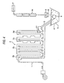
- Fig. 4 shows an example of a hot-dipping steel strip production apparatus of the invention. This example is a case that the support roll is removed, and the warp at the sink roll is corrected by the electromagnet.
- the support roll 7 in the molten zinc bath 5 in the conventional production apparatus shown in Fig. 1 is removed, and strain imparting device 21 is installed in a controlling cooled reactor 2d in the annealing furnace 2 and shape correcting means 9 for correcting the shape of the steel strip 1 using the electromagnet in the noncontact manner is installed immediately after the wiper 8.
- the strain imparting device 21 may be installed in the snout 3 portion at 450 to 650°C, when the device is installed in the controlling cooled reactor 2d in the annealing furnace 2, the temperature of the steel strip 1 is more easily controlled to 450 to 650°C. More preferably, the steel strip 1 is imparted with the strain at 500 to 550°C.
- the strain is preferably imparted at 500°C or more.
- the strain may imparted in the molten zinc bath 5 or imparted after the steel strip being drawn up from the molten zinc bath 5 only for preventing the buckling, since problems such as the uneven coatingweight of the molten zinc in the chatter mark pattern, push flaw, and plating separation occur, the strain impartation needs to be performed at an upstream side of the molten zinc bath 5.
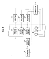
- Fig. 5 shows an example of the shape correcting means.
- the shape correcting means comprises a position sensors 10 that measure distances to the surface of the steel strip 1 moving upward in the figure; a controller 11 that receives a signal from the position sensors 10 and outputs a control signal; amplifiers 12 that amplify the control signal; and electromagnets 13 that exert sucking force on the steel strip 1 according to the amplified control signal and transforms the steel strip 1.
- the electromagnets 13 are installed plurally in a lateral direction of the steel strip 1, and disposed on both sides of the steel strip 1 in pairs.
- the electromagnets 13 exert the sucking force one-directionally on the steel strip 1, by disposing the electromagnets on the both sides of the steel strip 1 in pairs, a sucking direction of the steel strip 1 can be selected and the warp of the steel strip 1 can be corrected.
- the lateral warp of the steel strip 1 has a C-section as shown in Fig. 2, therefore the electromagnets 13 are disposed at three points in the lateral direction of the steel strip 1 (both edges and center). Since interference among respective position sensors 10 and among respective electromagnets 13 at the three points is not so large, each of them can be constituted using an independent control system.
- the sucking force of the electromagnets 13 disposed on the both sides of the steel strip 1 in pairs is controlled by the controller 11 according to the signal from the position sensors 10 that measure the distance to the surface of the steel strip 1, the warp of the steel strip 1 drawn up from the molten zinc bath 5 can be corrected.
- the shape correcting means 9 which is disposed immediately after the wiper 8, performs better control as it is closer to the wiper 8, when an alloying furnace, a touch roll, and a spangle adjustor are installed, it may be installed before the spangle adjustor.
- the means 9 When the means 9 is installed immediately before the wiper 8, while it performs better control as it is closer to the wiper 8, it may be installed between the molten zinc bath 5 and the wiper 8 in an actual line.
- the strain imparting device 21 is installed at a downstream side of the point where the steel strip 1 arrives at the maximum temperature. Since the steel strip 1 is heated to the maximum temperature of 650 to 900°C in a soaking pit 2b of the annealing furnace 2, if the strain imparting device 21 is installed at an upstream side of the point where the steel strip 1 arrives at the maximum temperature, the effect of imparting the strain is lost, and the buckling can not be prevented.
- the strain imparting device 21 that the plastic strain is imparted such that the surface residual plastic strain is 0.1% or more as described above, to this end, the strain needs to be imparted more than 0.1%, more preferably not less than 0.3% and not more than 1.5% in the amount of the surface plastic strain.
- an outer diameter of the roll is selected such that the radius of curvature of the steel strip 1 imparted by at least one roll is 400 mm or less, and the steel strip 1 is bent with the pushing amount of the roll being controlled.
- at least one roll having an outer diameter of 800 mm or less needs to be used.
- the bending can be achieved in a method of controlling the pushing amount such that the steel strip 1 winds around the roll having an outer diameter of 800 mm sufficiently, or a method of controlling the pushing amount using a roll having an outer diameter of 400 mm.
- the pushing amount of the roll is different depending on material or thickness of the steel strip 1.
- the pushing amount of the roll can be increased, or a roll having a small outer diameter can be used.
- the outer diameter of the roll is preferably 400 mm or less.
- a roll having an outer diameter of more than 800 mm such as a hearth roll, which is generally installed in the vertical type annealing furnace 2, is not used as the roll for imparting the plastic strain.
- the effect of imparting the strain is higher in the case that the number of the rolls is one.
- the strain may be imparted dividedly in a plurality of rolls, the effect is saturated even in 6 ormore rolls, which is disadvantageous in a point of facility cost or facility maintenance, therefore the number of rolls is preferably 1 to 5.
- the number of the rolls is one, the amount of impartable surface plastic strain can not be significantly increased, therefore more preferably, the actual number of rolls is made to be 2 to 3.
- each of rolls may have a different outer diameter.
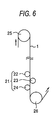
- Fig. 6 shows an example of the strain imparting device.
- the strain imparting device 21, which is provided at an intermediate position between hearth rolls 25 and 26 in the controlling cooled reactor 2d comprises three rolls 22, 23, and 24.
- the three rolls are disposed alternatively on both sides of the steel strip 1, and each of them is freely movable independently in a substantially perpendicular direction to the path line.
- At least one of the three rolls 22, 23, and 24 is pushed in a direction substantially perpendicular to the path line, thereby the steel strip 1 is imparted with the surface plastic strain.
- the amount of the imparted surface plastic strain is determined by the radius of curvature of the steel strip 1 that has been bent, and the curvature is determined by a space between adjacent rolls along the path line, the outer diameter, and the pushing amount of the roll.
- the number of rolls is not limited to three and may be varied within a range from 1 to 5.
- the roll is preferably disposed near the hearth roll 26.
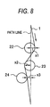
- Figs. 7A to 7D show examples of strain impartation by the three rolls in Fig. 6.
- Fig. 7A the rolls 22 and 24 are disposed substantially on the path line, and the roll 23 is pushed in a direction substantially perpendicular to the path line, thereby surface plastic strain is imparted to the steel strip 1.
- the roll 24 is disposed substantially on the path line, and the rolls 22 and 23 are pushed oppositely in a direction substantially perpendicular to the path line, thereby the plastic strain is imparted to the surface of the steel strip 1.
- the strain imparted by the roll 24 at the most downstream side is determined according to a relative positional relationship between the roll 24 and the rolls 22, 23 at an upstream side, when the pushing amount of the rolls 22, 23 is large, the roll 23 is sometimes displaced from the path line. For example, as shown in Fig.
- roll is on the path line
- the roll surface locates at a position where the roll surface contacts with the path line.
- the surface residual plastic strain which is remained on the surface of the steel strip 1 at the point when the steel strip arrives at the sink roll in the molten zinc bath, is more important for preventing the buckling and the warp by the sink roll than the surface plastic strain, which is imparted to the steel strip by the strain imparting device such as the device in Fig. 6.
- the strain imparting device such as the device in Fig. 6.
- the plastic strain is scarcely lost at a downstream side of the molten zinc bath at about 450°C.
- alloying treatment for about 3 sec at 550°C is performed at the downstream side of the molten zinc bath. Accordingly, if the amount of residual strain is controlled at the sink roll after which the plastic strain is not lost, the buckling or warp can be prevented more effectively.
- the values of a and b are obtained by imparting a fixed amount of strain to a certain type of steel, and measuring the amount of strain after heat treatment for a fixed time at a certain temperature. Meanwhile, a concerns with the activation energy for diffusion of the strain, and b concerns with the diffusion coefficient.
- Table 1 shows a calculation example of the surface residual plastic strain A when A0 is fixed to 0.1, and t and T are varied.
- the steel strip when surface plastic strain of 1.5% or less is imparted to a steel strip at 650°C or more, the steel strip is preferably moved to the sink roll within 10 sec; when surface plastic strain of not less than 0.35% and not more than 1.5% is imparted to a steel strip at not less than 600°C and less than 650°C, the steel strip is preferably moved to the sink roll within 40 sec; and when surface plastic strain of not less than 0.3% and not more than 1.5% is imparted to a steel strip at not less than 450°C and less than 600°C, the steel strip is preferably moved to the sink roll within 120 sec.
- the surface residual plastic strain of the steel strip by the sink roll can be securely made to be 0.1% or more.
- the inventors have obtained a finding that even if same amount of strain is imparted, there are cases with and without occurrence of the buckling depending on the elapsed time after the strain impartation to the roll where the buckling essentially tends to occur, such as the support roll located at the downstream side of the sink roll. From this, it is considered that as the dislocation increases, which is remained in the steel strip immediately before the temperature range in which the buckling occurs, the buckling is prevented more advantageously. It is also understood from that freely movable dislocation (movable dislocation) increases in proportion to the amount of the residual strain, and the movable dislocation is responsible for continuous plastic transformation (or the buckling is hard to occur).
- the elongation percentage imparted to the steel strip in JP-A-10-130801 is not the amount of strain at the position where the buckling occur, in certain elapsed time from imparting strain or temperature of the steel strip, no strain remains at a point when the buckling occurs, therefore the buckling can not be prevented.
- the elongation percentage is the average strain amount in a thickness direction, and is not surface plastic strain of the steel strip that is effective for preventing the buckling, the buckling can not be securely prevented by the elongation percentage.
- the lateral warp of the steel strip 1 occurred at the wiper 8 portion in Fig. 4 is influenced most largely by the residual strain given by the roll at the downstream side. Therefore, the lateral warp is influenced most largely by the plastic strain given by the sink roll 6, next influenced largely by the plastic strain given by the roll at the most downstream side of the strain imparting device 21.
- the direction of the warp of the steel strip 1 is determined according to which plastic transformation of tension or compression is given to the both sides of the steel strip 1. Accordingly, it is enough to reduce the warp of the steel strip 1 occurred at the wiper 8 portion that the direction of the plastic strain given by the sink roll 6 is inverted with the direction of the plastic strain given by the roll at the most downstream side of the strain imparting device 21.
- the required pushing amount of the roll is determined as follows. In addition to relations between conditions of the steel strip 1 such as material or thickness, and temperature, spaces along the path line among respective rolls, the outer diameter, and the pushing amount, and the amount of surface plastic strain, relations between the above conditions of the steel strip 1 and the amount of warp at the wiper 8 portion are previously obtained, and a correlation table between the above conditions of the steel strip 1 and the pushing amount of the roll, which is compatible with the prevention of the lateral warp by the amount of the surface plastic strain, is previously prepared, and the pushing amount of the roll by which the buckling can be prevented is determined based on the correlation table. Also, when the outer diameter of the sink roll 6 is increased, such correlation table is prepared.
- JP-A-2000-204460 describes the correction of the warp of the metal strip using a pushing roll.
- the support roll is provided in the molten metal bath, a problem due to the support roll occurs.
- the warp of the metal strip is corrected by combined use of the support roll with the pushing roll, therefore it is essentially different from the warp correction method of the invention.
- the sink roll is not present in the molten metal bath, it is difficult to impart tension force stably to the metal strip, and surface plastic strain can not be imparted stably as required.
- the outer diameter of the sink roll may be larger than that in the case that the support roll is installed.
- Fig. 9 shows a relation between the outer diameter of the sink roll and the amount of lateral warp of the steel strip.
- the amount of warp is measured in the wiper portion of the steel strip 1200 mm in width, in which the sign is "+" when the warp is convex to a sink roll side, and "-" when it is convex to a side opposite to the sink roll side.
- the outer diameter of the sink roll is preferably made to be 850 mm or more.
- the sink roll is preferably arranged such that a distance between the top of the roll and a surface of the molten zinc bath is 50 to 400 mm. This is because when the distance is less than 50 mm, the bath surface is stirred by the rotation of the sink roll and a large amount of top dross is produced, and when it is more than 400 mm, a deep molten zinc bath chamber is required, causing increase in facility cost.
- the steel strip 1 is imparted with the plastic strain by the strain imparting device 21, and then drawn into the molten zinc bath 5 through the snout 3, and then turned around by the sink roll 6, and then drawn up from the molten zinc bath 5, and then plating weight is controlled by the wiper 8, and then the steel strip 1 is cooled directly or after alloying of the plating layer in alloying furnaces 14, thereby a desired galvanized steel strip is formed.
- a galvanized steel strip can be produced, in which the buckling or splash does not occur, and the plating weight is laterally uniform, in addition, since the support roll is removed from the molten zinc bath in the example in Fig. 4, problems such as quality defects due to the support roll and shutdown of equipment for changing the rolls are solved.
- a spangle adjustor may be provided instead of the alloying furnace 14 for spangle adjustment.
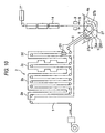
- Fig. 10 shows another example of the hot-dipping steel strip production apparatus of the invention.
- the example is a case that the support roll is removed, and the warp at the sink roll is corrected using the electromagnet, in addition, an enclosing member is provided.
- the enclosing member 27 is opposed to a face of the steel strip 1 drawn into the molten metal bath 5; provided such that it encloses the face of the steel strip 1; divides the molten zinc bath 5 into an upper area 5A and a lower area 5B; and permits flow of the molten zinc between the upper area 5A and the lower area 5B. That is, the enclosing member 27 is a molten zinc chamber having an opened top provided in the molten zinc bath 5. Since the top is opened, the molten zinc in the chamber is flown out a long with movement of the steel strip 1 and molten zinc is flown in from an outside of the chamber, and thus flow of the molten zinc is formed.
- An upper end of the enclosing member 27 is located below a bath surface of the molten zinc bath 5, and an end 27b of the enclosing member 27 at a drawing-up side of the steel strip is located above a shaft core of the sink roll 6.
- the enclosing member 27 is disposed such that a distance to an underside of the steel strip 1 is at minimum directly under the sink roll 6.
- the enclosing member 27 is made of stainless steel that may stand use of the high-temperature molten zinc.
- a leg-like supporting member (not shown) is installed on a lower portion of the enclosing member 27, and the enclosing member 27 is placed can be easily disposed on a bottom of the molten zinc bath chamber 4 through the supporting member. Accordingly, the enclosing member 27 can be easily disposed in the molten zinc bath chamber 4 and easily removed out of the molten zinc bath chamber 4.
- Arrows around the enclosing member 27 in Fig. 10 show flow of the molten zinc.
- the black arrows show molten zinc with dross
- the white arrows show molten zinc in which the dross is precipitated and removed and thus cleaned.
- the molten zinc in the upper area 5A of the enclosing member 27 is flowed out beyond the end 27b of the enclosing member 27 at a drawing-up side of the steel strip 1 into the lower area 5B along with the movement of the steel strip 1.
- the flow of the molten zinc is maintained even in an area where the steel strip is not passing.
- molten zinc containing the flowed-in fine dross flows downward along a sidewall 4a at a drawing-up side of the steel strip 1 of the molten zinc bath chamber 4, and then flows along the enclosing member 27 to a drawing-in side (snout 3 side) of the steel strip 1 of the molten zinc bath chamber 4. Since the lower area 5B has a large capacity compared with the upper area 5A, and is not directly influenced by the accompanying flow of the steel strip 1 in the upper area 5A, the molten zinc flows slowly.
- the dross contained in the molten zinc precipitates on the bottom of the molten zinc bath chamber 4.
- the dross precipitated and deposited on the bottom of the molten zinc bath chamber 4 gathers and grows into large dross 16 that affects on quality of the steel strip 1. Since flow is slow in the lower portion 5B, the large dross 16 deposited on the bottom of the molten zinc bath chamber 4 is hardly coiled up even if the conveyance speed of the steel strip 1 is varied, or even if the dross is coiled up, the dross promptly precipitates on the bottom of the molten zinc bath chamber 4.
- the molten zinc bath 5 is clean in the area at the drawing-in side of the steel strip 1 in the lower area 5B. Particularly, a supernatant bath on top of the bath surface is further clean, and the large dross 16 that influences on the quality of the steel strip 1 does not float.
- the cleaned supernatant bath in the molten zinc bath 5 flows into the upper area 5A beyond the end 27a of the enclosing member 27at the drawing-in side of the steel strip 1 with the accompanying flow of the steel strip 1.
- the steel strip 1 is drawn from the snout 3 into the molten zinc bath 5, turned around in the upper area 5A by the sink roll 6 with accompanying the cleaned molten zinc bath 5, and then drawn up from the molten zinc bath 5. While the steel strip 1 is drawn into the molten zinc bath 5 and drawn up from the molten zinc bath 5, the dross 16 influencing on the quality is not present in the movement area of the steel strip 1, therefore the steel strip 1 without the adhered dross can be produced.
- the enclosing member 27 is preferably installed such that the proximal distance to the steel strip 1 is 50 to 400 mm. This is because when the distance is less than 50 mm, the member may contact with the steel strip 1 due to thermal deformation, or positioning is difficult in installing the enclosing member 27, and when the distance is more than 400 mm, an area is generated in the enclosing member 27, in which influence of the accompanying flow of the steel strip 1 does not appear, and the dross produced in the enclosing member 27 can not be discharged into the lower area 5B and deposits within the enclosing member 27.
- the enclosing member 27 may be installed such that its upper end is above the surface of the molten zinc bath. In this case, in a portion of the end 27a of the enclosing member 27 on the bath surface at the drawing-in side of the steel strip 1, or in a portion in the bath close to the bath surface, an opening for flowing the molten zinc in the lower area 5B into the upper area 5A is installed. Alternatively, in a portion of the end 27b of the enclosing member 27 on the bath surface at the drawing-up side of the steel strip 1, or in a portion in the bath close to the bath surface, an opening for flowing out the molten zinc in the upper area 5A into the lower area 5B may be installed.
- the enclosing member 27 when the enclosing member 27 is above the bath surface, operation of removing the top dross produced on the bath surface in the enclosing member 27 out of the molten zinc bath chamber 4 is complicated; and the top dross adheres on the enclosing member 27, the accompanying flow with the steel strip 1 may flow out the molten zinc in the upper area 5A into the lower area 5B, and may flow the clean molten zinc from the lower area 5B into the upper area 5A; therefore the upper end of the enclosing member 27 is preferably installed below the bath surface.
- the upper end of the enclosing member 27 is less than 100 mmbelow the bath surface, the accompanying flow with the steel strip 1 stirs the bath surface and thus increases the amount of produced top dross, therefore the upper end is preferably made to be not less than 100 mm below the bath surface.
- the upper end of the enclosing member 27 must be above the shaft core of the sink roll 6, more preferably above the utmost portion of the sink roll 6.
- the apparatus shown in Fig. 10 is excellent because of the function of suppressing the dross adhesion, therefore even if the conveyance speed of the steel strip 1 is not decreased, or even if production efficiency is not reduced, a high-quality galvanized steel strip without the dross adhesion can be produced.
- the molten zinc in the molten zinc bath chamber 4 is flowed from the drawing-in side of the steel strip 1 to the drawing-up side of the steel strip 1 with the accompanying flow with the steel strip 1, and flowed out into the lower area 5B beyond the end 27b of the enclosing member 27 at the drawing-up side of the steel strip 1.
- the molten zinc flows downward along the sidewall 4a of the molten zinc bath chamber 4 at the drawing-up side of the steel strip 1, and flows into the drawing-in side of the steel strip 1 through an underside portion and a sideface of the enclosing member 27, or flows in a direction opposite to the direction in the upper area 5A.
- the molten zinc circulates between the upper area 5A and the lower area 5B, however, driving force of the molten zinc circulation is caused by the accompanying flow with the passing steel strip 1, and equipment for the circulation such as a pump is unnecessary, therefore there is an advantage that facility can be simple and inexpensive.
- the dross deposited on the bottom of the lower area 5B or the bottom of the molten zinc bath chamber 4 may be removed by removing the enclosing member 27 out of the molten zinc bath chamber 4, and then using conventionally known means.
- Fig. 11 shows another example of the hot-dipping steel strip production apparatus of the invention.
- This apparatus is an apparatus in which the shape correcting means 9 is removed from the apparatus in Fig. 4. Although both of the support roll and the shape correcting means are not present; if the roll 24 at the most downstream side of the strain imparting device 21 is disposed such that the roll contacts with the surface opposite to the surface on which the sink roll 6 contacts with the metal strip 1 as shown in Fig. 6 and the pushing amount of the roll is controlled, the lateral warp of the steel strip 1 can be made substantially zero in the wiper 8 portion.
- the pushing amount of the roll 24 needs to be controlled such that the amount of the surface residual plastic strain of the metal strip 1 caused by the roll 24 is smaller than the amount of the surface plastic strain of the metal strip 1 caused by the sink roll, however, when the amount is too small (the residual amount is 0.05% or less), the warp given by the sink roll can not be cancelled.
- Fig. 12 shows another example of the hot-dipping steel strip production apparatus of the invention.
- This apparatus is an apparatus in which the enclosing member 27 shown in Fig. 10 is added in the molten metal bath chamber 4 in the apparatus in Fig. 11.
- the enclosing member 27 provides a merit that the dross adhesion is more perfectly prevented compared with the apparatus in Fig. 11.
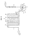
- Fig. 13 shows another example of the hot-dipping steel strip production apparatus of the invention. This example is a case with employing the support roll and without employing the electromagnet.
- the support roll 7 (7a, 7b) is added in the molten metal bath chamber 4 in the apparatus in Fig. 11. Therefore, the warp to be occurred at the sink roll 6 can be cancelled and the lateral warp of the steel strip 1 at the wiper 8 portion can be reduced, in addition, the strain imparting function of the support roll 7 is displayed, thereby the buckling can be suppressed even in the case of a steel type or an operation condition in which the buckling is apt to occur. At that time, since the warp correction by the support roll 7 need not be considered, the pushing amount can be reduced. Therefore, increase of defects by pushing the dross, or increase of maintenance cost due to roll abrasion can be prevented.
- the strain imparting device 21 need not be operated in such a condition that the warp occurred at the sink roll 6 is cancelled in any case. That is, just by adding the strain imparting function of the strain imparting device 21 to the warp correcting function and strain imparting function of the support roll 7 , a condition can be selected, wherein the buckling scarcely occur, while the problems due to the support roll 7 occur as ever.
- a hot-rolled steel strip that has been descaled after hot rolling and a cold-rolled steel strip obtained by cold-rolling the hot-rolled steel strip can be used.
- the galvanized steel strip using the cold-rolled steel strip as a material is often used for an application required for good surface appearance such as an automobile outside plate, and the galvanized steel strip produced in the method of the invention is suitable for such application.
- cold-rolled steel strips 0.75 mm in thickness and 1200 mm in width which are produced using steels a to e having chemical compositions shown in Table 2, were annealed in line speed of 120 mpm, tensile force of 2 kg/mm 2 , and temperature of 850°C, and then imparted with strain in conditions shown in table 3 by the strain imparting device, and then immersed in the molten zinc bath at 460°C, and then drawn up from the molten zinc bath; and gas pressure of the wiper was adjusted such that the coating weight for one side of the steel strip is 45 g/m 2 while the shape of steel strip was corrected in a noncontact manner by the shape correcting means; and then temper roll ing having a rolling rate of 1.2% was done, consequently galvanized steel strips 1 to 15 were produced.
- the galvanized steel strip 1 was not imparted with strain by the strain imparting device, and had the tensile properties before the temper rolling of upper yield point of 25 kg/mm 2 , lower yield point of 22 kg/mm 2 , and yield point elongation of 4.3%, and the temperature at which the yield point elongation disappeared (threshold temperature T1) was 440°C.
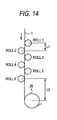
- the strain imparting device As the strain imparting device, a device having six rolls (rolls 1 to 6) shown in Fig. 14 was used, and the imparted strain amount was varied according to the following conditions. Each of intervals L1 among adj acent rolls along the path line was 300 mm, and an interval L2 between the roll 6 and the hearth roll 26 was 1000 mm. The outer diameter of the hearth roll 26 was 1000 mm.
- Rolls 1, 2, 4, and 5 were not used, and a roll having an outer diameter of 1000 mm as the roll 3 and a roll having an outer diameter of 100 mm as the roll 6 are disposed, and the roll 6 was pushed in a direction substantially perpendicular to the path line, thereby the strain was imparted.
- the roll 6 was reinforced by a backup roll having an outer diameter of 400 mm from a point of roll stiffness.
- a case of 3 rolls Rolls 1 to 3 were not used, the roll 6 was disposed on the path line, and the roll 4 and the roll 5 were pushed into displaced positions from the path line as shown in Fig. 7B, thereby the strainwas imparted.
- a roll having an outer diameter of 250 mm or outer diameter of 1000 mm was used for the rolls 4 to 6.
- respective rolls were reinforced by the backup roll having the outer diameter of 400 mm from the point of roll stiffness.
- a case of 5 rolls The roll 1 was not used, three rolls 2, 4, and 6 having the outer diameter of 250 mm were disposed on the path line, and in respective middle positions among these rolls, the rolls 3 and 5 were disposed oppositely across the steel strip, and the rolls 3 and 5 were pushed in a direction substantially perpendicular to the path line, thereby the strain was imparted.
- a case of 6 rolls The rolls 1 to 6 having the outer diameter of 250 mm were disposed as shown in Fig. 14, and the rolls 1, 3, and 5 were pushed in a direction substantially perpendicular to the path line, thereby the strain was imparted.
- the diameter of the sink roll is 950 mm.
- the shape correcting means shown in Fig. 5 is installed at a position 20 mm away from the path line.
- electric current for the electromagnet is controlled according to the amount of transformation of the steel strip measured by a laser displacement meter in order to eliminate the warp of the steel strip in the wiper portion.
- the warp is not corrected by the shape correcting means.
- the enclosing member installed in the molten zinc bath has a shape accommodated to the sink roll, and has a minimum space of 100 mm to the steel strip.
- the enclosing member was removed from the apparatus in Fig. 10, and a galvanized steel strip 16 was produced in addition to such steel strips 1 to 15 using the steel d in Table 2.
- a galvanized steel strip 17 was produced using the steel e in Table 2 and using the conventional production apparatus shown in Fig. 1, in which the support roll is present in the molten zinc, and the strain imparting device, shape correcting means, or enclosing member is not present.
- the level of the buckling a press test simulated the press of an automobile door panel was conducted, and then the buckling was visually observed and evaluated in 6 stages of 0 to 5 according to the level of the buckling.
- the buckling level is best at 0 (no occurrence), and becomes worse as the number increases. It is desirable that the buckling level is not more than 1 in the application of the automobile outside panel, and not more than 2 in the application of the automobile inside panel.
- Table 3 shows results of the buckling level.
- the lateral deviation of the coating weight was about ⁇ 5 g/m 2
- the lateral deviation of the coating weight was about ⁇ 10 g/m 2
- presence of the dross on the surface of the steel strip was confirmed using a 300 mm square sample, as a result the dross was not confirmed in either condition.
- the buckling level was 5, or bad
- the steel strips 2 to 15, in which the strain imparting conditions are within the scope of the invention have a buckling level of not more than 2, which is slight in such a degree that the buckling defect is not a practical issue.
- the press test of an automobile door was performed, as a result no defect due to the buckling was found for the buckling level 0 and 1, and the defects were extremely slight for the buckling level 2.
- the lateral deviation of the coatingweight was about ⁇ 5 g/m 2 , and a surface of the steel sheet was observed using the 300 mm square sample, as a result the number of the dross was about5. The buckling defect was not found.
- the lateral deviation of the coating weight was about ⁇ 10 g/m 2
- a surface of the steel sheet was observed using the 300 mm square sample, as a result the number of the dross was about 5.
- the buckling defect in the buckling level of 4 was found over the entire surface of the steel strip, and further deteriorated buckling defect was confirmed after the press test.
- the strain impartation was set such that the strain was able to cancel the warp at the sink roll, however, the deviation of the coating weight was about ⁇ 10 g/m 2 in each roll, which was almost equal to the conventional one. It is known from that that there is a similar warp correction effect in the example of the invention as in the conventional support roll.
Landscapes
- Chemical & Material Sciences (AREA)
- Engineering & Computer Science (AREA)
- Materials Engineering (AREA)
- Mechanical Engineering (AREA)
- Metallurgy (AREA)
- Organic Chemistry (AREA)
- Chemical Kinetics & Catalysis (AREA)
- Physics & Mathematics (AREA)
- Thermal Sciences (AREA)
- Crystallography & Structural Chemistry (AREA)
- Coating With Molten Metal (AREA)
Applications Claiming Priority (7)
| Application Number | Priority Date | Filing Date | Title |
|---|---|---|---|
| JP2002267890A JP2004107681A (ja) | 2002-09-13 | 2002-09-13 | 溶融めっき金属帯の製造方法および製造装置 |
| JP2002267890 | 2002-09-13 | ||
| JP2002267892A JP4221978B2 (ja) | 2002-09-13 | 2002-09-13 | 金属帯製造設備内での腰折れ発生を防止する金属帯の製造方法 |
| JP2002267891A JP4389435B2 (ja) | 2002-09-13 | 2002-09-13 | 溶融めっき金属帯の製造方法および製造装置 |
| JP2002267892 | 2002-09-13 | ||
| JP2002267891 | 2002-09-13 | ||
| PCT/JP2003/011478 WO2004024974A1 (fr) | 2002-09-13 | 2003-09-09 | Procede et dispositif de production d'une courroie metallique revetue par immersion a chaud |
Publications (1)
| Publication Number | Publication Date |
|---|---|
| EP1538233A1 true EP1538233A1 (fr) | 2005-06-08 |
Family
ID=31998765
Family Applications (1)
| Application Number | Title | Priority Date | Filing Date |
|---|---|---|---|
| EP03795324A Withdrawn EP1538233A1 (fr) | 2002-09-13 | 2003-09-09 | Procede et dispositif de production d'une courroie metallique revetue par immersion a chaud |
Country Status (7)
| Country | Link |
|---|---|
| US (1) | US7617583B2 (fr) |
| EP (1) | EP1538233A1 (fr) |
| KR (1) | KR100704692B1 (fr) |
| CN (1) | CN100471980C (fr) |
| CA (1) | CA2479031C (fr) |
| TW (1) | TWI294919B (fr) |
| WO (1) | WO2004024974A1 (fr) |
Cited By (1)
| Publication number | Priority date | Publication date | Assignee | Title |
|---|---|---|---|---|
| EP1860206A1 (fr) * | 2006-05-22 | 2007-11-28 | Abb Research Ltd. | Procédé et appareillage pour stabiliser le positionnement latéral d'un élément métallique allongé |
Families Citing this family (14)
| Publication number | Priority date | Publication date | Assignee | Title |
|---|---|---|---|---|
| SE527507C2 (sv) * | 2004-07-13 | 2006-03-28 | Abb Ab | En anordning och ett förfarande för stabilisering av ett metalliskt föremål samt en användning av anordningen |
| US8062711B2 (en) * | 2005-03-24 | 2011-11-22 | Abb Research Ltd. | Device and a method for stabilizing a steel sheet |
| CN100357482C (zh) * | 2005-08-05 | 2007-12-26 | 侯平 | 金属材料制品的镀塑方法 |
| MX2010002049A (es) * | 2007-08-22 | 2010-05-03 | Sms Siemag Ag | Procedimiento e instalación de refinamiento por inmersión en baño fundido para la estabilización de banda de una banda provista de un recubrimiento y conducida entre toberas rascadoras en una instalación de refinamiento por inmersión en baño fundido. |
| JP5211642B2 (ja) * | 2007-10-31 | 2013-06-12 | Jfeスチール株式会社 | 溶融亜鉛めっき鋼板の製造設備及び溶融亜鉛めっき鋼板の製造方法 |
| JP5505430B2 (ja) * | 2012-01-17 | 2014-05-28 | Jfeスチール株式会社 | 鋼帯の連続焼鈍炉及び連続焼鈍方法 |
| US9551056B2 (en) * | 2012-05-10 | 2017-01-24 | Nippon Steel & Sumitomo Metal Corporation | Steel sheet shape control method and steel sheet shape control apparatus |
| WO2014199923A1 (fr) * | 2013-06-11 | 2014-12-18 | 新日鐵住金株式会社 | Produit estampé à chaud et procédé pour la production d'un produit estampé à chaud |
| CN103710657A (zh) * | 2014-01-02 | 2014-04-09 | 苏州赛历新材料科技有限公司 | 一种新型焊带刮刀装置 |
| DE102015108334B3 (de) * | 2015-05-27 | 2016-11-24 | Thyssenkrupp Ag | Vorrichtung und Verfahren zur verbesserten Metalldampfabsaugung bei einem kontinuierlichen Schmelztauchverfahren |
| EP3564403B1 (fr) * | 2017-02-20 | 2020-11-18 | Primetals Technologies Japan, Ltd. | Dispositif de correction de courbure de tôle, équipement de placage de métal fondu et procédé de correction de courbure de tôle |
| US11384419B2 (en) * | 2019-08-30 | 2022-07-12 | Micromaierials Llc | Apparatus and methods for depositing molten metal onto a foil substrate |
| IT202000016012A1 (it) * | 2020-07-02 | 2022-01-02 | Danieli Off Mecc | Apparato di correzione della planarità di un nastro metallico e relativo metodo di correzione |
| CN116121682A (zh) * | 2023-01-08 | 2023-05-16 | 首钢京唐钢铁联合有限责任公司 | 镀铝锌产品锌花不均的优化方法及相关设备 |
Family Cites Families (23)
| Publication number | Priority date | Publication date | Assignee | Title |
|---|---|---|---|---|
| US3499418A (en) * | 1966-12-01 | 1970-03-10 | Nat Steel Corp | Continuous metallic strip hot-dip metal coating apparatus |
| US3808033A (en) * | 1970-01-27 | 1974-04-30 | Nat Steel Corp | Continuous metallic strip hot-dip metal coating apparatus |
| US4153006A (en) * | 1975-04-17 | 1979-05-08 | Armco Steel Corporation | Apparatus for finishing molten metallic coatings |
| JPS5641365A (en) * | 1979-09-12 | 1981-04-18 | Nisshin Steel Co Ltd | Continuous hot dipping apparatus |
| US5023113A (en) * | 1988-08-29 | 1991-06-11 | Armco Steel Company, L.P. | Hot dip aluminum coated chromium alloy steel |
| JPH0794704B2 (ja) | 1990-11-27 | 1995-10-11 | 住友金属工業株式会社 | 合金化溶融亜鉛めっき鋼板の製造方法 |
| JPH04272162A (ja) * | 1991-02-27 | 1992-09-28 | Sumitomo Metal Ind Ltd | 溶融金属めっき鋼板の製造装置および方法 |
| JPH05156417A (ja) * | 1991-11-29 | 1993-06-22 | Sumitomo Heavy Ind Ltd | 溶融金属メッキ方法およびそれに用いる焼鈍炉 |
| JPH05171385A (ja) * | 1991-12-26 | 1993-07-09 | Kawasaki Steel Corp | 鋼帯の連続溶融亜鉛めっき方法および装置 |
| JP2928454B2 (ja) * | 1994-03-31 | 1999-08-03 | 川崎製鉄株式会社 | 連続溶融金属めっき装置 |
| JP3695759B2 (ja) * | 1995-02-24 | 2005-09-14 | 日新製鋼株式会社 | 溶融アルミニウムめっき鋼板およびその製造方法ならびに合金層制御装置 |
| JPH10130801A (ja) | 1996-10-25 | 1998-05-19 | Sumitomo Metal Ind Ltd | 表面品質に優れた溶融めっき鋼板の製造方法 |
| US6093452A (en) * | 1997-02-25 | 2000-07-25 | Nkk Corporation | Continuous hot-dip coating method and apparatus therefor |
| JPH11100651A (ja) | 1997-07-30 | 1999-04-13 | Kawasaki Steel Corp | 連続溶融金属めっき装置 |
| JP2000204460A (ja) | 1999-01-12 | 2000-07-25 | Kawasaki Steel Corp | 溶融金属めっき方法および装置 |
| JP2000256884A (ja) * | 1999-03-08 | 2000-09-19 | Sumitomo Heavy Ind Ltd | 金属板の酸洗方法およびそれに用いる酸洗装置 |
| TW500827B (en) * | 1999-08-06 | 2002-09-01 | Sms Demag Ag | Process and installation for hot galvanizing of hot rolled steel strip |
| FR2816640B1 (fr) * | 2000-11-10 | 2003-10-31 | Lorraine Laminage | Installation de revetement au trempe a chaud et en continu d'une bande metallique |
| RS50049B (sr) * | 2000-11-10 | 2008-11-28 | Sollac, | Uređaj oblaganja sa namakanjem metalne trake |
| JP2002339051A (ja) | 2001-03-15 | 2002-11-27 | Nkk Corp | 溶融めっき金属帯の製造方法及び製造装置 |
| WO2002077313A1 (fr) * | 2001-03-15 | 2002-10-03 | Nkk Corporation | Procede de production d'une bande metallique par immersion a chaud et dispositif correspondant |
| DE10146791A1 (de) * | 2001-09-20 | 2003-04-10 | Sms Demag Ag | Verfahren und Vorrichtung zum Beschichten der Oberfläche von strangförmigem metallischem Gut |
| DE10148158A1 (de) * | 2001-09-28 | 2003-04-17 | Sms Demag Ag | Verfahren zur Schmelztauchveredelung mit umgekehrtem Bandlauf |
-
2003
- 2003-09-09 EP EP03795324A patent/EP1538233A1/fr not_active Withdrawn
- 2003-09-09 CN CNB038093952A patent/CN100471980C/zh not_active Expired - Fee Related
- 2003-09-09 CA CA002479031A patent/CA2479031C/fr not_active Expired - Fee Related
- 2003-09-09 KR KR1020047016789A patent/KR100704692B1/ko not_active Expired - Fee Related
- 2003-09-09 US US10/508,375 patent/US7617583B2/en not_active Expired - Fee Related
- 2003-09-09 WO PCT/JP2003/011478 patent/WO2004024974A1/fr not_active Ceased
- 2003-09-12 TW TW092125189A patent/TWI294919B/zh not_active IP Right Cessation
Non-Patent Citations (1)
| Title |
|---|
| See references of WO2004024974A1 * |
Cited By (1)
| Publication number | Priority date | Publication date | Assignee | Title |
|---|---|---|---|---|
| EP1860206A1 (fr) * | 2006-05-22 | 2007-11-28 | Abb Research Ltd. | Procédé et appareillage pour stabiliser le positionnement latéral d'un élément métallique allongé |
Also Published As
| Publication number | Publication date |
|---|---|
| US7617583B2 (en) | 2009-11-17 |
| CA2479031C (fr) | 2008-06-03 |
| WO2004024974A1 (fr) | 2004-03-25 |
| US20050115052A1 (en) | 2005-06-02 |
| CN100471980C (zh) | 2009-03-25 |
| KR20050014809A (ko) | 2005-02-07 |
| KR100704692B1 (ko) | 2007-04-10 |
| TW200404915A (en) | 2004-04-01 |
| CA2479031A1 (fr) | 2004-03-25 |
| TWI294919B (en) | 2008-03-21 |
| CN1650040A (zh) | 2005-08-03 |
Similar Documents
| Publication | Publication Date | Title |
|---|---|---|
| US7617583B2 (en) | Method for producing hot-dip coated metal belt | |
| US12221701B2 (en) | Welded member of galvanized steel sheets | |
| EP3219822B1 (fr) | Tôle d'acier haute résistance galvanisée à chaud au trempé et son procédé de production | |
| JP5304966B1 (ja) | 合金化溶融亜鉛めっき鋼板 | |
| CN102282280B (zh) | 钢板和表面处理钢板以及钢板和表面处理钢板的制造方法 | |
| KR101128316B1 (ko) | 연속 소둔 설비 | |
| EP3219821A1 (fr) | Tôle d'acier haute résistance galvanisée à chaud au trempé et son procédé de production | |
| WO2014199923A1 (fr) | Produit estampé à chaud et procédé pour la production d'un produit estampé à chaud | |
| US10927441B2 (en) | High-strength galvanized hot-rolled steel sheet and method for manufacturing same | |
| CN114901842A (zh) | 热压成型钢制品的方法及钢制品 | |
| CN115958059A (zh) | 一种锌基合金镀层热冲压成形钢的制备方法 | |
| US4296919A (en) | Apparatus for continuously producing a high strength dual-phase steel strip or sheet | |
| CN111295459A (zh) | 合金化热浸镀锌钢板的制造方法 | |
| JPH08246121A (ja) | 高加工性、高強度溶融亜鉛めっき鋼板の製造方法 | |
| JP3765270B2 (ja) | 溶融めっき金属帯の製造方法および製造装置 | |
| Jagannathan | Emerging technologies in the hot-dip coating of automotive sheet steel | |
| JP4428040B2 (ja) | 溶融めっき金属帯の製造方法 | |
| JP4389435B2 (ja) | 溶融めっき金属帯の製造方法および製造装置 | |
| JP2004107681A (ja) | 溶融めっき金属帯の製造方法および製造装置 | |
| JP4428039B2 (ja) | 溶融めっき金属帯の製造方法 | |
| JP2005097748A (ja) | 溶融めっき金属帯の製造方法及び製造装置 | |
| CA1136852A (fr) | Installation de production en continu de feuillards ou de toles d'acier | |
| KR20260068531A (ko) | 표면 조도가 우수한 고강도 도금강판 및 그 제조 방법 | |
| JPH03232952A (ja) | めっき層密着性の良好な溶融亜鉛めっき鋼板の製造方法 | |
| JP2002302315A (ja) | 非接触通板方向転換装置及び鋼帯の製造方法 |
Legal Events
| Date | Code | Title | Description |
|---|---|---|---|
| PUAI | Public reference made under article 153(3) epc to a published international application that has entered the european phase |
Free format text: ORIGINAL CODE: 0009012 |
|
| 17P | Request for examination filed |
Effective date: 20040930 |
|
| AK | Designated contracting states |
Kind code of ref document: A1 Designated state(s): AT BE BG CH CY CZ DE DK EE ES FI FR GB GR HU IE IT LI LU MC NL PT RO SE SI SK TR |
|
| RBV | Designated contracting states (corrected) |
Designated state(s): DE FR GB |
|
| STAA | Information on the status of an ep patent application or granted ep patent |
Free format text: STATUS: THE APPLICATION IS DEEMED TO BE WITHDRAWN |
|
| 18D | Application deemed to be withdrawn |
Effective date: 20070403 |