EP1538334B1 - Compresseur hermétique - Google Patents
Compresseur hermétique Download PDFInfo
- Publication number
- EP1538334B1 EP1538334B1 EP05003059A EP05003059A EP1538334B1 EP 1538334 B1 EP1538334 B1 EP 1538334B1 EP 05003059 A EP05003059 A EP 05003059A EP 05003059 A EP05003059 A EP 05003059A EP 1538334 B1 EP1538334 B1 EP 1538334B1
- Authority
- EP
- European Patent Office
- Prior art keywords
- suction
- hermetic
- type compressor
- refrigerant gas
- enclosed container
- Prior art date
- Legal status (The legal status is an assumption and is not a legal conclusion. Google has not performed a legal analysis and makes no representation as to the accuracy of the status listed.)
- Expired - Lifetime
Links
- 239000003507 refrigerant Substances 0.000 claims description 434
- 230000007246 mechanism Effects 0.000 claims description 48
- 239000000463 material Substances 0.000 claims description 18
- 229920001343 polytetrafluoroethylene Polymers 0.000 claims 1
- KKEYFWRCBNTPAC-UHFFFAOYSA-L terephthalate(2-) Chemical compound [O-]C(=O)C1=CC=C(C([O-])=O)C=C1 KKEYFWRCBNTPAC-UHFFFAOYSA-L 0.000 claims 1
- 238000005057 refrigeration Methods 0.000 description 231
- 230000000694 effects Effects 0.000 description 113
- 230000008859 change Effects 0.000 description 64
- 230000006872 improvement Effects 0.000 description 56
- 230000003247 decreasing effect Effects 0.000 description 52
- 230000006835 compression Effects 0.000 description 48
- 238000007906 compression Methods 0.000 description 48
- 230000010349 pulsation Effects 0.000 description 31
- 230000007423 decrease Effects 0.000 description 25
- 230000000630 rising effect Effects 0.000 description 18
- 238000004891 communication Methods 0.000 description 17
- 229910001285 shape-memory alloy Inorganic materials 0.000 description 17
- 230000003292 diminished effect Effects 0.000 description 15
- 230000005484 gravity Effects 0.000 description 13
- 239000000314 lubricant Substances 0.000 description 12
- 230000002265 prevention Effects 0.000 description 11
- 230000035939 shock Effects 0.000 description 11
- 230000001902 propagating effect Effects 0.000 description 7
- 230000003111 delayed effect Effects 0.000 description 5
- 238000010586 diagram Methods 0.000 description 5
- 239000004809 Teflon Substances 0.000 description 3
- 229920006362 Teflon® Polymers 0.000 description 3
- 230000002238 attenuated effect Effects 0.000 description 3
- 238000012937 correction Methods 0.000 description 3
- 238000005516 engineering process Methods 0.000 description 3
- 238000002474 experimental method Methods 0.000 description 3
- 238000006073 displacement reaction Methods 0.000 description 2
- 238000000034 method Methods 0.000 description 2
- 230000009467 reduction Effects 0.000 description 2
- 238000012546 transfer Methods 0.000 description 2
- LVGUZGTVOIAKKC-UHFFFAOYSA-N 1,1,1,2-tetrafluoroethane Chemical group FCC(F)(F)F LVGUZGTVOIAKKC-UHFFFAOYSA-N 0.000 description 1
- 238000004378 air conditioning Methods 0.000 description 1
- 238000001816 cooling Methods 0.000 description 1
- 238000010438 heat treatment Methods 0.000 description 1
- 230000008569 process Effects 0.000 description 1
- 230000001743 silencing effect Effects 0.000 description 1
Images






















Classifications
-
- F—MECHANICAL ENGINEERING; LIGHTING; HEATING; WEAPONS; BLASTING
- F04—POSITIVE - DISPLACEMENT MACHINES FOR LIQUIDS; PUMPS FOR LIQUIDS OR ELASTIC FLUIDS
- F04B—POSITIVE-DISPLACEMENT MACHINES FOR LIQUIDS; PUMPS
- F04B39/00—Component parts, details, or accessories, of pumps or pumping systems specially adapted for elastic fluids, not otherwise provided for in, or of interest apart from, groups F04B25/00 - F04B37/00
-
- F—MECHANICAL ENGINEERING; LIGHTING; HEATING; WEAPONS; BLASTING
- F04—POSITIVE - DISPLACEMENT MACHINES FOR LIQUIDS; PUMPS FOR LIQUIDS OR ELASTIC FLUIDS
- F04B—POSITIVE-DISPLACEMENT MACHINES FOR LIQUIDS; PUMPS
- F04B39/00—Component parts, details, or accessories, of pumps or pumping systems specially adapted for elastic fluids, not otherwise provided for in, or of interest apart from, groups F04B25/00 - F04B37/00
- F04B39/0027—Pulsation and noise damping means
- F04B39/0055—Pulsation and noise damping means with a special shape of fluid passage, e.g. bends, throttles, diameter changes, pipes
- F04B39/0072—Pulsation and noise damping means with a special shape of fluid passage, e.g. bends, throttles, diameter changes, pipes characterised by assembly or mounting
-
- F—MECHANICAL ENGINEERING; LIGHTING; HEATING; WEAPONS; BLASTING
- F04—POSITIVE - DISPLACEMENT MACHINES FOR LIQUIDS; PUMPS FOR LIQUIDS OR ELASTIC FLUIDS
- F04B—POSITIVE-DISPLACEMENT MACHINES FOR LIQUIDS; PUMPS
- F04B39/00—Component parts, details, or accessories, of pumps or pumping systems specially adapted for elastic fluids, not otherwise provided for in, or of interest apart from, groups F04B25/00 - F04B37/00
- F04B39/0027—Pulsation and noise damping means
- F04B39/0055—Pulsation and noise damping means with a special shape of fluid passage, e.g. bends, throttles, diameter changes, pipes
-
- F—MECHANICAL ENGINEERING; LIGHTING; HEATING; WEAPONS; BLASTING
- F04—POSITIVE - DISPLACEMENT MACHINES FOR LIQUIDS; PUMPS FOR LIQUIDS OR ELASTIC FLUIDS
- F04B—POSITIVE-DISPLACEMENT MACHINES FOR LIQUIDS; PUMPS
- F04B39/00—Component parts, details, or accessories, of pumps or pumping systems specially adapted for elastic fluids, not otherwise provided for in, or of interest apart from, groups F04B25/00 - F04B37/00
- F04B39/10—Adaptations or arrangements of distribution members
-
- F—MECHANICAL ENGINEERING; LIGHTING; HEATING; WEAPONS; BLASTING
- F04—POSITIVE - DISPLACEMENT MACHINES FOR LIQUIDS; PUMPS FOR LIQUIDS OR ELASTIC FLUIDS
- F04B—POSITIVE-DISPLACEMENT MACHINES FOR LIQUIDS; PUMPS
- F04B39/00—Component parts, details, or accessories, of pumps or pumping systems specially adapted for elastic fluids, not otherwise provided for in, or of interest apart from, groups F04B25/00 - F04B37/00
- F04B39/12—Casings; Cylinders; Cylinder heads; Fluid connections
-
- Y—GENERAL TAGGING OF NEW TECHNOLOGICAL DEVELOPMENTS; GENERAL TAGGING OF CROSS-SECTIONAL TECHNOLOGIES SPANNING OVER SEVERAL SECTIONS OF THE IPC; TECHNICAL SUBJECTS COVERED BY FORMER USPC CROSS-REFERENCE ART COLLECTIONS [XRACs] AND DIGESTS
- Y10—TECHNICAL SUBJECTS COVERED BY FORMER USPC
- Y10S—TECHNICAL SUBJECTS COVERED BY FORMER USPC CROSS-REFERENCE ART COLLECTIONS [XRACs] AND DIGESTS
- Y10S181/00—Acoustics
- Y10S181/403—Refrigerator compresssor muffler
Definitions
- the hermetic-type compressors have been disclosed in Japanese Laid-open Patent Application No. Sho 57-122192 and No. Hei 6-50262 , for example.
- pressure in a cylinder at the time when the suction of refrigerant gas is completed is raised higher than the pressure on the low-pressure side of a refrigeration cycle, whereby the density of refrigerant gas to be sucked into the cylinder is raised so as to further improve refrigeration capability.
- the mechanical portion 6 comprises a cylinder 10 integrally provided with a block 9, a piston 11, a crankshaft 12, a connecting rod 13, a bearing 14, a cylinder head 80 and the like.
- the motor portion 7 comprises a rotor 15 secured by shrinkage fit to the crankshaft 12 and a stator 16.
- the stator 16 is secured to the block 9 using screws.
- Lubricant 17 is stored at the bottom of the enclosed container 2.
- Mark a in FIG. 68 represents the minimum distance between the inner walls of the enclosed container 2 along the center of gravity of a plane having nearly the maximum cross-sectional area on a horizontal section of the enclosed container 2.
- the distance a is the maximum distance in a direction perpendicular to the reciprocating direction of the piston 11 and the axial direction of the crankshaft 12.
- Mark b represents the distance between the inner walls of the enclosed container 2 in a direction nearly perpendicular to the line segment of the above-mentioned distance a on the same horizontal plane. That is, the distance b is the maximum distance between the inner walls of the enclosed container 2 in the reciprocating direction of the piston 11.
- Mark c represents the maximum distance from the upper inner wall surface of the enclosed container 2 to the surface of the lubricant 17 in the axial direction of the crankshaft 12.
- a suction pipe 18 for sucking refrigerant gas in the enclosed container 2 its one end is secured to the block 9, and the other end passes through the center of the line indicated by the distance a and is disposed on a plane orthogonal to the line.
- This other end is disposed in the space inside the enclosed container 2 as an opening end 18a, and communicates with the space inside the cylinder 10.
- the pressure wave Wa generated in the cylinder 10 passes through the suction hole 19a of the valve plate 19, and propagates in the direction opposite to the flow of refrigerant gas. Then, the pressure wave Wa becomes the reflected wave Wb having an inverse phase in the space inside the enclosed container 2, and propagates in the same direction as the flow of the refrigerant gas, and returns to the suction hole 19a of the valve plate 19.
- the conventional configuration was intended to always improve refrigeration capability even when outside-air temperature was high and even when it was low. Therefore, at low outside-air temperature at which no high refrigeration capability is required, more than necessary refrigeration capability is supplied, and the overall efficiency of a refrigeration system including the hermetic-type compressor is lowered; as a result, a disadvantage arises, that is, overall electric power consumption is apt to increase.
- FIG. 9 is a sectional view showing the hermetic-type compressor in accordance with embodiment 4 of the present invention.
- FIG. 10 is a sectional view taken on line B-B of FIG. 9 when the hermetic-type compressor in accordance with embodiment 4 of the present invention operates at high outside-air temperature.
- FIG. 11 is a sectional view taken on line B-B of FIG. 9 when the hermetic-type compressor in accordance with embodiment 4 of the present invention operates at low outside-air temperature.
- components having the same functions and configurations as those of the hermetic-type compressor of the above-mentioned embodiment 1, embodiment 2 or embodiment 3 are designated by the same marks, and their descriptions are omitted.
- the pressure wave generated in the cylinder 10 generates shock sound.
- the wavelengths of the pressure wave and the reflected wave change depending on the velocity of sound, the timing of adding the pressure energy of the reflected wave at the suction completion time generates an error, and the rising ratio of the suction pressure of the refrigerant gas lowers.
- the one end of the suction pipe 27 is open in the space inside the enclosed container 2, and the other end is directly connected to the suction hole 19a of the valve plate 19, and the suction pipe 27 is formed of a material having a high coefficient of linear expansion. Therefore, even when outside-air temperature changes, and the velocity of sound in the refrigerant gas changes, by changing the inner cross-sectional area of the suction pipe 27 depending on a change in outside-air temperature, the time when the reflected wave reaches the suction hole 19a can always be aligned with the time when the volume inside the cylinder 10 becomes maximum (suction completion time).
- the pressure wave Wa having reached the space inside the enclosed container 2 becomes an inverted reflected wave Wb in the space inside the enclosed container 2 wherein the refrigerant gas is in a stagnant condition.
- the reflected wave Wb propagates into the suction pipe 229 in the same direction as the that of the flow of the refrigerant gas (at the time of (c) in FIG. 14).
- FIG. 15 is a vertical sectional view showing the hermetic-type compressor in accordance with embodiment 6 of the present invention.
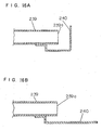
- FIG. 16A is a sectional view showing an area near the opening of a suction pipe at low outside-air temperature in embodiment 6 of the present invention.
- FIG. 16B is a sectional view showing the area near the opening of the suction pipe at high outside-air temperature in embodiment 6 of the present invention.
- components having the same functions and configurations as those of the hermetic-type compressor of each of the above-mentioned embodiments are designated by the same marks, and their descriptions are omitted.
- FIG. 17 is a vertical sectional view showing the hermetic-type compressor in accordance with embodiment 7 of the present invention.
- FIG. 18 is a plan sectional view showing the hermetic-type compressor of embodiment 7 of the present invention.
- components having the same functions and configurations as those of the hermetic-type compressor of each of the above-mentioned embodiments are designated by the same marks, and their descriptions are omitted.
- the enclosed container 2 comprises a lower shell 3 and an upper shell 4.
- Mark a in FIG. 18 represents the maximum distance in a direction perpendicular to the reciprocating direction of a piston 11 inside the enclosed container 2
- mark b represents the maximum distance in the reciprocating direction of the piston 11 inside the enclosed container 2.
- Mark c in FIG. 17 represents the maximum distance in the axial direction of a crankshaft 12 from the inner surface of the enclosed container 2 to the surface of lubricant 17.
- the refrigerant gas in the enclosed container 2 has natural resonance frequencies in the corresponding directions. In the hermetic-type compressor of embodiment 7, the distances a, b and c have been adjusted so that those resonance frequencies are not close to integral multiples of the rotation number of the crankshaft 12.
- the first suction pipe 230 communicates with the suction hole 19a, a pressure wave is generated, and an effect of raising suction pressure can be obtained. Therefore, the refrigeration capability of the hermetic-type compressor of embodiment 12 is raised.
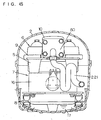
- the opening end 241a of the first suction pipe 241 in the space inside the enclosed container 2 is disposed on a plane passing through the center point of the line segment (v) indicated by distance a in FIG. 36 and perpendicular to the line segment (v).
- the plane has a node of the resonance mode generated in the direction perpendicular to the reciprocating direction on the horizontal plane including the reciprocating direction of the piston 11. Therefore, the pressure pulsation component for causing the resonance mode is positioned at the node of the resonance mode. Consequently, vibration occurs at the node of the resonance mode, whereby no resonance mode is caused, and the generation of resonance sound can be prevented.
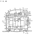
- FIG. 38 is a vertical sectional view showing the hermetic-type compressor in accordance with embodiment 14 of the present invention when the compressor has a node of a resonance mode in a direction perpendicular to the reciprocating direction on a horizontal plane including the reciprocating direction of the piston 11.
- FIG. 39 is a plan sectional view showing the hermetic-type compressor of embodiment 14 when the compressor has a node of a resonance mode in the direction perpendicular to the reciprocating direction on the horizontal plane including the reciprocating direction of its piston.
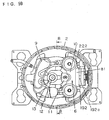
- the hermetic-type compressor of embodiment 15 by forming the first suction pipe used as a suction passage in the shape of a spiral suction pipe 212 as shown in FIGs. 42 and 43, the curvature of the bent portions 212b can be made larger. Therefore, in the hermetic-type compressor of embodiment 15, the attenuation of the pressure in the first suction pipe 212 can be reduced further.
- the temperature distribution of the first suction pipe 231 can be made uniform, and a change in the velocity of sound in the refrigerant gas can be decreased. Therefore, in the hermetic-type compressor of embodiment 17, the attenuation of the pressure wave can be decreased, and the suction pressure of the refrigerant gas can be raised stably, and the improvement effect of stable refrigeration capability can be obtained.
- the hermetic-type compressor of embodiment 19 by decreasing the temperature rise of refrigerant gas to be sucked, the density of the refrigerant gas is raised, and the circulation amount of refrigerant is increased, whereby efficiency can be raised.
- the broken lines (1) and (2) indicate cases when the hermetic-type compressors of embodiment 20 having different cylinder volumes were subjected to rotation number control.
- the single-dot chain line indicates a case when refrigeration capability increases in proportion to an increase in rotation number.
- the conventional hermetic-type compressor shown in FIG. 71 and described in the background art is described below.
- the pressure wave (expansion wave) generated during a suction stroke becomes a reflected wave Wb (compression wave) having an inverse phase in the space inside the enclosed container 2, and returns to the suction hole 19a.
- the opening/closing surface of the suction lead 20 has an angle nearly perpendicular to the propagation direction of the reflected wave Wb
- the reflected wave Wb is mostly reflected in the nearly opposite direction by the suction lead 20. Therefore, in the conventional hermetic-type compressor, the pressure energy of the reflected wave Wb does not work effectively in the cylinder 10, whereby a problem occurs, that is, the effect of supercharging cannot be obtained sufficiently.
- the improvement effect of refrigeration capability due to a supercharging effect can be obtained sufficiently at high outside-air temperature at which high refrigeration capability is required.
Landscapes
- Engineering & Computer Science (AREA)
- Mechanical Engineering (AREA)
- General Engineering & Computer Science (AREA)
- Compressor (AREA)
Claims (12)
- Compresseur hermétique comprenant:un moteur électrique (7),une portion mécanique (6) entraînée par ledit moteur électrique, et un conteneur fermé (2) pour accueillir ledit moteur électrique (7) et ladite portion mécanique (6);dans lequel ladite portion mécanique (6) comprend
un cylindre (10),
un piston (11) en mouvement de va et vient dans ledit cylindre (10), une plaque de soupapes (19, 150, 191, 194, 195, 211, 263) disposée à la surface d'extrémité dudit cylindre (10) et ayant un trou d'aspiration (19a, 150a, 191a, 192a, 194a, 195a, 211a, 273), et
un passage d'aspiration (22, 23, 24, 27, 29, 193, 200, 201, 212, 214, 215, 220, 221, 222, 229, 231, 239), dont une extrémité est substantiellement directement connectée audit trou d'aspiration (19a, 150a, 191a, 192a, 194a, 195a, 211a, 273), et dont l'autre extrémité est disposée dans l'espace à l'intérieur dudit conteneur fermé (2);
caractérisé en ce que
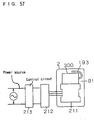
ledit moteur électrique (7) entraîné par un appareil inverseur (212) fonctionne à 2 ou davantage de signaux de fréquences différentes et au moins une partie dudit passage d'aspiration (22, 23, 24, 27, 29, 193, 200, 201, 212, 214, 215, 220, 221, 222, 229, 231, 239) est formée en polytétrafuoroéthylène (téflon) ou en téréphtalate de polybutylène (PBT) comme un matériau ayant une basse conductivité thermique. - Compresseur hermétique en conformité avec la revendication 1, dans lequel ladite portion mécanique (6) a un silencieux d'aspiration (28), et
une extrémité dudit passage d'aspiration (22, 23, 24, 27, 29, 193, 200, 201, 212, 214, 215, 220, 221, 222, 229, 231, 239) est substantiellement directement connectée audit trou d'aspiration (19a) de ladite plaque de soupapes (19), et l'autre extrémité duquel est disposée dans ledit silencieux (28) comme une extrémité d'ouverture. - Compresseur hermétique en conformité avec la revendication 1, dans lequel ladite portion mécanique (6) a un silencieux d'aspiration (28), et
ledit silencieux d'aspiration (28) est disposé de manière à couvrir substantiellement ledit passage d'aspiration (29). - Compresseur hermétique en conformité avec la revendication 1, comprenant en plus une tête d'aspiration (204, 293, 304, 325) pour ouvrir et fermer ledit trou d'aspiration (19a, 150a, 192a, 194a, 195a, 211a, 273) et un vilebrequin (12),
dans lequel, en supposant que l'angle de bielle au début d'ouverture de ladite tête d'aspiration est θs (radians), que la longueur dudit passage d'aspiration (22, 23, 24, 27, 29, 193, 200, 201, 212, 214, 215, 220, 221, 222, 229, 231, 239) est L (m), que le nombre de rotations dudit vilebrequin (12) est f (Hz), et que la vitesse du son dans le gaz réfrigérant dans ledit passage d'aspiration (22, 23, 24, 27, 29, 193, 200, 201, 212, 214, 215, 220, 221, 222, 229, 231, 239) est As (m/sec), l'angle de bielle de retour θr (radians) de l'onde de pression générée au niveau dudit trou d'aspiration (19a, 150a, 192a, 194a, 195a, 211a, 273) au début de l'aspiration, représenté par (équation 1) décrite ci-dessous, est dans la gamme de (équation 2) décrite ci-dessous.

- Compresseur hermétique en conformité avec la revendication 1, dans lequel la fréquence de résonance du gaz réfrigérant dans ledit conteneur fermé (2) est une fréquence différente d'une valeur proche d'une gamme de fréquences correspondant aux multiples intégraux du nombre de rotations d'un vilebrequin (12) entraîné par une portion de moteur électrique utilisée comme une source de puissance.
- Compresseur hermétique en conformité avec la revendication 1,
dans lequel ledit passage d'aspiration (22, 23, 24, 27, 29, 193, 200, 201, 212, 214, 215, 220, 221, 222, 229, 231, 239) a un premier tuyau d'aspiration,
dans lequel une extrémité dudit premier tuyau d'aspiration est substantiellement connectée audit trou d'aspiration, et
l'autre extrémité duquel est disposée dans l'espace à l'intérieur dudit conteneur fermé (2) comme une extrémité d'ouverture, et
un deuxième tuyau d'aspiration a une extrémité d'ouverture disposée à proximité de ladite extrémité d'ouverture dudit premier tuyau d'aspiration. - Compresseur hermétique en conformité avec la revendication 1, dans lequel une extrémité dudit passage d'aspiration (22, 23, 24, 27, 29, 193, 200, 201, 212, 214, 215, 220, 221, 222, 229, 231, 239) est substantiellement directement connectée audit trou d'aspiration (19a, 150a, 191a, 192a, 194a, 195a, 211a, 273), et les autres extrémités duquel sont disposées dans l'espace à l'intérieur dudit conteneur fermé (2) comme une multitude d'extrémités d'ouvertures, où les longueurs à partir dudit trou d'aspiration auxdites extrémités d'ouvertures multiples ont au moins deux types de valeurs.
- Compresseur hermétique en conformité avec la revendication 1,
dans lequel ledit passage d'aspiration (22, 23, 24, 27, 29, 193, 200, 201, 212, 214, 215, 220, 221, 222, 229, 231, 239) a des portions courbées ayan une courbure substantiellement uniforme. - Compresseur hermétique en conformité avec la revendication 1, dans lequel ledit passage d'aspiration (22, 23, 24, 27, 29, 193, 200, 201, 212, 214, 215, 220, 221, 222, 229, 231, 239) est courbé plusieurs fois et formé de sorte que des portions du passage d'aspiration soient proches les unes des autres.
- Compresseur hermétique en conformité avec la revendication 1, comprenant en plus une tête d'aspiration (20, 293, 304, 325) pour ouvrir et fermer ledit trou d'aspiration (19a, 150a, 192a, 194a, 195a, 211a, 273),
dans lequel ledit passage d'aspiration (200, 222) est pourvu d'un silencieux du type à résonance (232). - Compresseur hermétique en conformité avec la revendication 1,
comprenant en plus une tête d'aspiration (20, 293, 304, 325) pour ouvrir et fermer ledit trou d'aspiration (19a, 150a, 192a, 194a, 195a, 211a, 273),
dans lequel, au niveau de la portion de connexion directe entre ledit trou d'aspiration (19a, 150a, 192a, 194a, 195a, 211a, 273) et dudit passage d'aspiration (200, 210, 222, 230), la direction axiale dudit passage d'aspiration (22, 23, 24, 27, 29, 193, 200, 201, 212, 214, 215, 220, 221, 222, 229, 231, 239) a un angle inférieur à 90 degrés par rapport à la surface de connexion de ladite plaque de soupapes (19, 150, 191, 194, 195, 211, 263). - Compresseur hermétique en conformité avec la revendication 1,
comprenant en plus une tête d'aspiration (20, 293, 304, 325) pour ouvrir et fermer ledit trou d'aspiration (19a, 150a, 192a, 194a, 195a, 211 a, 273), et
un mécanisme de commande de déviation (314) pour commander la grandeur de déviation initiale de ladite tête d'aspiration.
Applications Claiming Priority (15)
| Application Number | Priority Date | Filing Date | Title |
|---|---|---|---|
| JP15397396 | 1996-06-14 | ||
| JP15397396 | 1996-06-14 | ||
| JP28637696 | 1996-10-29 | ||
| JP28637696 | 1996-10-29 | ||
| JP29612396 | 1996-11-08 | ||
| JP29612396 | 1996-11-08 | ||
| JP2492597 | 1997-02-07 | ||
| JP2492597 | 1997-02-07 | ||
| JP2648897 | 1997-02-10 | ||
| JP2648897 | 1997-02-10 | ||
| JP9348397 | 1997-04-11 | ||
| JP9348397 | 1997-04-11 | ||
| JP12823197 | 1997-05-19 | ||
| JP12823197 | 1997-05-19 | ||
| EP97926251A EP0845595B1 (fr) | 1996-06-14 | 1997-06-12 | Compresseur hermetique |
Related Parent Applications (2)
| Application Number | Title | Priority Date | Filing Date |
|---|---|---|---|
| EP97926251A Division EP0845595B1 (fr) | 1996-06-14 | 1997-06-12 | Compresseur hermetique |
| EP97926251.6 Division | 1997-12-18 |
Publications (2)
| Publication Number | Publication Date |
|---|---|
| EP1538334A1 EP1538334A1 (fr) | 2005-06-08 |
| EP1538334B1 true EP1538334B1 (fr) | 2007-08-15 |
Family
ID=27564046
Family Applications (2)
| Application Number | Title | Priority Date | Filing Date |
|---|---|---|---|
| EP97926251A Expired - Lifetime EP0845595B1 (fr) | 1996-06-14 | 1997-06-12 | Compresseur hermetique |
| EP05003059A Expired - Lifetime EP1538334B1 (fr) | 1996-06-14 | 1997-06-12 | Compresseur hermétique |
Family Applications Before (1)
| Application Number | Title | Priority Date | Filing Date |
|---|---|---|---|
| EP97926251A Expired - Lifetime EP0845595B1 (fr) | 1996-06-14 | 1997-06-12 | Compresseur hermetique |
Country Status (8)
| Country | Link |
|---|---|
| US (1) | US6152703A (fr) |
| EP (2) | EP0845595B1 (fr) |
| JP (1) | JP4055828B2 (fr) |
| KR (1) | KR100277283B1 (fr) |
| CN (2) | CN1519473A (fr) |
| BR (1) | BR9702316A (fr) |
| DE (2) | DE69733402T2 (fr) |
| WO (1) | WO1997047882A1 (fr) |
Families Citing this family (25)
| Publication number | Priority date | Publication date | Assignee | Title |
|---|---|---|---|---|
| BR0117028B1 (pt) * | 2001-05-25 | 2012-02-07 | válvula de sucção para compressor com movimento de vaivém. | |
| KR100504445B1 (ko) * | 2003-03-05 | 2005-08-01 | 삼성광주전자 주식회사 | 압축기용 실린더 조립체, 압축기 및 압축기가 적용된냉매순환회로를 가지는 장치 |
| JP2004360686A (ja) * | 2003-05-12 | 2004-12-24 | Matsushita Electric Ind Co Ltd | 冷媒圧縮機 |
| US6935848B2 (en) * | 2003-05-19 | 2005-08-30 | Bristol Compressors, Inc. | Discharge muffler placement in a compressor |
| US20040234386A1 (en) * | 2003-05-19 | 2004-11-25 | Chumley Eugene Karl | Discharge muffler having an internal pressure relief valve |
| WO2005033510A1 (fr) * | 2003-09-30 | 2005-04-14 | Calsonic Kansei Corporation | Compresseur et structure a soupape d'aspiration |
| JP2005133707A (ja) * | 2003-10-10 | 2005-05-26 | Matsushita Electric Ind Co Ltd | 密閉型圧縮機 |
| KR100564439B1 (ko) * | 2003-11-14 | 2006-03-29 | 엘지전자 주식회사 | 밀폐형압축기 |
| JP4429769B2 (ja) * | 2004-03-16 | 2010-03-10 | パナソニック株式会社 | 密閉型圧縮機 |
| JP4576944B2 (ja) * | 2004-09-13 | 2010-11-10 | パナソニック株式会社 | 冷媒圧縮機 |
| EP1715189B1 (fr) * | 2005-04-22 | 2013-12-04 | Kaeser Kompressoren AG | Silencieux développé pour et destiné à un compresseur |
| TR200800419T1 (tr) * | 2005-08-05 | 2008-07-21 | Arçeli̇k Anoni̇m Şi̇rketi̇ | Bir kompresör |
| KR20080045558A (ko) * | 2006-11-20 | 2008-05-23 | 삼성광주전자 주식회사 | 밀폐형 압축기 |
| US20080253900A1 (en) * | 2007-04-11 | 2008-10-16 | Harris Ralph E | Gas compressor with pulsation absorber for reducing cylinder nozzle resonant pulsation |
| US8123498B2 (en) | 2008-01-24 | 2012-02-28 | Southern Gas Association Gas Machinery Research Council | Tunable choke tube for pulsation control device used with gas compressor |
| KR101457703B1 (ko) * | 2008-10-28 | 2014-11-04 | 엘지전자 주식회사 | 압축기 |
| US8591208B2 (en) * | 2009-06-24 | 2013-11-26 | Southwest Research Institute | Multi-frequency pulsation absorber at cylinder valve cap |
| EP2780596A1 (fr) * | 2011-10-03 | 2014-09-24 | Arçelik Anonim Sirketi | Compresseur comprenant un élément de protection |
| ITCO20110070A1 (it) * | 2011-12-20 | 2013-06-21 | Nuovo Pignone Spa | Metodi e dispositivi per usare costruttivamente le pulsazioni di pressione in installazioni di compressori alternativi |
| BR102014007254A2 (pt) * | 2014-03-26 | 2015-12-08 | Whirlpool Sa | dispositivo seletor de fluidos para compressor alternativo e filtro acústico provido de dispositivo seletor de fluidos |
| CN105332889A (zh) * | 2015-10-26 | 2016-02-17 | 无锡市圣科不锈钢气动自控阀门厂 | 一种往复式压缩机 |
| CZ31461U1 (cs) * | 2017-11-14 | 2018-02-13 | Industrial Technology s.r.o. | Zařízení pro eliminaci šíření hluku |
| CN110671307B (zh) * | 2019-10-15 | 2025-08-12 | 珠海凌达压缩机有限公司 | 压缩机保护装置、压缩机及空调器 |
| CN112878965A (zh) * | 2021-03-29 | 2021-06-01 | 吉林石油装备技术工程服务有限公司 | 一种游梁以及抽油机 |
| CN116163920A (zh) * | 2022-02-18 | 2023-05-26 | 安徽美芝制冷设备有限公司 | 压缩气缸、压缩机及制冷设备 |
Family Cites Families (47)
| Publication number | Priority date | Publication date | Assignee | Title |
|---|---|---|---|---|
| DE976269C (de) * | 1942-04-03 | 1963-06-06 | Kloeckner Humboldt Deutz Ag | Verdichter, insbesondere zum Spuelen oder Aufladen von Brennkraftmaschinen |
| GB627074A (en) * | 1946-01-26 | 1949-07-27 | Fluor Corp | Improvements in or relating to manifold devices for dampening pressure pulsations ingaseous currents |
| CH354540A (fr) * | 1958-02-14 | 1961-05-31 | Chausson Usines Sa | Dispositif d'insonorisation d'un compresseur à organe moteur oscillant à commande électromagnétique |
| GB880192A (en) * | 1960-02-11 | 1961-10-18 | Wilhelm Sydow Everett | Fluid surge alleviator |
| GB1320324A (en) * | 1969-09-05 | 1973-06-13 | Edwards High Vacuum Int Ltd | Silencers for vacuum pumps |
| JPS5123925Y2 (fr) * | 1971-04-15 | 1976-06-19 | ||
| GB1412404A (en) * | 1971-09-10 | 1975-11-05 | Quietflo Eng Ltd | Silencing devices for compressors |
| US3864064A (en) * | 1973-03-12 | 1975-02-04 | Sundstrand Corp | Suction muffler tube for compressor |
| JPS53130509A (en) * | 1977-04-20 | 1978-11-14 | Hitachi Ltd | Totally-enclosed motor compressor |
| US4239461A (en) * | 1978-11-06 | 1980-12-16 | Copeland Corporation | Compressor induction system |
| JPS55165978U (fr) * | 1979-05-16 | 1980-11-28 | ||
| DE2951463A1 (de) * | 1979-12-20 | 1981-07-02 | Copeland Corp., Sidney, Ohio | Kompressoransaugsystem |
| JPS606629Y2 (ja) * | 1980-05-16 | 1985-03-02 | 三洋電機株式会社 | 密閉型圧縮機 |
| JPS57122192A (en) | 1981-01-20 | 1982-07-29 | Mitsubishi Electric Corp | Rotary compressor |
| US4401418B1 (en) * | 1981-04-29 | 1998-01-06 | White Consolidated Ind Inc | Muffler system for refrigeration compressor |
| US4477229A (en) * | 1982-08-25 | 1984-10-16 | Carrier Corporation | Compressor assembly and method of attaching a suction muffler thereto |
| JPS6026290U (ja) * | 1983-07-29 | 1985-02-22 | 株式会社東芝 | 密閉型圧縮機 |
| JPS60125790A (ja) * | 1983-12-13 | 1985-07-05 | Sanyo Electric Co Ltd | 電動圧縮機の防振装置 |
| US4549857A (en) * | 1984-08-03 | 1985-10-29 | Carrier Corporation | Hermetic motor compressor having a suction inlet and seal |
| JPS61132782A (ja) * | 1984-11-29 | 1986-06-20 | Toshiba Corp | 圧縮機のバルブカバ−の製造方法 |
| JPS61178581A (ja) * | 1985-02-05 | 1986-08-11 | Matsushita Refrig Co | 往復型圧縮機 |
| JPS6245388U (fr) * | 1985-09-10 | 1987-03-19 | ||
| JPH0415993Y2 (fr) * | 1985-12-18 | 1992-04-09 | ||
| US4856286A (en) * | 1987-12-02 | 1989-08-15 | American Standard Inc. | Refrigeration compressor driven by a DC motor |
| DD266402A1 (de) * | 1987-12-11 | 1989-03-29 | Dkk Scharfenstein Veb | Zylindertraeger fuer hermetische kaeltemittelverdichter |
| JPH03175177A (ja) * | 1989-12-05 | 1991-07-30 | Matsushita Refrig Co Ltd | 密閉型電動圧縮機 |
| US4988269A (en) * | 1990-02-08 | 1991-01-29 | Copeland Corporation | Compressor discharge gas sound attenuation |
| US5203178A (en) * | 1990-10-30 | 1993-04-20 | Norm Pacific Automation Corp. | Noise control of air conditioner |
| JPH04191476A (ja) * | 1990-11-22 | 1992-07-09 | Matsushita Refrig Co Ltd | 密閉型電動圧縮機 |
| US5288212A (en) * | 1990-12-12 | 1994-02-22 | Goldstar Co., Ltd. | Cylinder head of hermetic reciprocating compressor |
| EP0505805B1 (fr) * | 1991-03-28 | 1995-03-08 | Tecumseh Products Company | Système d'aspiration intégré |
| BR9102288A (pt) * | 1991-05-28 | 1993-01-05 | Brasileira S A Embraco Empresa | Conjunto abafador de succao para compressor hermetico |
| DE9203857U1 (de) * | 1992-03-23 | 1992-05-14 | ABB Patent GmbH, 6800 Mannheim | Kälteanlage |
| US5183974A (en) * | 1992-04-03 | 1993-02-02 | General Motors Corporation | Gas pulsation attenuator for automotive air conditioning compressor |
| JP3040250B2 (ja) * | 1992-04-06 | 2000-05-15 | 松下冷機株式会社 | 密閉型圧縮機 |
| JPH0650262A (ja) | 1992-07-31 | 1994-02-22 | Matsushita Refrig Co Ltd | 往復型圧縮機 |
| JPH0674154A (ja) * | 1992-08-26 | 1994-03-15 | Matsushita Refrig Co Ltd | 密閉型圧縮機 |
| US5328338A (en) * | 1993-03-01 | 1994-07-12 | Sanyo Electric Co., Ltd. | Hermetically sealed electric motor compressor |
| KR200141490Y1 (ko) * | 1993-04-24 | 1999-05-15 | 김광호 | 압축기의소음감쇠장치 |
| WO1994028305A1 (fr) * | 1993-05-21 | 1994-12-08 | Kabushiki Kaisha Toyoda Jidoshokki Seisakusho | Compresseur a piston |
| DE4321013C5 (de) * | 1993-06-24 | 2014-07-17 | Wabco Gmbh | Gasverdichter |
| JPH0763167A (ja) * | 1993-08-20 | 1995-03-07 | Tokico Ltd | 多段式圧縮機 |
| JPH07208334A (ja) * | 1994-01-24 | 1995-08-08 | Matsushita Refrig Co Ltd | 密閉型圧縮機 |
| JPH07293468A (ja) * | 1994-04-28 | 1995-11-07 | Toshiba Corp | 密閉形コンプレッサ |
| KR0143182B1 (ko) * | 1994-04-29 | 1998-08-01 | 김광호 | 압축기 |
| GB9410609D0 (en) * | 1994-05-26 | 1994-07-13 | Secr Defence | Acoustic enclosure |
| US5496156A (en) * | 1994-09-22 | 1996-03-05 | Tecumseh Products Company | Suction muffler |
-
1997
- 1997-06-12 CN CNA2004100033158A patent/CN1519473A/zh active Pending
- 1997-06-12 CN CNB971907161A patent/CN1163668C/zh not_active Expired - Fee Related
- 1997-06-12 DE DE69733402T patent/DE69733402T2/de not_active Expired - Fee Related
- 1997-06-12 US US09/011,672 patent/US6152703A/en not_active Expired - Lifetime
- 1997-06-12 JP JP53875297A patent/JP4055828B2/ja not_active Expired - Fee Related
- 1997-06-12 KR KR1019980701059A patent/KR100277283B1/ko not_active Expired - Fee Related
- 1997-06-12 EP EP97926251A patent/EP0845595B1/fr not_active Expired - Lifetime
- 1997-06-12 WO PCT/JP1997/002058 patent/WO1997047882A1/fr not_active Ceased
- 1997-06-12 EP EP05003059A patent/EP1538334B1/fr not_active Expired - Lifetime
- 1997-06-12 BR BR9702316A patent/BR9702316A/pt not_active IP Right Cessation
- 1997-06-12 DE DE69738038T patent/DE69738038T2/de not_active Expired - Fee Related
Also Published As
| Publication number | Publication date |
|---|---|
| DE69733402D1 (de) | 2005-07-07 |
| EP0845595A1 (fr) | 1998-06-03 |
| DE69738038T2 (de) | 2008-04-30 |
| KR100277283B1 (ko) | 2001-01-15 |
| KR19990036390A (ko) | 1999-05-25 |
| EP0845595B1 (fr) | 2005-06-01 |
| DE69733402T2 (de) | 2006-04-27 |
| JP4055828B2 (ja) | 2008-03-05 |
| WO1997047882A1 (fr) | 1997-12-18 |
| DE69738038D1 (de) | 2007-09-27 |
| US6152703A (en) | 2000-11-28 |
| EP1538334A1 (fr) | 2005-06-08 |
| CN1519473A (zh) | 2004-08-11 |
| CN1195392A (zh) | 1998-10-07 |
| CN1163668C (zh) | 2004-08-25 |
| BR9702316A (pt) | 1999-03-09 |
| EP0845595A4 (fr) | 2001-03-21 |
Similar Documents
| Publication | Publication Date | Title |
|---|---|---|
| EP1538334B1 (fr) | Compresseur hermétique | |
| US5288212A (en) | Cylinder head of hermetic reciprocating compressor | |
| CA2069208C (fr) | Compresseur frigorifique muni d'un piston profile | |
| EP0588381B1 (fr) | Compresseur hermétique | |
| JPWO1997047882A1 (ja) | 密閉型圧縮機 | |
| KR100538855B1 (ko) | 밀폐형 전동 압축기 | |
| US20060039803A1 (en) | Hermetic compressor | |
| US20080003115A1 (en) | Hermetic type compressor | |
| EP3364030A1 (fr) | Compresseur ayant un boîtier | |
| JP3652361B2 (ja) | 密閉型電動圧縮機 | |
| US20040013552A1 (en) | Valve assembly in hermetic compressor | |
| JP2848418B2 (ja) | 密閉型電動圧縮機 | |
| JP2004138074A (ja) | 密閉型電動圧縮機 | |
| JP2000274363A (ja) | 密閉型圧縮機 | |
| JP2004092661A (ja) | 密閉型電動圧縮機 | |
| KR0184099B1 (ko) | 밀폐형 압축기의 토출소음기 | |
| KR100341420B1 (ko) | 저소음형 실린더 | |
| KR0132985Y1 (ko) | 압축기 | |
| JP2000087854A (ja) | 密閉型圧縮機 | |
| KR19980037760A (ko) | 압축기의 프랩퍼헝 밸브구조 | |
| JPH04124477A (ja) | 密閉型圧縮機 | |
| JPH11107916A (ja) | 密閉型圧縮機 | |
| MXPA97005152A (en) | Compre valve assembly | |
| JP2009079516A (ja) | 密閉型圧縮機 | |
| KR19980076773A (ko) | 왕복동 압축기의 플랩퍼형 밸브조립체의 카버 |
Legal Events
| Date | Code | Title | Description |
|---|---|---|---|
| PUAI | Public reference made under article 153(3) epc to a published international application that has entered the european phase |
Free format text: ORIGINAL CODE: 0009012 |
|
| 17P | Request for examination filed |
Effective date: 20050214 |
|
| AC | Divisional application: reference to earlier application |
Ref document number: 0845595 Country of ref document: EP Kind code of ref document: P |
|
| AK | Designated contracting states |
Kind code of ref document: A1 Designated state(s): DE FR GB IT |
|
| RIN1 | Information on inventor provided before grant (corrected) |
Inventor name: YAGI, AKIO Inventor name: AKASHI, HIRONARI Inventor name: YOSHIMURA, TAKAO Inventor name: HAYASHI, AKIRA,KOSMO SHONAN B202 |
|
| AKX | Designation fees paid |
Designated state(s): DE FR GB IT |
|
| 17Q | First examination report despatched |
Effective date: 20050921 |
|
| GRAP | Despatch of communication of intention to grant a patent |
Free format text: ORIGINAL CODE: EPIDOSNIGR1 |
|
| RIN1 | Information on inventor provided before grant (corrected) |
Inventor name: YAGI, AKIO Inventor name: YOSHIMURA, TAKAO Inventor name: AKASHI, HIRONARI Inventor name: INOUE AKIRA,KOSMO SHONAN B202 |
|
| GRAS | Grant fee paid |
Free format text: ORIGINAL CODE: EPIDOSNIGR3 |
|
| GRAA | (expected) grant |
Free format text: ORIGINAL CODE: 0009210 |
|
| AC | Divisional application: reference to earlier application |
Ref document number: 0845595 Country of ref document: EP Kind code of ref document: P |
|
| AK | Designated contracting states |
Kind code of ref document: B1 Designated state(s): DE FR GB IT |
|
| REG | Reference to a national code |
Ref country code: GB Ref legal event code: FG4D |
|
| REF | Corresponds to: |
Ref document number: 69738038 Country of ref document: DE Date of ref document: 20070927 Kind code of ref document: P |
|
| EN | Fr: translation not filed | ||
| PLBE | No opposition filed within time limit |
Free format text: ORIGINAL CODE: 0009261 |
|
| STAA | Information on the status of an ep patent application or granted ep patent |
Free format text: STATUS: NO OPPOSITION FILED WITHIN TIME LIMIT |
|
| 26N | No opposition filed |
Effective date: 20080516 |
|
| GBPC | Gb: european patent ceased through non-payment of renewal fee |
Effective date: 20080612 |
|
| PG25 | Lapsed in a contracting state [announced via postgrant information from national office to epo] |
Ref country code: GB Free format text: LAPSE BECAUSE OF NON-PAYMENT OF DUE FEES Effective date: 20080612 |
|
| PGFP | Annual fee paid to national office [announced via postgrant information from national office to epo] |
Ref country code: IT Payment date: 20090620 Year of fee payment: 13 |
|
| PGFP | Annual fee paid to national office [announced via postgrant information from national office to epo] |
Ref country code: DE Payment date: 20090604 Year of fee payment: 13 |
|
| PG25 | Lapsed in a contracting state [announced via postgrant information from national office to epo] |
Ref country code: IT Free format text: LAPSE BECAUSE OF NON-PAYMENT OF DUE FEES Effective date: 20100612 |
|
| PG25 | Lapsed in a contracting state [announced via postgrant information from national office to epo] |
Ref country code: DE Free format text: LAPSE BECAUSE OF NON-PAYMENT OF DUE FEES Effective date: 20110101 |
|
| PG25 | Lapsed in a contracting state [announced via postgrant information from national office to epo] |
Ref country code: FR Free format text: LAPSE BECAUSE OF FAILURE TO SUBMIT A TRANSLATION OF THE DESCRIPTION OR TO PAY THE FEE WITHIN THE PRESCRIBED TIME-LIMIT Effective date: 20080411 |