EP1538438B1 - Systeme et procede d'identification de type d'essence - Google Patents
Systeme et procede d'identification de type d'essence Download PDFInfo
- Publication number
- EP1538438B1 EP1538438B1 EP03795369.2A EP03795369A EP1538438B1 EP 1538438 B1 EP1538438 B1 EP 1538438B1 EP 03795369 A EP03795369 A EP 03795369A EP 1538438 B1 EP1538438 B1 EP 1538438B1
- Authority
- EP
- European Patent Office
- Prior art keywords
- gasoline
- identifying
- liquid type
- liquid
- type
- Prior art date
- Legal status (The legal status is an assumption and is not a legal conclusion. Google has not performed a legal analysis and makes no representation as to the accuracy of the status listed.)
- Expired - Lifetime
Links
Images






Classifications
-
- F—MECHANICAL ENGINEERING; LIGHTING; HEATING; WEAPONS; BLASTING
- F02—COMBUSTION ENGINES; HOT-GAS OR COMBUSTION-PRODUCT ENGINE PLANTS
- F02D—CONTROLLING COMBUSTION ENGINES
- F02D41/00—Electrical control of supply of combustible mixture or its constituents
- F02D41/0025—Controlling engines characterised by use of non-liquid fuels, pluralities of fuels, or non-fuel substances added to the combustible mixtures
-
- F—MECHANICAL ENGINEERING; LIGHTING; HEATING; WEAPONS; BLASTING
- F02—COMBUSTION ENGINES; HOT-GAS OR COMBUSTION-PRODUCT ENGINE PLANTS
- F02D—CONTROLLING COMBUSTION ENGINES
- F02D19/00—Controlling engines characterised by their use of non-liquid fuels, pluralities of fuels, or non-fuel substances added to the combustible mixtures
- F02D19/06—Controlling engines characterised by their use of non-liquid fuels, pluralities of fuels, or non-fuel substances added to the combustible mixtures peculiar to engines working with pluralities of fuels, e.g. alternatively with light and heavy fuel oil, other than engines indifferent to the fuel consumed
- F02D19/0626—Measuring or estimating parameters related to the fuel supply system
- F02D19/0634—Determining a density, viscosity, composition or concentration
-
- F—MECHANICAL ENGINEERING; LIGHTING; HEATING; WEAPONS; BLASTING
- F02—COMBUSTION ENGINES; HOT-GAS OR COMBUSTION-PRODUCT ENGINE PLANTS
- F02D—CONTROLLING COMBUSTION ENGINES
- F02D19/00—Controlling engines characterised by their use of non-liquid fuels, pluralities of fuels, or non-fuel substances added to the combustible mixtures
- F02D19/06—Controlling engines characterised by their use of non-liquid fuels, pluralities of fuels, or non-fuel substances added to the combustible mixtures peculiar to engines working with pluralities of fuels, e.g. alternatively with light and heavy fuel oil, other than engines indifferent to the fuel consumed
- F02D19/08—Controlling engines characterised by their use of non-liquid fuels, pluralities of fuels, or non-fuel substances added to the combustible mixtures peculiar to engines working with pluralities of fuels, e.g. alternatively with light and heavy fuel oil, other than engines indifferent to the fuel consumed simultaneously using pluralities of fuels
- F02D19/082—Premixed fuels, i.e. emulsions or blends
- F02D19/084—Blends of gasoline and alcohols, e.g. E85
-
- F—MECHANICAL ENGINEERING; LIGHTING; HEATING; WEAPONS; BLASTING
- F02—COMBUSTION ENGINES; HOT-GAS OR COMBUSTION-PRODUCT ENGINE PLANTS
- F02M—SUPPLYING COMBUSTION ENGINES IN GENERAL WITH COMBUSTIBLE MIXTURES OR CONSTITUENTS THEREOF
- F02M7/00—Carburettors with means for influencing, e.g. enriching or keeping constant, fuel/air ratio of charge under varying conditions
-
- G—PHYSICS
- G01—MEASURING; TESTING
- G01N—INVESTIGATING OR ANALYSING MATERIALS BY DETERMINING THEIR CHEMICAL OR PHYSICAL PROPERTIES
- G01N27/00—Investigating or analysing materials by the use of electric, electrochemical, or magnetic means
- G01N27/02—Investigating or analysing materials by the use of electric, electrochemical, or magnetic means by investigating impedance
- G01N27/04—Investigating or analysing materials by the use of electric, electrochemical, or magnetic means by investigating impedance by investigating resistance
- G01N27/14—Investigating or analysing materials by the use of electric, electrochemical, or magnetic means by investigating impedance by investigating resistance of an electrically-heated body in dependence upon change of temperature
- G01N27/18—Investigating or analysing materials by the use of electric, electrochemical, or magnetic means by investigating impedance by investigating resistance of an electrically-heated body in dependence upon change of temperature caused by changes in the thermal conductivity of a surrounding material to be tested
-
- G—PHYSICS
- G01—MEASURING; TESTING
- G01N—INVESTIGATING OR ANALYSING MATERIALS BY DETERMINING THEIR CHEMICAL OR PHYSICAL PROPERTIES
- G01N33/00—Investigating or analysing materials by specific methods not covered by groups G01N1/00 - G01N31/00
- G01N33/26—Oils; Viscous liquids; Paints; Inks
- G01N33/28—Oils, i.e. hydrocarbon liquids
- G01N33/2829—Mixtures of fuels
-
- F—MECHANICAL ENGINEERING; LIGHTING; HEATING; WEAPONS; BLASTING
- F02—COMBUSTION ENGINES; HOT-GAS OR COMBUSTION-PRODUCT ENGINE PLANTS
- F02D—CONTROLLING COMBUSTION ENGINES
- F02D19/00—Controlling engines characterised by their use of non-liquid fuels, pluralities of fuels, or non-fuel substances added to the combustible mixtures
- F02D19/06—Controlling engines characterised by their use of non-liquid fuels, pluralities of fuels, or non-fuel substances added to the combustible mixtures peculiar to engines working with pluralities of fuels, e.g. alternatively with light and heavy fuel oil, other than engines indifferent to the fuel consumed
- F02D19/0663—Details on the fuel supply system, e.g. tanks, valves, pipes, pumps, rails, injectors or mixers
- F02D19/0665—Tanks, e.g. multiple tanks
-
- F—MECHANICAL ENGINEERING; LIGHTING; HEATING; WEAPONS; BLASTING
- F02—COMBUSTION ENGINES; HOT-GAS OR COMBUSTION-PRODUCT ENGINE PLANTS
- F02D—CONTROLLING COMBUSTION ENGINES
- F02D2200/00—Input parameters for engine control
- F02D2200/02—Input parameters for engine control the parameters being related to the engine
- F02D2200/06—Fuel or fuel supply system parameters
- F02D2200/0606—Fuel temperature
-
- F—MECHANICAL ENGINEERING; LIGHTING; HEATING; WEAPONS; BLASTING
- F02—COMBUSTION ENGINES; HOT-GAS OR COMBUSTION-PRODUCT ENGINE PLANTS
- F02D—CONTROLLING COMBUSTION ENGINES
- F02D2200/00—Input parameters for engine control
- F02D2200/02—Input parameters for engine control the parameters being related to the engine
- F02D2200/06—Fuel or fuel supply system parameters
- F02D2200/0611—Fuel type, fuel composition or fuel quality
-
- Y—GENERAL TAGGING OF NEW TECHNOLOGICAL DEVELOPMENTS; GENERAL TAGGING OF CROSS-SECTIONAL TECHNOLOGIES SPANNING OVER SEVERAL SECTIONS OF THE IPC; TECHNICAL SUBJECTS COVERED BY FORMER USPC CROSS-REFERENCE ART COLLECTIONS [XRACs] AND DIGESTS
- Y02—TECHNOLOGIES OR APPLICATIONS FOR MITIGATION OR ADAPTATION AGAINST CLIMATE CHANGE
- Y02T—CLIMATE CHANGE MITIGATION TECHNOLOGIES RELATED TO TRANSPORTATION
- Y02T10/00—Road transport of goods or passengers
- Y02T10/10—Internal combustion engine [ICE] based vehicles
- Y02T10/30—Use of alternative fuels, e.g. biofuels
Definitions
- the present invention relates to an apparatus and method for identifying the liquid type of a gasoline.
- the exhaust gas of a car contains pollutants such as unburned hydrocarbon (HC), an NOx gas and an SOx gas.
- pollutants such as unburned hydrocarbon (HC), an NOx gas and an SOx gas.
- S in a gasoline is removed for the SOx or unburned HC is burned by a catalyst, for example.
- a car system 100 takes air in through an automatic element (filter) 102 and feeds the air into an engine 106 through an air flow sensor 104. Moreover, the car system 100 feeds a gasoline in a gasoline tank 108 into the engine 106 through a gasoline pump 110.
- filter automatic element
- the injection of the fuel in the engine 106 is controlled by a fuel injection control device 114 in order to have a predetermined theoretical air fuel ratio.
- hydrocarbon (HC) in the exhaust gas is burned by a catalytic device 116 and is then discharged as the exhaust gas through an oxygen concentration sensor 118.
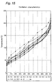
- gasolines sold all over the world include various gasolines having different distillation characteristics (different easinesses of evaporation) as shown in Fig. 15 .
- Fig. 15 shows the distillation characteristics of gasolines, illustrating a relationship between a percentage and a temperature. Namely, for example, an axis of abscissa of 50% (T50) indicates a temperature at which 50% of each gasoline evaporates.
- a gasoline A2 represents the heaviest gasoline (which rarely evaporates) and a gasoline No. 7 represents the lightest gasoline (which easily evaporates) with respect to a standard gasoline No. 3.
- the present inventors have proposed a fluid identifying method for causing a heating member to generate heat by carrying electricity, heating a temperature detector through the heat generation, thermally influencing a heat transfer from the heating member to the temperature detector through a fluid to be identified, and distinguishing the type of the identified fluid based on an electrical output corresponding to the electric resistance of the temperature detector, thereby periodically carrying the electricity to the heating member in Japanese Laid-Open Patent Publication No. 11(1999)-153561 (particularly see paragraphs [0042] to [0049]).
- the fluid identifying method it is necessary to periodically carry the electricity to the heating member (in a multipulse). For this reason, a long time is required for the identification so that it is hard to identify a fluid instantaneously.
- this method moreover, it is possible to identify a fluid based on a central value for substances having very different characteristics such as water, air and oil. However, it is hard to identify the gasolines having very close characteristics to each other accurately and rapidly.
- US 5535615 discloses a further example of a gas sensor suitable for detecting the fuel vapor content of a fuel-air mixture.
- the present invention has been made to solve the problems and to attain the objects in the prior art described above, and provides an apparatus for identifying a liquid type of a gasoline, comprising:
- the present invention provides a method for identifying a liquid type of a gasoline, comprising the steps of:
- the present invention provides the apparatus for identifying a liquid type of a gasoline, wherein the identification control portion identifies a type of a gasoline with the voltage output difference V0 obtained for the identified gasoline, which is based on calibration curve data to be a correlation of a voltage output difference with a temperature for a predetermined reference gasoline prestored in the identification control portion.
- the present invention provides the method for identifying a liquid type of a gasoline, wherein a type of a gasoline is identified with the voltage output difference V0 obtained for the identified gasoline, based on calibration curve data to be a correlation of a voltage output difference with a temperature for a predetermined reference gasoline which is prestored.
- the type of a gasoline is identified with the voltage output difference V0 obtained for the identified gasoline based on the calibration curve data to be the correlation of the voltage output difference with the temperature for the predetermined reference gasoline which is prestored. Therefore, it is possible to identify the type of the gasoline more accurately and rapidly.
- the present invention provides the apparatus for identifying a liquid type of a gasoline, wherein the identification control portion correlates a liquid type voltage output Vout for the voltage output difference V0 at a measuring temperature of the identified gasoline with an output voltage for a voltage output difference at a measuring temperature for a predetermined threshold reference gasoline and thus carries out a correction.
- the present invention provides the method for identifying a liquid type of a gasoline, wherein a liquid type voltage output Vout for the voltage output difference V0 at a measuring temperature of the identified gasoline is correlated with an output voltage for a voltage output difference at a measuring temperature for a predetermined threshold reference gasoline and is thus corrected.
- the liquid type voltage output Vout for the voltage output difference V0 at the measuring temperature of the identified gasoline is correlated with the output voltage for the voltage output difference at the measuring temperature for the predetermined threshold reference gasoline and is thus corrected. Consequently, it is possible to eliminate the influence of the temperature on the voltage output difference V0, thereby giving the correlation of the liquid type voltage output Vout with the characteristics of the gasoline more accurately. Thus, it is possible to identify the type of the gasoline further accurately and rapidly.
- the present invention is characterized in that the liquid type identifying sensor heater is a laminated liquid type identifying sensor heater inwhich a heater and an identifying liquid temperature sensor are laminated through an insulating layer.
- the senor portion can be constituted to be very small-sized. Consequently, it is possible to identify the liquid type of the gasoline accurately with a very excellent thermal responsiveness.
- the present invention is characterized in that the heater and the identifying liquid temperature sensor in the liquid type identifying sensor heater are constituted to come in contact with the identified gasoline through a metallic fin, respectively.
- the heater and the identifying liquid temperature sensor in the liquid type identifying sensor heater do not directly come in contact with the identified gasoline. Therefore, an operation failure is not caused by a deterioration with the passage of time, foreign matters in the gasoline or the like. Thus, it is possible to identify the liquid type of the gasoline accurately and rapidly.
- the present invention is characterized in that the liquid temperature sensor is constituted to come in contact with the identified gasoline through the metallic fin.
- the liquid temperature sensor does not directly come in contact with the identified gasoline. Therefore, an operation failure is not caused by a deterioration with the passage of time, foreign matters in the gasoline or the like. Thus, it is possible to identify the liquid type of the gasoline accurately and rapidly.
- the present invention provides an apparatus for identifying a liquid type of a gasoline of a car, comprising:
- the present invention provides a method for identifying a liquid type of a gasoline of a car, comprising the step of:
- the present invention provides an apparatus for reducing an exhaust gas of a car, comprising:
- the present invention provides a method for reducing an exhaust gas of a car, comprising the steps of:
- an ignition timing can be regulated based on the result of the identification of the type of the gasoline. Therefore, it is possible to obtain a proper ignition timing corresponding to the type of the gasoline.
- the present invention provides an apparatus for reducing an exhaust gas of a car, comprising:
- a gasoline compression control device for regulating a compressibility of the gasoline based on a type of the gasoline which is identified by the apparatus for identifying a liquid type of a gasoline.
- the present invention provides a method for reducing an exhaust gas of a car, comprising the steps of:
- the compressibility of the gasoline can be regulated based on the result of the identification of the type of the gasoline. Therefore, it is possible to obtain a proper compressibility of the gasoline corresponding to the type of the gasoline.
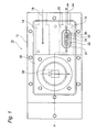
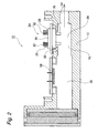
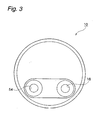
- an apparatus 10 for identifying the liquid type of a gasoline comprises a liquid type identifying apparatus body 12, and a first passage 14 and a second passage 16 which are formed in the liquid type identifying apparatus body 12.
- a gasoline to be identified which flows from a gasoline inlet 18 into the first passage 14 passes through an alcoholic contents detecting chamber 56. Then, the identified gasoline passes through the alcoholic contents detecting chamber 56, and thereafter, enters the second passage 16 to temporarily stay in a gasoline liquid type identifying chamber 20.
- the gasoline liquid type identifying chamber 20 is provided with an opening portion 22 for a liquid type identifying sensor taking the shape of an almost truck in an upper part thereof.
- a liquid type identifying sensor 24 is attached to the opening portion 22 for the liquid type identifying sensor.
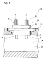
- the liquid type identifying sensor 24 includes a liquid type identifying sensor heater 25 and a liquid temperature sensor 28 provided apart from the liquid type identifying sensor heater 25 at a constant interval.
- the liquid type identifying sensor heater 25 and the liquid temperature sensor 28 are formed integrally by a mold resin 30.
- the liquid type identifying sensor heater 25 includes a lead electrode 32 and a thin film chip portion 34. Moreover, the liquid type identifying sensor heater 25 is provided with a metallic fin 36 protruded into the gasoline liquid type identifying chamber 20 to directly come in contact with the identified gasoline through the opening portion 22 for the liquid type identifying sensor from the mold resin 30.
- the lead electrode 32, the thin film chip portion 34 and the fin 36 are mutually connected electrically through a bonding wire 38.
- the liquid temperature sensor 28 also has the same structure as that of the liquid type identifying sensor heater 25, and includes the lead electrode 32, the thin film chip portion 34, the fin 36 and the bonding wire 38 respectively.
- the thin film chip portion 34 is constituted by a thin film-shaped chip in which a substrate 40 formed of Al 2 O 3 , a temperature sensor (temperature detector) 42 formed of PT, an interlayer insulating film 44 formed of SiO 2 , a heater (heating member) 46 formed of TaSiO 2 , a heating member electrode 48 formed of Ni, a protective film 50 formed of SiO 2 , and an electrode pad 52 formed of Ti/Au are provided in order, for example.
- a substrate 40 formed of Al 2 O 3 a temperature sensor (temperature detector) 42 formed of PT, an interlayer insulating film 44 formed of SiO 2 , a heater (heating member) 46 formed of TaSiO 2 , a heating member electrode 48 formed of Ni, a protective film 50 formed of SiO 2 , and an electrode pad 52 formed of Ti/Au are provided in order, for example.
- the thin film chip portion 34 of the liquid temperature sensor 28 also has the same structure, it is so constituted as not to cause the heater (heating member) 46 to act but to cause only the temperature sensor (temperature detector) 42 to act.
- the identified gasoline is discharged from the gasoline liquid type identifying chamber 20 to an outside through a gasoline discharge port 54.
- the identified gasoline flowing into the first passage 14 through the gasoline inlet 18 then stays temporarily in the alcoholic contents detecting chamber 56.
- alcoholic contents are detected by an alcohol detecting sensor 58 when the gasoline contains alcohol.
- the same gasoline is discharged from the alcohol contents detecting chamber 56 through the gasoline discharge port 54 of the second passage 16. The details of the detection of the alcohol will be omitted in the present example.
- circuit board members connected to the liquid type identifying sensor 24 and the alcohol detecting sensor 58 and lid members for covering them are not shown.
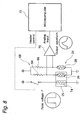
- the apparatus 10 for identifying the liquid type of a gasoline according to the present invention has the structure of a circuit shown in Fig. 8 .
- an identifying liquid temperature sensor 26 of the liquid type identifying sensor heater 25 and the liquid temperature sensor 28 in the liquid type identifying sensor 24 are connected to each other through two resistors 64 and 66, thereby constituting abridge circuit 68.
- the output of the bridge circuit 68 is connected to the input of an amplifier 70, and the output of the amplifier 70 is connected to the input of a computer 72 constituting an identification control portion.
- the applied voltage of a heater 74 of the liquid type identifying sensor heater 25 is controlled under the control of the computer 72.
- the liquid type of the gasoline is identified in the following manner.
- the identified gasoline is caused to flow from the gasoline inlet 18 of the first passage 14 of the apparatus 10 for identifying the liquid type of a gasoline and is caused to stay temporarily in the gasoline liquid type identifying chamber 20 of the second passage 16.
- a pulse voltage P is applied to the heater 74 of the liquid type identifying sensor heater 25 under the control of the computer 72 for a predetermined time, that is, four seconds in the present example. Then, a change in the temperature of the analog output of a sensing portion, that is, the sensor bridge circuit 68 shown in Fig. 8 is measured. More specifically, as shown in Fig. 9 , the voltage difference of the sensor bridge circuit 68 is sampled at a predetermined number of times, for example, 256 times in the present example for one second before the pulse voltage P is applied to the heater 74 of the liquid type identifying sensor heater 25, and an average value thereof is set to be an average initial voltage V1. The value of the average initial voltage V1 corresponds to the initial temperature of the identifying liquid temperature sensor 26.
- the predetermined pulse voltage P that is, a voltage of 10V in the present example is applied to the heater 74 of the liquid type identifying sensor heater 25 for four seconds.
- a value obtained by sampling a peak voltage at a predetermined number of times, for example, 256 times in the present example for one second after a predetermined time, for example, 3 seconds in the present example is set to be an average peak voltage V2.
- the average peak voltage V2 corresponds to the peak temperature of the identifying liquid temperature sensor 26.
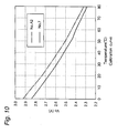
- calibration curve data to be the correlation of a voltage output difference with a temperature are previously obtained for a predetermined reference gasoline, that is, the heaviest gasoline A2 (which rarely evaporates) and the lightest gasoline No. 7 (which easily evaporates) in the present example.
- the obtained calibration curve data are stored in the computer 72 constituting the identification control portion.
- a liquid type voltage output Vout for the voltage output difference V0 at a measuring temperature T of the identified gasoline is correlated with an output voltage for a voltage output difference at a measuring temperature for a predetermined threshold reference gasoline (the gasoline A2 and the gasoline No. 7 in the present example) and is thus corrected.
- a voltage output difference V0-A2 of the gasoline A2 a voltage output difference V0-7 of the gasoline No. 7 and a voltage output difference V0-S of the identified gasoline are obtained at the temperature T based on the calibration curve data.
- the liquid type voltage output Vout of the identified gasoline is obtained by setting the liquid type output of the threshold reference gasoline in this case to have a predetermined voltage, that is, by setting the liquid type output of the gasoline A2 to be 3.5V and the liquid type output of the gasoline No. 7 to be 0.5V in the present example.
- a correlation with the characteristics of the gasoline can be acquired.
- the liquid type voltage output Vout of the identified gasoline is compared with data previously stored in the computer 72 based on the calibration curve data. Consequently, it is possible to identify the liquid type of the gasoline accurately and rapidly (instantaneously).
- the method for identifying the liquid type of a gasoline described above utilizes a natural convection and a principle in which the kinetic viscosity of the gasoline and the sensor output have a correlation.
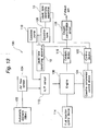
- Fig. 12 is the same schematic diagram as Fig. 14 , illustrating an example in which the apparatus 10 for identifying the liquid type of a gasoline having such a structure is applied to a car system.
- the apparatus 10 for identifying the liquid type of a gasoline is provided in a gasoline tank 108 or on the upstream side of a gasoline pump 110.
- the apparatus 10 for identifying the liquid type of a gasoline identifies the liquid type of a gasoline in the gasoline tank 108 or on the upstream or downstream side of the gasoline pump 110 (the case of the upstream side will be described in the present example for convenience of explanation). Then, the apparatus 10 regulates an ignition timing by an ignition timing control device 122 under the control of a control device 120 depending on the type of the gasoline.
- the ignition timing is controlled to be quickened.
- the ignition timing is controlled to be delayed.
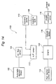
- Fig. 13 is the same schematic diagram as Fig. 14 , illustrating an example in which the apparatus 10 for identifying the liquid type of a gasoline having such a structure is applied to a car system.
- the apparatus 10 for identifying the liquid type of a gasoline is provided in a gasoline tank 108 or on the upstream side of a gasoline pump 110.
- the apparatus 10 for identifying the liquid type of a gasoline identifies the liquid type of a gasoline in the gasoline tank 108 or on the upstream or downstream side of the gasoline pump 110 (the case of the upstream side will be described in the present example for convenience of explanation). Then, the apparatus 10 regulates the compressibility of the gasoline by a gasoline compression control device 124 under the control of a control device 120 depending on the type of the gasoline.
- the compressibility is controlled to be reduced.
- the heavy gasolineA2 which rarely evaporates
- a pulse voltage is applied for a predetermined time. Consequently, it is possible to identify the type of a gasoline accurately and rapidly through heating for a short time without carrying out the heating to such a temperature as to ignite the gasoline.
- the type of the gasoline is identified with the voltage output difference V0 obtained for the identified gasoline, based on calibration curve data to be the correlation of a voltage output difference with a temperature for a predetermined reference gasoline which is prestored. Therefore, it is possible to identify the type of the gasoline more accurately and rapidly.
- a liquid type voltage output Vout for the voltage output difference V0 at the measuring temperature of the identified gasoline is correlated with the output voltage for the voltage output difference at the measuring temperature for a predetermined threshold reference gasoline and is thus corrected. Consequently, it is possible to eliminate the influence of the temperature on the voltage output difference V0, thereby giving the correlation of the liquid type voltage output Vout with the characteristics of the gasoline more accurately. Thus, it is possible to identify the type of the gasoline further accurately and rapidly.
- a mechanism portion for carrying out a mechanical operation is not present. Therefore, an operation failure is not caused by a deterioration with the passage of time, foreign matters in the gasoline or the like. Thus, it is possible to identify the liquid type of the gasoline accurately and rapidly.
- the senor portion can be constituted to be very small-sized. Consequently, it is possible to identify the liquid type of the gasoline accurately with a very excellent thermal responsiveness.
- the heater of the liquid type identifying sensor heater, the identifying liquid temperature sensor and the liquid temperature sensor do not directly come in contact with the identified gasoline. Therefore, an operation failure is not caused by a deterioration with the passage of time, foreign matters in the gasoline or the like. Thus, it is possible to identify the liquid type of the gasoline accurately and rapidly.
- the present invention furthermore, it is possible to identify the type of the gasoline in a car accurately and rapidly and to regulate an ignition timing based on the result of the identification of the type of the gasoline. Consequently, it is possible to obtain a proper ignition timing depending on the type of the gasoline.
- the present invention furthermore, it is possible to identify the type of the gasoline in a car accurately and rapidly and to regulate the compressibility of the gasoline based on the result of the identification of the type of the gasoline. Consequently, it is possible to obtain a proper compressibility of the gasoline depending on the type of the gasoline.
- the present invention can produce various remarkable and peculiar functions and effects, which is very excellent.
Landscapes
- Engineering & Computer Science (AREA)
- Chemical & Material Sciences (AREA)
- Combustion & Propulsion (AREA)
- Mechanical Engineering (AREA)
- General Engineering & Computer Science (AREA)
- Health & Medical Sciences (AREA)
- Oil, Petroleum & Natural Gas (AREA)
- Life Sciences & Earth Sciences (AREA)
- Physics & Mathematics (AREA)
- Immunology (AREA)
- Pathology (AREA)
- General Physics & Mathematics (AREA)
- Chemical Kinetics & Catalysis (AREA)
- Analytical Chemistry (AREA)
- Biochemistry (AREA)
- General Health & Medical Sciences (AREA)
- Medicinal Chemistry (AREA)
- General Chemical & Material Sciences (AREA)
- Food Science & Technology (AREA)
- Electrochemistry (AREA)
- Investigating Or Analyzing Materials Using Thermal Means (AREA)
- Loading And Unloading Of Fuel Tanks Or Ships (AREA)
- Electrical Control Of Ignition Timing (AREA)
- Output Control And Ontrol Of Special Type Engine (AREA)
- Combined Controls Of Internal Combustion Engines (AREA)
Claims (20)
- Appareil (10) permettant d'identifier un type de
liquide d'une essence, comprenant :une chambre d'identification de type de liquide d'une essence (56) pour amener une essence identifiée introduite dans un corps d'appareil d'identification de type de liquide à y rester momentanément ;un dispositif de chauffage capteur d'identification de type de liquide (25) aménagé dans la chambre d'identification de type de liquide d'essence ; etun capteur de température de liquide (28) aménagé dans la chambre d'identification de type de liquide de l'essence séparément du dispositif de chauffage capteur d'identification de type de liquide à un intervalle constant ;le dispositif de chauffage capteur d'identification de type de liquide comprenant un dispositif de chauffage (74) et un capteur de température de liquide identifiant (26) aménagé au voisinage du dispositif de chauffage, etl'appareil comprenant par ailleurs une portion de commande d'identification ;caractérisé en ce que la portion de commande d'identification est conçue de sorte qu'une tension pulsée (P) soit appliquée au dispositif de chauffage capteur d'identification de type de liquide sur une période prédéterminée et que l'essence identifiée restant temporairement dans la chambre d'identification de type d'essence liquide soit chauffée par le dispositif de chauffage et que le type de liquide soit identifié par une différence de sortie de tension V0 correspondant à une différence de température entre une température initiale et un pic de température dans le capteur de température de liquide identifiant. - Appareil permettant d'identifier un type de liquide d'une essence selon la revendication 1, dans lequel la différence de sortie de tension V0 est égale à une différence de tension entre une tension initiale moyenne V1 obtenue par échantillonnage d'une tension initiale avant application de la tension pulsée un nombre prédéterminé de fois et une tension de pic moyenne V2 obtenue par échantillonnage d'une tension de pic après l'application de la tension pulsée un nombre prédéterminé de fois, c'est-à-dire que :

- Appareil permettant d'identifier un type de liquide d'une essence selon la revendication 1 ou la revendication 2, dans lequel la portion de commande d'identification identifie le type d'une essence avec la différence de sortie de tension V0 obtenue pour l'essence identifiée, sur la base de données d'une courbe d'étalonnage qui est censée être une corrélation d'une différence de sortie de tension avec une température pour une essence de référence prédéterminée préstockée dans la portion de commande d'identification.
- Appareil permettant d'identifier un type de liquide d'une essence selon l'une quelconque des revendications 1 à 3, dans lequel la portion de commande d'identification met en corrélation une sortie de tension Vout de type de liquide pour la différence de sortie de tension V0 à une température de mesure de l'essence identifiée avec une tension de sortie pour une différence de sortie de tension à une température de mesure pour une essence de référence de seuil prédéterminé et effectue donc une correction.
- Appareil permettant d'identifier un type de liquide d'une essence selon l'une quelconque des revendications 1 à 3, dans lequel le dispositif de chauffage capteur d'identification de type de liquide est un dispositif de chauffage capteur d'identification de type de liquide laminé, dans lequel un dispositif de chauffage et un capteur de température de liquide identifiant sont laminés à travers une couche isolante.
- Appareil permettant d'identifier un type de liquide d'une essence selon l'une quelconque des revendications 1 à 5, dans lequel le dispositif de chauffage et le capteur de température de liquide identifiant dans le dispositif de chauffage capteur d'identification de type de liquide sont constitués pour venir en contact avec l'essence identifiée via une ailette métallique (32), respectivement.
- Appareil permettant d'identifier un type de liquide d'une essence selon l'une quelconque des revendications 1 à 6, dans lequel le capteur de température de liquide est conçu pour venir en contact avec l'essence identifiée via une ailette métallique (32).
- Procédé permettant d'identifier un type de liquide d'une essence, comprenant les étapes consistant à :appliquer une tension pulsée (P) sur une période prédéterminée à un dispositif de chauffage capteur (25) d'identification de type de liquide, comprenant un dispositif de chauffage (74) et un capteur de température de liquide identifiant (26) aménagé au voisinage du dispositif de chauffage ;chauffer une essence identifiée par le dispositif de chauffage ; etidentifier le type de liquide avec une différence de sortie de tension V0 correspondant à une différence de température entre une température initiale et une température de pic dans le capteur de température de liquide identifiant.
- Procédé permettant d'identifier un type de liquide d'une essence selon la revendication 8, dans lequel la différence de sortie de tension V0 est égale à une différence de tension entre une tension initiale moyenne V1 obtenue par échantillonnage d'une tension initiale avant application de la tension pulsée un nombre prédéterminé de fois et une tension de pic moyenne V2 obtenue par échantillonnage d'une tension de pic après l'application de la tension pulsée un nombre prédéterminé de fois, c'est-à-dire que :

- Procédé permettant d'identifier un type de liquide d'une essence selon la revendication 8 ou la revendication 9, dans lequel un type d'essence est identifié avec la différence de sortie de tension V0 obtenue pour l'essence identifiée sur la base de données de courbe d'étalonnage qui sont censées être une corrélation d'une différence de sortie de tension avec une température pour une essence de référence prédéterminée qui est préstockée.
- Procédé permettant d'identifier un type de liquide d'une essence selon l'une quelconque des revendications 8 à 10, dans lequel une sortie de tension Vout de type de liquide pour la différence de sortie de tension V0 à une température de mesure de l'essence identifiée est en corrélation avec une tension de sortie pour une différence de sortie de tension à une température de mesure pour une essence de référence de seuil prédéterminé et est donc corrigée.
- Procédé permettant d'identifier un type de liquide d'une essence selon l'une quelconque des revendications 8 à 11, dans lequel le dispositif de chauffage capteur d'identification de type de liquide est un dispositif de chauffage capteur d'identification de type de liquide laminé, dans lequel un dispositif de chauffage et un capteur de température de liquide identifiant sont laminés à travers une couche isolante.
- Procédé permettant d'identifier un type de liquide d'une essence selon l'une quelconque des revendications 8 à 12, dans lequel le dispositif de chauffage et le capteur de température de liquide identifiant dans le dispositif de chauffage capteur d'identification de type de liquide sont conçus pour venir en contact avec l'essence identifiée via une ailette métallique (32), respectivement.
- Procédé permettant d'identifier un type de liquide d'une essence selon l'une quelconque des revendications 8 à 13, dans lequel le capteur de température de liquide est conçu pour venir en contact avec l'essence identifiée via une ailette métallique (32).
- Appareil permettant d'identifier un type de liquide d'une essence d'une voiture (100), comprenant :l'appareil permettant d'identifier un type de liquide d'une essence selon l'une quelconque des revendications 1 à 7, qui est aménagé dans un réservoir d'essence (108) ou sur le côté amont ou le côté aval d'une pompe à essence (110).
- Procédé permettant d'identifier un type de liquide d'une essence d'une voiture (100), comprenant l'étape consistant à :identifier un type d'essence dans un réservoir d'essence (108) ou sur le côté amont ou le côté aval d'une pompe à essence (110) en utilisant le procédé permettant d'identifier un type de liquide d'une essence selon l'une quelconque des revendications 8 à 14.
- Appareil de réduction des gaz d'échappement d'une voiture (100), comprenant :l'appareil permettant d'identifier un type de liquide d'une essence selon l'une quelconque des revendications 1 à 7, qui est aménagé dans un réservoir d'essence (108) ou sur le côté amont ou le côté aval d'une pompe à essence (110) ; etun dispositif de commande de réglage d'allumage (122) pour réguler un réglage d'allumage sur la base du type d'essence qui est identifié par l'appareil d'identification d'un type de liquide d'une essence.
- Procédé permettant de réduire les gaz d'échappement d'une voiture (100), comprenant les étapes consistant à :identifier un type d'essence dans un réservoir d'essence (108) ou sur le côté amont ou le côté aval d'une pompe à essence (112) en utilisant le procédé permettant d'identifier un type de liquide d'une essence selon l'une quelconque des revendications 8 à 14, etréguler un réglage d'allumage sur la base du type d'essence qui est identifié par l'appareil d'identification d'un type de liquide d'une essence.
- Appareil permettant de réduire les gaz d'échappement d'une voiture (100), comprenant :l'appareil permettant d'identifier un type de liquide d'une essence selon l'une quelconque des revendications 1 à 7, qui est aménagé dans un réservoir d'essence (108) ou sur le côté amont ou le côté aval d'une pompe à essence (110) ; etun dispositif de commande de compression d'essence pour réguler la capacité de compression de l'essence sur la base du type d'essence qui est identifié par l'appareil d'identification d'un type de liquide d'une essence.
- Procédé de réduction des gaz d'échappement d'une voiture (100), comprenant les étapes consistant à :identifier un type d'essence dans un réservoir d'essence (108) ou sur le côté amont ou le côté aval d'une pompe à essence (110) en utilisant le procédé permettant d'identifier un type de liquide d'une essence selon l'une quelconque des revendications 8 à 14, etréguler la capacité de compression de l'essence sur la base du type d'essence qui est identifié par l'appareil pour identifier un type de liquide d'une essence.
Applications Claiming Priority (3)
| Application Number | Priority Date | Filing Date | Title |
|---|---|---|---|
| JP2002264543 | 2002-09-10 | ||
| JP2002264543A JP3758625B2 (ja) | 2002-09-10 | 2002-09-10 | ガソリンの液種識別装置およびガソリンの液種識別方法 |
| PCT/JP2003/011569 WO2004025287A1 (fr) | 2002-09-10 | 2003-09-10 | Systeme et procede d'identification de type d'essence |
Publications (3)
| Publication Number | Publication Date |
|---|---|
| EP1538438A1 EP1538438A1 (fr) | 2005-06-08 |
| EP1538438A4 EP1538438A4 (fr) | 2011-11-30 |
| EP1538438B1 true EP1538438B1 (fr) | 2014-01-22 |
Family
ID=31986531
Family Applications (1)
| Application Number | Title | Priority Date | Filing Date |
|---|---|---|---|
| EP03795369.2A Expired - Lifetime EP1538438B1 (fr) | 2002-09-10 | 2003-09-10 | Systeme et procede d'identification de type d'essence |
Country Status (5)
| Country | Link |
|---|---|
| US (1) | US7152582B2 (fr) |
| EP (1) | EP1538438B1 (fr) |
| JP (1) | JP3758625B2 (fr) |
| AU (1) | AU2003262058A1 (fr) |
| WO (1) | WO2004025287A1 (fr) |
Families Citing this family (13)
| Publication number | Priority date | Publication date | Assignee | Title |
|---|---|---|---|---|
| WO2005005971A1 (fr) * | 2003-07-11 | 2005-01-20 | Mitsui Mining & Smelting Co., Ltd. | Dispositif et procede de detection de debit/type de liquide et dispositif et procede de detection de type de liquide |
| JP4342855B2 (ja) | 2003-07-11 | 2009-10-14 | 三井金属鉱業株式会社 | 軽油の液種識別装置および軽油の液種識別方法 |
| US7647844B2 (en) * | 2003-07-11 | 2010-01-19 | Mitsui Mining & Smelting Co., Ltd. | Device and method of detecting flow rate/liquid kind, and device and method of detecting liquid kind |
| JP2005201068A (ja) * | 2004-01-13 | 2005-07-28 | Denso Corp | 燃料判別装置 |
| JP3987041B2 (ja) * | 2004-01-30 | 2007-10-03 | 三井金属鉱業株式会社 | 液種識別装置 |
| JP4038492B2 (ja) * | 2004-05-28 | 2008-01-23 | 三井金属鉱業株式会社 | 液種識別方法及び液種識別装置 |
| JP4390066B2 (ja) * | 2004-10-25 | 2009-12-24 | 三井金属鉱業株式会社 | 液位検出方法及び液位検出装置 |
| EP2009431A1 (fr) * | 2006-03-28 | 2008-12-31 | Mitsui Mining and Smelting Co., Ltd | Appareil d'identification de fluide et méthode d'identification de fluide |
| WO2008036630A2 (fr) * | 2006-09-18 | 2008-03-27 | Howard Lutnick | Produits et procédés pour déterminer le taux d'octane |
| EP2037234A1 (fr) | 2007-09-14 | 2009-03-18 | General Electric Company | Détecteur de liquide |
| CN104970881A (zh) * | 2015-07-02 | 2015-10-14 | 安隽医疗科技(南京)有限公司 | 一种射频消融导管以及包含该射频消融导管的治疗装置 |
| US11391307B2 (en) * | 2020-01-21 | 2022-07-19 | Caterpillar Paving Products Inc. | Hydraulic tank protection system |
| DE112023004478T5 (de) * | 2022-10-26 | 2025-09-11 | Robert Bosch Limitada | System und verfahren zur identifizierung von fluiden |
Family Cites Families (13)
| Publication number | Priority date | Publication date | Assignee | Title |
|---|---|---|---|---|
| JPH03262949A (ja) * | 1990-03-13 | 1991-11-22 | Matsushita Electric Ind Co Ltd | 液体種別検知装置 |
| JPH04178550A (ja) * | 1990-11-14 | 1992-06-25 | Hitachi Ltd | 熱式燃料性状センサ |
| JPH0510173A (ja) * | 1991-07-04 | 1993-01-19 | Mitsubishi Electric Corp | 内燃機関の電子制御装置 |
| JP2632460B2 (ja) * | 1991-10-09 | 1997-07-23 | 株式会社ユニシアジェックス | ガソリン性状判別装置 |
| JPH07104305B2 (ja) * | 1992-10-26 | 1995-11-13 | プラネット株式会社 | 欠陥調査装置および欠陥調査方法 |
| US5535614A (en) * | 1993-11-11 | 1996-07-16 | Nok Corporation | Thermal conductivity gas sensor for measuring fuel vapor content |
| US5535615A (en) | 1994-08-10 | 1996-07-16 | International Paper Company | Absorption tester for measuring the wicking characteristics of a paperboard web |
| JPH10170485A (ja) * | 1996-10-08 | 1998-06-26 | Toyota Motor Corp | 超音波式ガソリン特性判別方法および装置 |
| JPH11153561A (ja) * | 1997-11-21 | 1999-06-08 | Mitsui Mining & Smelting Co Ltd | 流体識別方法及び流体識別装置 |
| US5965813A (en) * | 1998-07-23 | 1999-10-12 | Industry Technology Research Institute | Integrated flow sensor |
| JP4050857B2 (ja) * | 1999-04-27 | 2008-02-20 | 矢崎総業株式会社 | 流体判別装置及び流量計測装置 |
| JP2000337207A (ja) * | 1999-05-24 | 2000-12-05 | Mitsubishi Electric Corp | 内燃機関の燃料性状判別装置 |
| JP4316083B2 (ja) * | 1999-12-15 | 2009-08-19 | 三井金属鉱業株式会社 | 流体判別機能を有する熱式流量計 |
-
2002
- 2002-09-10 JP JP2002264543A patent/JP3758625B2/ja not_active Expired - Lifetime
-
2003
- 2003-09-10 WO PCT/JP2003/011569 patent/WO2004025287A1/fr not_active Ceased
- 2003-09-10 US US10/527,302 patent/US7152582B2/en not_active Expired - Lifetime
- 2003-09-10 AU AU2003262058A patent/AU2003262058A1/en not_active Abandoned
- 2003-09-10 EP EP03795369.2A patent/EP1538438B1/fr not_active Expired - Lifetime
Also Published As
| Publication number | Publication date |
|---|---|
| JP3758625B2 (ja) | 2006-03-22 |
| US20060011170A1 (en) | 2006-01-19 |
| EP1538438A4 (fr) | 2011-11-30 |
| EP1538438A1 (fr) | 2005-06-08 |
| JP2004101385A (ja) | 2004-04-02 |
| US7152582B2 (en) | 2006-12-26 |
| WO2004025287A1 (fr) | 2004-03-25 |
| AU2003262058A1 (en) | 2004-04-30 |
Similar Documents
| Publication | Publication Date | Title |
|---|---|---|
| US7971425B2 (en) | Urea concentration identifying system, method for indentifying urea concentration and automobile exhaust gas reducing system using same, and method for reducing automobile exhaust gas | |
| US7647844B2 (en) | Device and method of detecting flow rate/liquid kind, and device and method of detecting liquid kind | |
| EP1548432B1 (fr) | Systeme d'identification d'essences et procede d'identification d'un type de carburant | |
| US7152582B2 (en) | Gasoline type identifying system and method for identifying gasoline type | |
| EP1653227A1 (fr) | Dispositif et procede de detection de debit/type de liquide et dispositif et procede de detection de type de liquide | |
| EP0995986A2 (fr) | Appareil pour mesurer la concentration de gaz | |
| EP1645870B1 (fr) | Systeme d'identification de type de carburant diesel et procede d'identification de type de carburant diesel | |
| JP4405536B2 (ja) | 尿素濃度識別装置および尿素濃度識別方法ならびにそれを用いた自動車の排気ガスの低減装置および自動車の排気ガスの低減方法 | |
| EP2148051B1 (fr) | Appareil de purification des gaz d'échappement pour moteur à combustion interne | |
| US7493802B2 (en) | Liquid type identification device | |
| JP2005030888A (ja) | 流量・液種検知装置および流量・液種検知方法 | |
| JP2001133429A (ja) | 車載用noxセンサのオフセット再校正方法 | |
| US20190136785A1 (en) | Control apparatus for exhaust gas sensor | |
| WO1994027139A1 (fr) | Procede et dispositif de detection de materiaux oxydables dans un espace | |
| JPH0758275B2 (ja) | 酸素センサ | |
| Fosaaen | Development of a Novel Low-Cost, Low-Power, Narrow-Band Oxygen Sensor for Small Engine Applications.(1 of 3) | |
| JPS58501522A (ja) | 酸素センサ用温度制御装置 |
Legal Events
| Date | Code | Title | Description |
|---|---|---|---|
| PUAI | Public reference made under article 153(3) epc to a published international application that has entered the european phase |
Free format text: ORIGINAL CODE: 0009012 |
|
| 17P | Request for examination filed |
Effective date: 20050310 |
|
| AK | Designated contracting states |
Kind code of ref document: A1 Designated state(s): AT BE BG CH CY CZ DE DK EE ES FI FR GB GR HU IE IT LI LU MC NL PT RO SE SI SK TR |
|
| AX | Request for extension of the european patent |
Extension state: AL LT LV MK |
|
| DAX | Request for extension of the european patent (deleted) | ||
| A4 | Supplementary search report drawn up and despatched |
Effective date: 20111028 |
|
| RIC1 | Information provided on ipc code assigned before grant |
Ipc: F02D 41/00 20060101ALI20111024BHEP Ipc: F02M 7/00 20060101ALI20111024BHEP Ipc: G01N 33/28 20060101ALI20111024BHEP Ipc: F02P 5/15 20060101ALI20111024BHEP Ipc: F02D 45/00 20060101ALI20111024BHEP Ipc: F02D 15/00 20060101ALI20111024BHEP Ipc: G01N 27/18 20060101ALI20111024BHEP Ipc: G01N 25/18 20060101AFI20111024BHEP |
|
| 17Q | First examination report despatched |
Effective date: 20130403 |
|
| GRAP | Despatch of communication of intention to grant a patent |
Free format text: ORIGINAL CODE: EPIDOSNIGR1 |
|
| INTG | Intention to grant announced |
Effective date: 20131011 |
|
| RIN1 | Information on inventor provided before grant (corrected) |
Inventor name: TAKAHATA, TAKAYUKI, MITSUI MIN. & SMELTING CO.,LTD Inventor name: YAMAGISHI, KIYOSHI, MITSUI MIN. & SMELTING CO.,LTD Inventor name: KAWANISHI, TOSHIAKI, MITSUI MIN. & SMELTING CO.,LT |
|
| GRAS | Grant fee paid |
Free format text: ORIGINAL CODE: EPIDOSNIGR3 |
|
| GRAA | (expected) grant |
Free format text: ORIGINAL CODE: 0009210 |
|
| RIN1 | Information on inventor provided before grant (corrected) |
Inventor name: TAKAHATA, TAKAYUKI Inventor name: KAWANISHI, TOSHIAKI Inventor name: YAMAGISHI, KIYOSHI |
|
| AK | Designated contracting states |
Kind code of ref document: B1 Designated state(s): AT BE BG CH CY CZ DE DK EE ES FI FR GB GR HU IE IT LI LU MC NL PT RO SE SI SK TR |
|
| REG | Reference to a national code |
Ref country code: GB Ref legal event code: FG4D |
|
| REG | Reference to a national code |
Ref country code: CH Ref legal event code: EP |
|
| REG | Reference to a national code |
Ref country code: AT Ref legal event code: REF Ref document number: 651021 Country of ref document: AT Kind code of ref document: T Effective date: 20140215 |
|
| REG | Reference to a national code |
Ref country code: NL Ref legal event code: T3 Ref country code: IE Ref legal event code: FG4D |
|
| REG | Reference to a national code |
Ref country code: SE Ref legal event code: TRGR |
|
| REG | Reference to a national code |
Ref country code: DE Ref legal event code: R096 Ref document number: 60345664 Country of ref document: DE Effective date: 20140306 |
|
| REG | Reference to a national code |
Ref country code: AT Ref legal event code: MK05 Ref document number: 651021 Country of ref document: AT Kind code of ref document: T Effective date: 20140122 |
|
| PG25 | Lapsed in a contracting state [announced via postgrant information from national office to epo] |
Ref country code: PT Free format text: LAPSE BECAUSE OF FAILURE TO SUBMIT A TRANSLATION OF THE DESCRIPTION OR TO PAY THE FEE WITHIN THE PRESCRIBED TIME-LIMIT Effective date: 20140522 Ref country code: CY Free format text: LAPSE BECAUSE OF FAILURE TO SUBMIT A TRANSLATION OF THE DESCRIPTION OR TO PAY THE FEE WITHIN THE PRESCRIBED TIME-LIMIT Effective date: 20140122 Ref country code: ES Free format text: LAPSE BECAUSE OF FAILURE TO SUBMIT A TRANSLATION OF THE DESCRIPTION OR TO PAY THE FEE WITHIN THE PRESCRIBED TIME-LIMIT Effective date: 20140122 Ref country code: AT Free format text: LAPSE BECAUSE OF FAILURE TO SUBMIT A TRANSLATION OF THE DESCRIPTION OR TO PAY THE FEE WITHIN THE PRESCRIBED TIME-LIMIT Effective date: 20140122 Ref country code: FI Free format text: LAPSE BECAUSE OF FAILURE TO SUBMIT A TRANSLATION OF THE DESCRIPTION OR TO PAY THE FEE WITHIN THE PRESCRIBED TIME-LIMIT Effective date: 20140122 |
|
| PG25 | Lapsed in a contracting state [announced via postgrant information from national office to epo] |
Ref country code: BE Free format text: LAPSE BECAUSE OF FAILURE TO SUBMIT A TRANSLATION OF THE DESCRIPTION OR TO PAY THE FEE WITHIN THE PRESCRIBED TIME-LIMIT Effective date: 20140122 |
|
| REG | Reference to a national code |
Ref country code: DE Ref legal event code: R097 Ref document number: 60345664 Country of ref document: DE |
|
| PG25 | Lapsed in a contracting state [announced via postgrant information from national office to epo] |
Ref country code: CZ Free format text: LAPSE BECAUSE OF FAILURE TO SUBMIT A TRANSLATION OF THE DESCRIPTION OR TO PAY THE FEE WITHIN THE PRESCRIBED TIME-LIMIT Effective date: 20140122 Ref country code: RO Free format text: LAPSE BECAUSE OF FAILURE TO SUBMIT A TRANSLATION OF THE DESCRIPTION OR TO PAY THE FEE WITHIN THE PRESCRIBED TIME-LIMIT Effective date: 20140122 Ref country code: DK Free format text: LAPSE BECAUSE OF FAILURE TO SUBMIT A TRANSLATION OF THE DESCRIPTION OR TO PAY THE FEE WITHIN THE PRESCRIBED TIME-LIMIT Effective date: 20140122 Ref country code: EE Free format text: LAPSE BECAUSE OF FAILURE TO SUBMIT A TRANSLATION OF THE DESCRIPTION OR TO PAY THE FEE WITHIN THE PRESCRIBED TIME-LIMIT Effective date: 20140122 |
|
| PG25 | Lapsed in a contracting state [announced via postgrant information from national office to epo] |
Ref country code: SK Free format text: LAPSE BECAUSE OF FAILURE TO SUBMIT A TRANSLATION OF THE DESCRIPTION OR TO PAY THE FEE WITHIN THE PRESCRIBED TIME-LIMIT Effective date: 20140122 |
|
| PLBE | No opposition filed within time limit |
Free format text: ORIGINAL CODE: 0009261 |
|
| STAA | Information on the status of an ep patent application or granted ep patent |
Free format text: STATUS: NO OPPOSITION FILED WITHIN TIME LIMIT |
|
| 26N | No opposition filed |
Effective date: 20141023 |
|
| REG | Reference to a national code |
Ref country code: DE Ref legal event code: R097 Ref document number: 60345664 Country of ref document: DE Effective date: 20141023 |
|
| PG25 | Lapsed in a contracting state [announced via postgrant information from national office to epo] |
Ref country code: MC Free format text: LAPSE BECAUSE OF FAILURE TO SUBMIT A TRANSLATION OF THE DESCRIPTION OR TO PAY THE FEE WITHIN THE PRESCRIBED TIME-LIMIT Effective date: 20140122 Ref country code: LU Free format text: LAPSE BECAUSE OF FAILURE TO SUBMIT A TRANSLATION OF THE DESCRIPTION OR TO PAY THE FEE WITHIN THE PRESCRIBED TIME-LIMIT Effective date: 20140910 |
|
| REG | Reference to a national code |
Ref country code: CH Ref legal event code: PL |
|
| PG25 | Lapsed in a contracting state [announced via postgrant information from national office to epo] |
Ref country code: SI Free format text: LAPSE BECAUSE OF FAILURE TO SUBMIT A TRANSLATION OF THE DESCRIPTION OR TO PAY THE FEE WITHIN THE PRESCRIBED TIME-LIMIT Effective date: 20140122 |
|
| REG | Reference to a national code |
Ref country code: IE Ref legal event code: MM4A |
|
| REG | Reference to a national code |
Ref country code: NL Ref legal event code: SD Effective date: 20150707 Ref country code: GB Ref legal event code: 732E Free format text: REGISTERED BETWEEN 20150618 AND 20150624 |
|
| PG25 | Lapsed in a contracting state [announced via postgrant information from national office to epo] |
Ref country code: CH Free format text: LAPSE BECAUSE OF NON-PAYMENT OF DUE FEES Effective date: 20140930 Ref country code: LI Free format text: LAPSE BECAUSE OF NON-PAYMENT OF DUE FEES Effective date: 20140930 |
|
| REG | Reference to a national code |
Ref country code: FR Ref legal event code: PLFP Year of fee payment: 13 |
|
| REG | Reference to a national code |
Ref country code: DE Ref legal event code: R081 Ref document number: 60345664 Country of ref document: DE Owner name: SUN-A CORPORATION, MIYOSHI, JP Free format text: FORMER OWNER: MITSUI MINING SMELTING CO., LTD., TOKYO, JP Ref country code: DE Ref legal event code: R082 Ref document number: 60345664 Country of ref document: DE Representative=s name: DEHNS, GB Ref country code: DE Ref legal event code: R081 Ref document number: 60345664 Country of ref document: DE Owner name: SUN-A CORPORATION, MIYOSHI, JP Free format text: FORMER OWNER: MITSUI MINING & SMELTING CO., LTD., TOKYO, JP Ref country code: DE Ref legal event code: R081 Ref document number: 60345664 Country of ref document: DE Owner name: SUN-A CORPORATION, MIYOSHI, JP Free format text: FORMER OWNER: MITSUI MINING & SMELTING CO., LTD., TOKIO/TOKYO, JP |
|
| PG25 | Lapsed in a contracting state [announced via postgrant information from national office to epo] |
Ref country code: IE Free format text: LAPSE BECAUSE OF NON-PAYMENT OF DUE FEES Effective date: 20140910 |
|
| REG | Reference to a national code |
Ref country code: FR Ref legal event code: TP Owner name: MITSUI MINING & SMELTING CO., LTD., JP Effective date: 20150917 |
|
| PG25 | Lapsed in a contracting state [announced via postgrant information from national office to epo] |
Ref country code: BG Free format text: LAPSE BECAUSE OF FAILURE TO SUBMIT A TRANSLATION OF THE DESCRIPTION OR TO PAY THE FEE WITHIN THE PRESCRIBED TIME-LIMIT Effective date: 20140122 |
|
| PG25 | Lapsed in a contracting state [announced via postgrant information from national office to epo] |
Ref country code: IT Free format text: LAPSE BECAUSE OF FAILURE TO SUBMIT A TRANSLATION OF THE DESCRIPTION OR TO PAY THE FEE WITHIN THE PRESCRIBED TIME-LIMIT Effective date: 20140122 Ref country code: GR Free format text: LAPSE BECAUSE OF FAILURE TO SUBMIT A TRANSLATION OF THE DESCRIPTION OR TO PAY THE FEE WITHIN THE PRESCRIBED TIME-LIMIT Effective date: 20140423 |
|
| PG25 | Lapsed in a contracting state [announced via postgrant information from national office to epo] |
Ref country code: HU Free format text: LAPSE BECAUSE OF FAILURE TO SUBMIT A TRANSLATION OF THE DESCRIPTION OR TO PAY THE FEE WITHIN THE PRESCRIBED TIME-LIMIT; INVALID AB INITIO Effective date: 20030910 Ref country code: TR Free format text: LAPSE BECAUSE OF FAILURE TO SUBMIT A TRANSLATION OF THE DESCRIPTION OR TO PAY THE FEE WITHIN THE PRESCRIBED TIME-LIMIT Effective date: 20140122 |
|
| REG | Reference to a national code |
Ref country code: FR Ref legal event code: PLFP Year of fee payment: 14 |
|
| REG | Reference to a national code |
Ref country code: FR Ref legal event code: PLFP Year of fee payment: 15 |
|
| REG | Reference to a national code |
Ref country code: FR Ref legal event code: PLFP Year of fee payment: 16 |
|
| REG | Reference to a national code |
Ref country code: DE Ref legal event code: R082 Ref document number: 60345664 Country of ref document: DE |
|
| PGFP | Annual fee paid to national office [announced via postgrant information from national office to epo] |
Ref country code: NL Payment date: 20220819 Year of fee payment: 20 |
|
| PGFP | Annual fee paid to national office [announced via postgrant information from national office to epo] |
Ref country code: SE Payment date: 20220811 Year of fee payment: 20 Ref country code: GB Payment date: 20220728 Year of fee payment: 20 Ref country code: DE Payment date: 20220803 Year of fee payment: 20 |
|
| PGFP | Annual fee paid to national office [announced via postgrant information from national office to epo] |
Ref country code: FR Payment date: 20220808 Year of fee payment: 20 |
|
| REG | Reference to a national code |
Ref country code: DE Ref legal event code: R071 Ref document number: 60345664 Country of ref document: DE |
|
| REG | Reference to a national code |
Ref country code: NL Ref legal event code: MK Effective date: 20230909 |
|
| REG | Reference to a national code |
Ref country code: GB Ref legal event code: PE20 Expiry date: 20230909 |
|
| PG25 | Lapsed in a contracting state [announced via postgrant information from national office to epo] |
Ref country code: GB Free format text: LAPSE BECAUSE OF EXPIRATION OF PROTECTION Effective date: 20230909 |
|
| REG | Reference to a national code |
Ref country code: SE Ref legal event code: EUG |