EP1540800B1 - Moteur a reducteur planetaire - Google Patents
Moteur a reducteur planetaire Download PDFInfo
- Publication number
- EP1540800B1 EP1540800B1 EP03794730A EP03794730A EP1540800B1 EP 1540800 B1 EP1540800 B1 EP 1540800B1 EP 03794730 A EP03794730 A EP 03794730A EP 03794730 A EP03794730 A EP 03794730A EP 1540800 B1 EP1540800 B1 EP 1540800B1
- Authority
- EP
- European Patent Office
- Prior art keywords
- core
- flexispline
- flexible spline
- motor
- hub
- Prior art date
- Legal status (The legal status is an assumption and is not a legal conclusion. Google has not performed a legal analysis and makes no representation as to the accuracy of the status listed.)
- Expired - Lifetime
Links
- 238000004804 winding Methods 0.000 claims abstract description 90
- 239000002131 composite material Substances 0.000 claims abstract description 15
- 238000010276 construction Methods 0.000 claims abstract description 12
- ATJFFYVFTNAWJD-UHFFFAOYSA-N Tin Chemical compound [Sn] ATJFFYVFTNAWJD-UHFFFAOYSA-N 0.000 claims abstract description 4
- 239000000696 magnetic material Substances 0.000 claims description 15
- 239000000463 material Substances 0.000 claims description 12
- 238000003475 lamination Methods 0.000 claims description 11
- 230000033001 locomotion Effects 0.000 claims description 11
- 229920000642 polymer Polymers 0.000 claims description 6
- 238000012546 transfer Methods 0.000 claims description 6
- 230000000295 complement effect Effects 0.000 claims description 5
- 239000011248 coating agent Substances 0.000 claims description 2
- 238000000576 coating method Methods 0.000 claims description 2
- 239000006247 magnetic powder Substances 0.000 claims description 2
- 230000004907 flux Effects 0.000 abstract description 49
- 230000005284 excitation Effects 0.000 description 13
- 238000005516 engineering process Methods 0.000 description 6
- 230000006870 function Effects 0.000 description 6
- 238000000034 method Methods 0.000 description 6
- 230000008901 benefit Effects 0.000 description 5
- 239000000411 inducer Substances 0.000 description 5
- 238000004080 punching Methods 0.000 description 5
- 230000009467 reduction Effects 0.000 description 5
- 239000007787 solid Substances 0.000 description 5
- XEEYBQQBJWHFJM-UHFFFAOYSA-N Iron Chemical compound [Fe] XEEYBQQBJWHFJM-UHFFFAOYSA-N 0.000 description 4
- 230000005540 biological transmission Effects 0.000 description 4
- 230000008859 change Effects 0.000 description 4
- 230000005672 electromagnetic field Effects 0.000 description 4
- 229910052751 metal Inorganic materials 0.000 description 4
- 239000002184 metal Substances 0.000 description 4
- 125000006850 spacer group Chemical group 0.000 description 4
- 238000011217 control strategy Methods 0.000 description 3
- 230000000694 effects Effects 0.000 description 3
- 238000004519 manufacturing process Methods 0.000 description 3
- 230000005355 Hall effect Effects 0.000 description 2
- PXHVJJICTQNCMI-UHFFFAOYSA-N Nickel Chemical compound [Ni] PXHVJJICTQNCMI-UHFFFAOYSA-N 0.000 description 2
- 238000013459 approach Methods 0.000 description 2
- 238000006243 chemical reaction Methods 0.000 description 2
- 239000012141 concentrate Substances 0.000 description 2
- 238000010586 diagram Methods 0.000 description 2
- 238000009826 distribution Methods 0.000 description 2
- 230000005489 elastic deformation Effects 0.000 description 2
- 229910052742 iron Inorganic materials 0.000 description 2
- 239000000314 lubricant Substances 0.000 description 2
- 230000004048 modification Effects 0.000 description 2
- 238000012986 modification Methods 0.000 description 2
- 239000002887 superconductor Substances 0.000 description 2
- 229910000838 Al alloy Inorganic materials 0.000 description 1
- 229910000531 Co alloy Inorganic materials 0.000 description 1
- 229910000640 Fe alloy Inorganic materials 0.000 description 1
- FYYHWMGAXLPEAU-UHFFFAOYSA-N Magnesium Chemical compound [Mg] FYYHWMGAXLPEAU-UHFFFAOYSA-N 0.000 description 1
- 229910000861 Mg alloy Inorganic materials 0.000 description 1
- 229910000990 Ni alloy Inorganic materials 0.000 description 1
- 229910019142 PO4 Inorganic materials 0.000 description 1
- 229910000676 Si alloy Inorganic materials 0.000 description 1
- 229910000831 Steel Inorganic materials 0.000 description 1
- 230000000712 assembly Effects 0.000 description 1
- 238000000429 assembly Methods 0.000 description 1
- 230000004323 axial length Effects 0.000 description 1
- 238000005266 casting Methods 0.000 description 1
- 239000003795 chemical substances by application Substances 0.000 description 1
- 239000004035 construction material Substances 0.000 description 1
- 238000001816 cooling Methods 0.000 description 1
- 230000008878 coupling Effects 0.000 description 1
- 238000010168 coupling process Methods 0.000 description 1
- 238000005859 coupling reaction Methods 0.000 description 1
- 230000001747 exhibiting effect Effects 0.000 description 1
- 238000009730 filament winding Methods 0.000 description 1
- 230000020169 heat generation Effects 0.000 description 1
- 230000006698 induction Effects 0.000 description 1
- 238000009434 installation Methods 0.000 description 1
- XWHPIFXRKKHEKR-UHFFFAOYSA-N iron silicon Chemical compound [Si].[Fe] XWHPIFXRKKHEKR-UHFFFAOYSA-N 0.000 description 1
- 238000005461 lubrication Methods 0.000 description 1
- 239000011777 magnesium Substances 0.000 description 1
- 230000013011 mating Effects 0.000 description 1
- 238000005259 measurement Methods 0.000 description 1
- 239000012528 membrane Substances 0.000 description 1
- 239000000203 mixture Substances 0.000 description 1
- 230000007659 motor function Effects 0.000 description 1
- 230000003534 oscillatory effect Effects 0.000 description 1
- 239000002245 particle Substances 0.000 description 1
- 230000035699 permeability Effects 0.000 description 1
- NBIIXXVUZAFLBC-UHFFFAOYSA-K phosphate Chemical compound [O-]P([O-])([O-])=O NBIIXXVUZAFLBC-UHFFFAOYSA-K 0.000 description 1
- 239000010452 phosphate Substances 0.000 description 1
- 239000012256 powdered iron Substances 0.000 description 1
- 230000008569 process Effects 0.000 description 1
- 230000002250 progressing effect Effects 0.000 description 1
- 238000007493 shaping process Methods 0.000 description 1
- 239000010703 silicon Substances 0.000 description 1
- 239000010959 steel Substances 0.000 description 1
- 239000000126 substance Substances 0.000 description 1
Images









Classifications
-
- H—ELECTRICITY
- H02—GENERATION; CONVERSION OR DISTRIBUTION OF ELECTRIC POWER
- H02K—DYNAMO-ELECTRIC MACHINES
- H02K41/00—Propulsion systems in which a rigid body is moved along a path due to dynamo-electric interaction between the body and a magnetic field travelling along the path
- H02K41/06—Rolling motors, i.e. motors having the rotor axis parallel to the stator axis and following a circular path as the rotor rolls around the inside or outside of the stator ; Nutating motors, i.e. having the rotor axis parallel to the stator axis inclined with respect to the stator axis and performing a nutational movement as the rotor rolls on the stator
-
- F—MECHANICAL ENGINEERING; LIGHTING; HEATING; WEAPONS; BLASTING
- F16—ENGINEERING ELEMENTS AND UNITS; GENERAL MEASURES FOR PRODUCING AND MAINTAINING EFFECTIVE FUNCTIONING OF MACHINES OR INSTALLATIONS; THERMAL INSULATION IN GENERAL
- F16H—GEARING
- F16H49/00—Other gearings
- F16H49/001—Wave gearings, e.g. harmonic drive transmissions
Definitions
- This invention relates to a high torque low speed motor, which as part of its construction contains an electromagnetic permeable cup, which is elastically distorted by the influence of an electromagnetic field.
- This cup has the classical shape of an open-ended tin can in which a cylinder and generally an end disc are integrally connected.
- the open end of the cylinder incorporates a band gear having radially extending teeth, which is also capable of undergoing elastic deformation as the cylinder of the cup is deformed.
- the open end of the cup on which the band gear is located is made to contact a gear in close proximity to the cup (which gear does not undergo any significant distortion) and which is contacted by said gear for example at two opposing points at the ends of the major axis of the elliptical shape assumed by the cup and band gear combination, or the protruding nodes of the other shapes.
- the band gear and the contacting gear have teeth, which mesh; both sets of teeth have the same pitch but differ in number.
- the radially extending teeth of the band gear progressively engage different teeth of the contacting gear; and because of the differing number of teeth on the two gears, relative rotation of the two gears occurs.
- This gearing phenomenon is well known and is usually referred to as strain wave gearing.
- An alternative form of construction embodies a composite material flexible spline (flexispline) of open cylinder form, open both ends, and rotatively fixed by means of integral male longitudinal splines. These splines mate into similar female splines formed in the circumferential surface of the internal electromagnetic core, this allows band gear teeth radial movement but prevents flexispline rotation, while permitting significantly greater torque transfer with a low distributed pressure. This mating spline arrangement may also be applied beneficially to the one closed end cup construction of paragraph 1 above.
- strain wave gearing or flexible spline (flexispline) drives are well known and are discussed in U. S. Patents 2,906, 143 (September 29,1959 ) and 2,931, 248 (April 15,1960) issued to Musser .
- There the underlying principles involving the continuous oscillatory contact of a flexible spline (flexispline) with a ring gear to produce a rotational output from the ring gear are discussed in some detail.
- a torque is produced in the ring gear by the continuous elastic deformation of the flexible spline's gear tooth ring by a cam device called a strain inducer to cause the teeth on the flexispline to be driven into sequential engagement with the teeth of the ring gear.
- the ring gear is forced to rotate a distance equal to the small tooth difference (generally two teeth for elliptical distortion) between the flexispline and the ring gear for one revolution of the strain inducer.
- the output torque is developed from the continuous sequential meshing of the teeth of the flexispline with the ring gear and is proportional to the inverse of the gear ratio. This torque is generated by the rotating strain inducer, which is constantly distorting the flexispline to engage the ring gear in a sequential manner.
- the size and shape of the unit may change, but the continuous sequential multilobe distortion of a flexible cylinder is always present to produce output rotational motion at modified speeds and torques. It is a prime objective of the present invention to extend the application of this electromagnetically driven flexispline technology into applications requiring significantly greater and efficient output torque and power.
- This invention relates to a low speed high torque motor, which contains as part of its construction a magnetically permeable sleeve (flexispline).
- the sleeve in its non-deformed shape is cylindrical, but when under the influence of an electromagnetic field becomes distorted into an multi-lobed shape.
- Both the flexispline and the stator core of the motor remain rotationally stationary during operation of the unit.
- the sleeve itself is preferably anchored to a cylindrical electromagnetic core by means of a bolted flange arrangement or interlocking splines, which facilitate torque transmission and prevent rotation of the sleeve, but allow it to undergo a cross-sectional shape distortion from a circle to the multi-lobed shape.
- the electromagnetic core preferably is provided with a series of axially extending grooves (slots) on its surface which lock into complementary splines on the inside of the surface of the flexispline sleeve.
- the grooves of this magnetic core may also house the stator windings which produce the electromagnetic field in the motor.
- gear teeth which may be integrally formed in the sleeve surface or it may be a band fixed to the surface of the sleeve by some acceptable means.
- the band gear is also distorted by flexing motion of the sleeve to undergo the same distortion as the sleeve, and is preferably constructed from low elastic-modulus materials, such as polymer composite or hard coated magnesium or aluminium alloy.
- the band gear of the sleeve meshes with another gear which, at rest, preferably is spaced very close to but not necessarily engaging the band gear.
- the band gear and the enclosed gear have the same tooth pitch, but the tooth number are deliberately made to be different for the two gears.
- the sleeve Upon excitation of the electromagnetic core, the sleeve undergoes wave distortion as does the band gear, and the distortion of the band gear causes the band gear teeth to engage the teeth of the other gear at corresponding points. As the distorted sleeve shape sweeps about the other gear, the tooth engagement progresses around the said gear and because of the difference in the number of teeth on the two gears, the said output gear rotates in greatly reduced motion, with respect to the rotating excitation magnetic field.
- the flexispline and the stator core comprise an electromagnetic system for which a rotating magnetic field is generally produced by a set of preferably inverted stator windings placed inside the flexispline which in turn produces a magnetic flux to distort the flexispline.
- the stator windings are carried by the central core or that part of a conventional electric motor which is usually occupied by the rotor.
- These stator windings may be formed using superconducting cooled wire such as provided by American Superconducting Corporation.
- the stator core comprises a body of laminated magnetic material or its equivalent to enhance the concentration of the magnetic field produced by a set of windings carried by the stator core.
- stator core windings are made to produce and concentrate a rotating magnetic flux which preferably passes from the core, across an airgap, then into the flexispline, splits, and returns to the core.
- This magnetic flux preferably is produced by passing a programmed commutated modulated current through the core windings.
- the resultant magnetic flux produces a rotating concentrated radially directed force of variable speed.
- the stator core itself is preferably mounted on a sturdy stationary central post which may be hollow and comprised of an electrically resistive (ohmic) magnetic material which serves to provide a rigid mounting means for the ring gear hub and any external load carried by the hub at the end of the post.
- the hub is mounted on the post so that the ring gear provided in the hub enjoys a close concentric relationship with the stator core and the flexispline.
- a set of thrust bearings assures that the coaxial relationship of the core and the ring gear is maintained during rotation of the hub.
- the hub may be connected to an output shaft or a screw actuator to produce rotational or linear motion. It may also be mounted within a wheel of a vehicle to provide power to drive the wheel. When the device of this invention is mounted within a wheel, the shaft may also support the cantilevered vehicle load on the extended shaft and bearings, thus reducing an equivalent parts count.
- This patent describes a flexispline motor having an external stator (which is stationary) comprising a number of circumferentially distributed salient poles (axially aligned solenoid pole pairs) having an adjacent ring gear also mounted in the stator adjacent the poles.
- a flexispline rotor is attached to a shaft and is mounted for rotation within the stator and is provided with external gear teeth on the exterior surface thereof to mesh with a ring gear encircling the flexispline.
- the flexispline rotor is provided with a series of radial magnetically permeable axially aligned laminations mounted under its surface and allowed to pivot about one end (acting as a lever). These laminations are fastened to a rotor fulcrum ring and encouraged to pivot when subjected to a radial magnetic, force. A substantial mechanical advantage results.
- the laminations Upon actuation by a sequentially pulsed rotating magnetic field, the laminations pivot outwardly to cause the flexispline to distort and contact the surrounding ring gear. This causes rotation of the flexispline rotor and its attached shaft (in a direction opposite the direction of the rotating magnetic field). The rotor thus moves in accordance with the tooth differential existing between the ring gear and the flexispline gear giving rise to substantially reduced rotational motion at the output.
- a stator is supplied with a set of windings to produce a rotating magnetic field.
- the stator comprises a series of stacked laminations which not only serve to provide a mounting system for the windings but also serve to provide a surface for attaching a stationary c-axial ring gear in the air gap between the stator and the flexispline rotor.
- the stationary ring gear has internally extending teeth which are engaged by the flexispline rotor externally extending teeth as it is distorted by a rotating magnetic field.
- the flexispline rotor in this instance is a thin (which limits the magnetic flux through it) flexible magnetically permeable hollow cylinder having ends closed by membranes which support and allow deflection of the cylinder but limits the magnetic flux flow through it.
- a shaft is made to pass through the central axis thereof.
- the closed ends of the flexispline cylinder are fastened to the shaft so that any rotation of the flexispline is transferred to the central shaft.
- the rotating flexispline is provided with a gear which is mounted or formed in the surface thereof to contact the internally extending teeth of the stationary ring gear.
- the magnetic flux produced by the stator windings passes into and returns from the hollow flexispline tube to produce a magnetic attraction force.
- the circular shape of the cylindrical flexispline tube is distorted outwardly to force the teeth of the flexispline into engagement with the teeth of the stationary ring gear.
- the flexispline rotor thus rotates according to the tooth differential of the two sets of meshing gears, but in the opposite direction to the rotating magnetic field.
- the major focus of this patent is to produce a biased coiled magnetically permeable flat strip within the flexispline rotor to enhance the magnetic attraction between the flexispline and the stator and to reduce edge effect discontinuities which effect the position controlaccuracy in a servomotor positioning application.
- This patent describes a flexispline motor having a fixed external stator in which conventional three phase induction windings and a stationary ring gear are mounted.
- a flexispline having pockets of powdered iron arranged beneath its surface is influenced by a rotating magnetic field to distort under the attractive force of that field. This causes engagement of the flexispline gear with the stationary ring gear to produce motion in accordance with the tooth differential of the flexispline gear and the ring gear.
- This patent proposes the use of a tapered coil of flat flexible magnetic material beneath the flexispline to enhance elasticity and magnetic force attraction of the flexispline.
- the magnetic material is strategically slotted axially to decrease eddy current circulation.
- This patent is an excellent example of the state-of-the-art electrically driven vehicle in which a drive motor is located within the wheel and is connected through a double reduction gear transmission to produce a high driving torque.
- This relatively recent patent describes a driving assembly for a wheel, in which low torque requirements are produced by an inside-out motor where the stator carries permanent magnets.
- This patent describes a driving arrangement for the wheel of a very large off-the-road vehicle.
- a DC motor drives the wheel through a double reduction gear train.
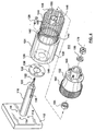
- wheel motor 10 is shown as a cross section view in Fig. 1 and as an exploded view in Fig. 3.
- the motor 10 is mounted on base plate 12, which in this illustration is provided with four threaded holes 14. The number of threaded holes depends on the application; there may be more or less holes 14 depending on the required output.
- a sturdy post 16 (which is preferably hollow, magnetic and of a high ohmic resistance) is mounted on base plate 12 so as to project orthogonally therefrom.
- Post 16 is provided with keyway 18 and wheel bearing mounting segment 20. Post 16 terminates in a threaded end 22.
- a somewhat cup-shaped flexible sleeve 24 (flexispline) is mounted on base plate 12 between a pair of spacers 26 by means of screws 28 so that it may not rotate.
- Sleeve 24 has a closed end 30 (which may be of somewhat heavier construction than the cylindrical upstanding portion 32) which is integrally attached to end 30.
- Sleeve 24 has an open end 34 remote from end 30.
- the end 30 of flexispline 24 has a locating hole 36 provided therein to guide the flexispline along post 16 during installation, and the opening 36 serves to centre and locate the flexispline 24 on base 12 so that the holes 38 and 40 in the spacers 26 and end 30 of flexispline 24 may be easily aligned with threaded holes 14 of base plate 12 for ease of assembly and to maintain gearing tolerances.
- the cylindrical upstanding portion 32 of flexispline 24 is provided with an external toothed gear 42 at or near the end 34 of flexispline 24.
- the flexispline 24 (in this instance) is composed of a highly permeable magnetic material having a high magnetic saturation level, as well as exhibiting a high resistance to eddy current circulation.
- a suitable material for flexispline 24 for this application would be iron or iron alloys including steel silicon, nickel and/or cobalt alloys (such as Carpenter HyperCo 15).
- the cylindrical shell 32 is purposely made to be radially distorted so that its usual shape (that is to say, its undeformed and undistorted shape-which is a cylinder) may be distorted to take on a multi-lobed shape (when compelled by the magnetic force to change from its normal shape).
- the flexispline 24 is mounted on base plate 12 by sliding it along post 16 until holes 38 and 40 line up with threaded holes 14. Countersunk screws 28 are threaded through holes 38 and 40 into the threaded holes 14 to hold the flexispline 24 firmly between spacers 26 against base 12.
- a magnetic core 44 is slid into place on post 16 and is rigidly mounted and located on post 16 in its home position and held in this location (in this instance) by means of key 46 in keyway 18.
- a corresponding keyway (not shown) is formed in core 44 to complement the keyway 18 formed in post 16.
- Core 44 is supplied with a winding 48 which is wound in core slots 50 formed in the surface of core 44 in such a manner as to provide the rotating magnetic field when energized. This field ultimately causes the flexure of the wall 32 of flexispline 24.
- a switched reluctance motor type field winding (for example four phase two rotor pole, or six and three phase with three rotor poles) along with appropriate control circuitry and communtation, such as depicted in Figures 31 and 32, may be used to provide the necessary deflection of the sleeve 32 of flexispline 24.
- the field winding may also be comprised of cooled superconducting wire as manufactured by American Superconductor Corporation USA.
- hub 52 (on which a vehicle wheel may be mounted) is rotatably journalled on post 16 by means of thrust bearings 54,56 which are mounted on bearing segment 20 of post 16.
- hub 52 is a robust casting having a similar shape to a truck or automobile wheel hub and brake drum assembly.
- Hub 52 is provided with a pair of bearing recesses to receive a pair of thrust bearings 54 and 56 therein to assure that hub 52 is firmly locked into position and rotates concentrically with the axis of post 16.
- Cylindrical shell 60 of hub 52 is provided with a cantilevered shell portion 62 which is provided with an internal spline gear 64.
- Gear 64 is made to have teeth which mesh with the teeth of spline gear 42 of flexispline 24 but the teeth comprising gear 64 are intentionally made to be different in number than the teeth in spline gear 42, but having the same pitch.
- Hub 52 may be provided with a series of studs such as 66 for mounting a wheel rim thereon.
- motor 10 is represented in cross section as taken along the axis of post 16, showing the distortion of flexispline 24 as the magnetic flux rotates about the axis of motor 10. Note that core 44 and flexispline 24 are rotationally stationary, but gear 64 is forced to rotate in the same direction as the rotating magnetic field.
- the magnetic material comprising flexispline 24 is attracted to core 44 at the points where the magnetic flux emanating from core 44 is greatest. At a point lagging by 90° mechanical the interior surface of flexispline 24 is usually designed to be in close proximity to the exterior surface of core 44.
- the rotating elliptical shape of flexispline 24 may in time produce wear on the surface of core 44 even though flexispline 24 and core 44 have no rotational motion (both are stationary). Flexispline teeth 42 oscillates about their own axis with a very small amplitude.
- Core 44 may be fabricated from electrical iron laminations stacked to the desired length, or core 44 may be a composite, having finely divided particles of a magnetic material encapsulated in a polymeric substance. The latter composite provides a material having good magnetic permeability characteristics, while providing excellent resistance to the flow of three dimensional eddy currents.
- the composite core just described also provides a surface in which it is quite possible to incorporate a solid lubricant to reduce frictional losses (which leads to less production of heat in the core), and also to help dampen any vibrations due to system resonances.
- Fig. 2 shows the modification of the device of Fig. 1 wherein the ring gear (62 of Fig. 1) is equivalent to gear 162 located on the interior of flexispline 124.
- the core 144 is provided with winding 148 to provide the magnetic attraction of flexispline 124 toward core 144.
- the basic difference in operation of the devices of Figs. 1 and 2 is that the flexispline 24 of Fig. 1 contacts the ring gear 62 at an angle of 90° from the point of maximum flux force produced by core 44, whereas the point of contact of flexispline 124 (Fig. 2) with ring gear 162 is coincident with the maximum flux force produced by winding 148 on core 144 in Fig. 2. This results in approximately 10% reduction in required flexispline deflection force for the same defleciton.
- Figs. 4 and Figs. 6A, 6B, 6C similarly describe the motor 110 of Fig. 2.
- Figs. 7 and 8 show an enhancement for the devices of Figs. 1 & 2.
- Figs. 7 and 8 are identical to the components shown in Fig. 1 and Fig. 2.
- a flexispline 224 is mounted on base 212.
- Core 244 carrying winding 248 is mounted on post 216 and locked in place with key 246.
- Winding 280 in this instance is shown having a circular cross section and is wound as a helix around flexispline 224.
- the winding 280 comprises a magnetic material to enhance the magnetic attraction of the flexispline 224 to core 244, to minimize the generation of eddy currents, and to increase flux flow area.
- it is important to control the winding tension in such a manner so as to maximize the locked in radially stress (or pressure). This intern reduces the required flexispline distortion force.
- the winding 280 may be wound and bound to the surface of the flexispline as in a filament winding process or as a preformed coil, which acts as the flexispline. In either case the objective is to minimize the stiffness of the flexispline-coil combination (to keep the distortions stiffness down to a acceptable level, whilst maximizing the area for the flow of magnetic flux).
- the wire comprising the winding 280 may have a square or rectangular cross section.
- Suitable compositions for the wire or tape comprising winding 280 are; Carpenter's silicon iron B, HyperCo 15, or Honeywell amphorous metal 2605C0.
- the turns of winding 280 should be insulated (preferably on the axial facing only) from each other to reduce eddy current flow in winding 280, usually the polymer binding formed on the turns comprising winding 280 is sufficient for this purpose. If not, an oxide or phosphate can be added to same. Note that there is no electrical continuity between the wire layers because the wire ends at both ends of the flexispline 224 and thus forms an open circuit.
- the distortion stiffness of the combined metal flexispline 224 and winding 280 may be reduced by a factor of 3 or more in comparison with an equivalent solid metal flexispline.
- increasing the helical wire-winding angle will also reduce the distortion stiffness of the flexispline.
- a flexispline motor 310 which is a modification of the flexispline motor 10 of Fig. 1, is shown having a composite cup 324 in Fig. 9.
- the cup 324 is composed of a composite of magnetic powder filled polymer or a polymer bound wire or tape wound magnetic material bonded to flange 345, which now functions as a torque transmission agent and fulcrum (lever pivot point) for the electromagnetic deflection of flexispline 324.
- the open-ended flexispline cup concept of Figs. 28,29, 30 may be adapted.
- a set of locking pads 370 and braking pads 372 are shown for arresting motion of the flexispline 324 and rotation of hub 352 if required.
- reference number 70, 170, 270 shows a nut for retaining the bearings.
- a flexispline motor 410 is shown mounted on base 412.
- a quill 416 is firmly mounted on base 412.
- a magnetic core 444 is securely mounted on quill 416 by means of key 446.
- Field excitation windings 448 are wound on core 444.
- flexispline 424 is firmly attached to baseplate 412 by means of spacers 426 and screws 428 as to be coaxial with quill 416 in its rest position.
- a band gear 442 which encircles the open end of flexispline 424 on the exterior surface thereof.
- a driven element 452 is mounted in bearings 454 and 456 inside quill 416.
- Driven element 452 comprises a disc 470 attached to shaft 472 which extends through base 412 to form sharp projection 474, and disc 470 may carry wheel studs such as 476 or a shaft extension such as 478 (in the absence of studs 476).
- This construction allows the flexispline motor 410 to be adaptable to drive a load from either or both ends simultaneously.
- An overwrap winding similar to winding 280 may be incorporated into the structure of flexispline 424 to improve its magnetic characteristics.
- the motor structure may take the form of the flexispline motor in Fig. 2 wherein the flexispline 424 would surround the ring gear.
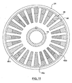
- Fig. 11 is a representation of the Section 6-6 shown in Fig. 1.
- the flexispline 24 is shown surrounding the core 44.
- Three windings 48a, 48b and 48c comprise winding 48. This is a three phase, sinusoidally-distributed, winding, which is a traditional winding.
- the three phase windings 48a, 48b and 48c are distributed about the core 44 in a well-known manner. This winding, will serve to deflect the flexispline in the manner described previously.
- Variable speed and torque control of this winding version can be achieved by means of commercially-available modified electronic A. C. induction-motor controllers. However, the resulting output power, torque and efficiency tend to be disappointing.
- Fig. 12 shows the flux distribution for a flexispline motor having a polyphase two pole winding such as Fig. 11 excited by a sinusoidal signal.
- the core 44 is surrounded by a flexispline 24 (and in this instance an additional flux return path is provided by outer cylindrical core 45).
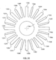
- Fig. 13 shows a core punching 1344 having an even number of core teeth but the teeth of the punching are shown having variable widths.
- Core teeth 1350, 1352, 1354, 1356, 1358, 1360, 1362, and 1364 each have two teeth such as 1366 and 1368 interspersed there between.
- the core 1344 is symmetrical in that this pattern is repeated throughout the core 1344.
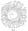
- Fig. 14 shows core 1344 having a four phase 2 pole, reluctance motor type winding wound thereon which will be excited by a switched D. C. 4 phase excitation having each coil separated by 45° mechanical.
- Tooth 1352 is supplied with a winding 1400 which surrounds only the tooth 1352.
- Winding 1400 is connected in a series bucking relationship (to ensure opposite magnetic flux flow directions) with winding 1402 on opposing tooth 1360. These windings are energized between terminals A-A1.
- a pair of windings 1404 and 1406 are wound on core 1344 to encompass teeth 1368, 1352, 1370 and 1384, 1360, 1386 respectively. These windings are energized simultaneously with windings 1400 and 1402 to produce more concentrated flux in the area of teeth 1352 and 1360.
- the other three pole pairs are energized in 45 degree increments sequentially to move the flux pattern around through 180° to cause a wave deflection of the flexispline.
- Fig. 15 shows the flux flow pattern for the coils 1400, 1404, 1402 and 1406 on dumbbell shaped non variable width core teeth 1352, 1368, 1370, 1360, 1384 and 1386 being fully energized with the coils surrounding teeth 1350, 1366, 1396, 1380, 1358 and 1382 being partially energized.
- the flux flow pattern is completely different from that illustrated in Fig. 12.
- the greatest concentration of flux is in teeth 1352 and 1360 which is shown linking adjacent teeth 1350 and 1358 instead of passing through the core hub as shown in Fig. 12.
- the dumbbell shaped core teeth reduce the pole tip magnetic flux density and thus reduce the applied flexispline delfection force in a major way. For these reasons variable width straight teeth are the preferred embodiment.
- Fig. 1 The energizing current for the coils is illustrated schematically in Fig.
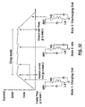
- This current wave form is a switched DC current produced for each set of pole pair windings such as 1400, 1404, 1402, 1406 which produces a gradual rotational distortion of the surrounding flexispline. Without the overlap of the various phase currents in the windings of the core as shown in Fig. 16 the distortion of the flexispline tends to occur in discrete steps. Additionally, this overlap (phase advance) has to increase with increasing output rotational speed to compensate for the field coil flux build up time constant. Of much greater importance however, is the current cut off point (current pulse trailing edge), when the field coil current reverses direction to discharge stored energy this results in negative torque and the current must be cut off.
- the appropriate control strategy is shown in Fig. 32 resulting in a truncated current waveform. This control strategy is effected by the circuitry of Fig. 31, accompanied by appropriate commutation signals generated for instance by Hall effect devices.
- the frequency and amplitude of the various currents should be controlled to adjust the speed and radial force of the distortion wave of the flexispline.
- Suitable circuitry in block diagram form adaptable to achieve such control is shown in Figs. 31 A, 31 B, 31 C, 31 D (Ref. Texas Instrument Literature in BARA058 July 1997)
- windings such as 1400, 1402, 1404, 1406, etc., will function to cause the desired continuous wave distortion of the flexispline 24 of the motors 10, 110 and 210.
- windings such as 1400, 1402, 1404, 1406, etc.
- there are some more less expensive windings which are capable of producing the distortion of the flexispline with less input energy to the magnetic system, and are adaptable to 2,3, or 4 lobe flexispline distortion.
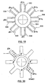
- Fig. 17 shows a magnetic core 524 for a flexispline motor application such as shown in Figs. 1,2, 7 and 8 in which the core is energized in a completely different manner than the core coil system shown in Fig. 11.
- Fig. 17 represents a partial perspective of a core to be used in a Switched Reluctance type Magnetic System.
- the core 524 comprises a hub 526 and spokes 528 arranged in a spaced configuration comprising stacks of laminations to produce, in this instance, a magnetic core having eight poles.
- Fig. 18 shows a typical winding coil 530 for any of the legs 528 of the core 524. Winding 530 is made to slip over the selected leg 528 of core 524.
- Each pole 528 is fitted with a formed coil such as 530.
- a formed coil such as 530.
- eight such coils 530 placed over the individual legs of the core 524, for four or eight phase excitation, and two or four flexispline rotor poles (similarly six coils/poles for three phase excitation with two or three rotor poles).
- Such arrangements allow the potential for electromagnetic gear change ratio on the fly.
- Fig. 19 shows the core 524 having coils 530 placed over each leg; note the wiring sequence.
- Coil 530 which is placed on the ⁇ A leg of core 524 produces flux in the opposite direction as its series connected mate ⁇ A1.
- the actual winding configuration for 2 poles is shown more simplistically in Fig. 20.
- the magnetic flux produced in legs ⁇ A and the ⁇ A1 is in direct opposition in the core.
- the remaining pairs of the six remaining poles are connected in pairs in a similar manner to ⁇ A and ⁇ A1. With each successive pole coil pair being wound in opposite magnetic flux flow directions to the previous pair.
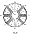
- Fig. 21 is a representation of the flux produced in the four phase switched reluctance core 524. Note how the flux produced in the ⁇ A and ⁇ A1 legs of core 524 is in direct opposition. The flux produced in the ⁇ A divides and splits to link the ⁇ B and ⁇ D1 legs. Similarly the flux produced in the ⁇ A1 let splits and links the ⁇ D leg and ⁇ B1 leg. None of the flux produced in the ⁇ A leg links the ⁇ A1 leg as in the conventional sinusoidally distributed winding illustrated in Fig. 11, thus reducing magnetic flux saturation requirements. However it is obvious from Fig. 21 that the flexispline thickness should be increased to accommodate flux flow density similar to the core teeth.
- Energization of the coils ⁇ A, ⁇ B, ⁇ C, ⁇ D is straightforward.
- the complementary coils ⁇ A and ⁇ Al are connected in series opposition, as are the balance of the coils.
- a four phase switched D.C. power supply is therefore required to produce a magnetic field which results in the production of a continuously moving distortion of the flexispline.
- the power supply should have both magnitude and frequency control to produce an output suitable for driving the flexispline motor for variable speed operation.
- appropriate commutation as shown in Fig. 32.
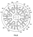
- Fig. 22 shows a representation of a double core switched reluctance type flexispline motor 600.
- an inner core 624 is provided with eight protruding poles (similar to core 524) numbered 632, 634,636, 638,640, 642, 644 and 646.
- Poles 632-646 are energized in exactly the same manner as poles ⁇ A- ⁇ D etc. of Fig. 19 with coils 648-660 being energized so that the flux produced in opposing poles (such as 636 and 644) is bucking.
- All the flexispline motors illustrated in Figs. 1,2, 7,8, and 14 are provided with a core contained within the flexispline itself.
- the flexispline motor 600 is provided with an external core 670 which is composed of a series of stacked laminations which are formed into a unitary structure by techniques well known in the art.
- Core 670 is provided with eight poles 672-686 which face poles 632-646.
- Poles 672-686 are provided with coils 688-704.
- Flexispline 610 is mounted coaxially with and midway between the poles 632-646 and 672-686.
- coils 692 and 700 are simultaneously energized to produce a magnetic pull (spaced 90° mechanically) on the flexispline 610 mounted between the cores 624 and 670.
- the poles 692 and 700 are in space quadrature with poles 648 and 656. While poles 648 and 656 pull the flexispline 610 inwardly, poles 692 and 700 pull the flexispline outwardly to increase the force of engagement of the flexispline 610 with its associated ring gear (not shown).
- This arrangement also permits the coupling of a flexispline having 2 sets of band gears, one on the inside, and one on the outside of the flexispline to engage an internal ring gear and an external ring gear simultaneously.
- the exterior core 670 should be securely mounted on a base (such as 12 in Fig. 1) to hold the exterior core 670 in coaxial alignment with interior core 624 and flexispline 610.
- This arrangement will serve to increase the force of engagement of the flexispline and its associated ring gear.
- This double excitation arrangement will also function with the control strategy of Fig. 31 and Fig. 32. All that is required is an exterior core, the poles of which produce a magnetic field in space quadrature with the field produced by the interior core 48. This provides the necessary distortion of flexispline 610.
- Fig. 23 is a representation of a pull-pull flexispline motor having a six phase, three pole pull-pull type excitation, which is also capable of four or two pole excitation.
- Motor 800 is provided with a flexispline 810, and an inner core 824 having twelve protruding poles (similar to core 624) numbered 846-868.
- Surrounding flexispline 810 is a stationary stator core 870 having poles 872-894 protruding inwardly therefrom.
- Poles 846-868 are provided with windings 896-918 and poles 872-894 are provided with windings 920-942 respectively.
- the flexispline 810 assumes a round shape and the gear teeth (not shown) of flexispline 810 which are integral with flexispline 810 do not engage the ring gear (not shown in Fig. 23).
- the flexispline 810 assumes a circular shape in the unexcited state.
- Fig. 24 illustrates the resultant shaping of flexispline 810 when one of the four phases is energized.
- inner poles 848,856 and 864 are energized by windings 898,906 and 914 so as to deflect flexispline 810 inwardly, while outer poles 876,884 and 892 carrying windings 924,932 and 940 respectively distort the flexispline outwardly to produce a tri-mode engagement with the flexispline 810 and its ring gear or gears.
- Fig. 25 shows the energization of the next phase when coils 900,908 and 916 of inner poles 850,858 and 866 are energized.
- Fig. 26 shows the energization of the six poles of the next phase and the resulting distortions of the flexispline 810.
- the distortion of the flexispline moves through 120 space degrees for the successive sequential energization of four poles.
- Energization of the respective poles is provided by using chopped pulses of dc such as shown in Fig. 27.
- dc such as shown in Fig. 27.
- circuitry of Fig. 31, Fig. 32 and appropriate commutation signals If the tooth differential between the flexispline and the ring gear (assume the ring gear is external to the flexispline) is 3, then for 1 complete excitation mode excursion through 360 deg (space) there are 2 cycles of energization of each coil of the motor 800. This will advance the ring gear by 3 teeth during one excursion of the tricornal shape of the flexispline.
- the various flexispline motors have generally embodied a cup shaped flexispline arrangement (a cylinder with one end open the other end closed).
- the main function of this cylinder is to transfer the full output load reaction torque from the band gear 42 (ref. Fig. 1) back to the base plate 12 (Fig. 1), in addition to facilitating elliptical or tricornal distortion of same.
- This function requires the cylinder (flexispline) to possess adequate shear stiffness (thickness) in order to transfer the output load torque.
- This in turn, along with the closed cup end generally increases the flexispline distortion resistance, which in turn reduces output torque and efficiency.
- Fig. 28 shows the essential component parts of flexispline motor 10A.
- a core 12A is mounted in a frame (not shown) which prevents rotation of core 12A.
- Core 12A may be composed of a stack of stamped laminations or it may be a composite, cast of magnetic material.
- the core 12A is provided with a shaft 15A having ends 14A and 16A at due opposite ends of core 12A.
- Shaft end 14A is fixed so as to maintain core 12A stationary.
- Core 12A has a series of protruding ribs 18 formed in the surface thereof separated by valleys 20A.
- the ribs 18A and the valleys 20A form a spline on which the sleeve type flexispline 22A is received in a spline engaging arrangement.
- the valleys 20A may also serve to house the windings necessary for the production of the electromagnetic field in the core.
- Flexispline 22A which is of the form of a hollow cylinder has internal flexible ribs 24A (preferably of a polymeric based material) and valleys 26A which mate with valleys 20A and ribs 18A of the core 12A.
- the fit between the flexispline 22A and the core is somewhat loose to permit the required flexing of the flexispline in a radial direction, but prevents motion of the flexispline 22A in a circumferential direction.
- This technique can also be used with one closed end cup type flexispline
- An internal band gear 30A is fitted into one end of flexispline 22A so as to be integral therewith.
- the band may be bonded to the sleeve type flexispline 22A or permanently fastened to the sleeve flexispline by some acceptable method.
- band gear 30A and the sleeve type flexispline be capable of the required distortion in the presence of a rotating magnetic field established in core 12A, in order to distort from a circular cross section to a multinodal shape in order to achieve proper operation of motor 10A.
- construction materials having an, elliptical low apparent elastic modulus for both the flexispline and the band gear is a necessity to achieve optimum operation of the motor 10A.
- Fig. 29 shows a cross section of the final assembly of motor 10A.
- the shaft end 14A is permanently fixed to a reference to support motor 10A.
- Shaft 14A is not permitted to turn.
- Coil windings 32A are shown on core 12A and are generally located in valleys (core slots) 20A.
- a fulcrum and retaining ring 34A is generally provided near the end of sleeve type flexispline 22A to establish and stabilize the rest position of the flexispline 22A on core 12A.
- a gear 36A is mounted on an assembly 38A for rotation on shaft 16 of motor 10A.
- Gear 36A has external teeth 40A to engage with the band gear teeth 42A.
- the teeth 42A of band gear 30A do not necessarily engage the teeth 40A of gear 36A under rest conditions.
- the gear assembly 38A is mounted on bearings 44A for efficient rotation.
- Gear assembly 38A terminates in output shaft 46A.
- Core 12A is permanently fixed to the shaft 14A-16A by means of key 50A.
- the motor functions as follows.
- a rotating magnetic field is established in core 12A by windings 32A.
- the magnetic attraction established by the magnetic field in core 12A attracts the magnetic sleeve type flexispline 22A so that opposite sides of the flexispline are drawn inwardly so that band gear 30A contacts the teeth 40A of gear 36A at two diametrically opposed points.
- the gear 36A rotates (according to the tooth differential) in a direction opposite to the rotating magnetic flux.
- the ring 34A which may be fitted into sleeve 22A and core 12A by means of a circumferential groove and flange serves as a hinge, if desired for the flexure of the flexispline 22 on core 12 during operation.
- the flexispline 22A may be made of a composite magnetic material, and or it may be a magnetic metallic cylinder over wound with a magnetic wire or magnetic tape contained therein to enhance its magnetic characteristics while not increasing substantially to the stiffness of the sleeve. This contruction has been described previously.
- the motor 10A of Fig. 29 can be reconfigured as the arrangement 101 of Fig. 30 to place the angular thrust roller bearings 44A inboard of the magnetic core 12A, and to reduce the magnitude of any off-centred load.
- the band gear 301 is placed on the external surface of the flexispline 22A, and the teeth 401 are placed on the internal surface of gear 36A.
- Fig. 30 is the potential placement of a rim 501, and tire 601, assembly for traction vehicle applications, and in-wheel arrangements in particular. Elements of this arrangement are also applicable to the motors 10 (Fig. 1), 110 (Fig. 2), 210 (Fig. 7), 210 (Fig. 8), 310 (Fig. 9), and 410 (Fig. 10). It is also intended that some of the features of motors 10 Fig. 29, and 101 Fig. 30 can be interchanged beneficially.
- the flexispline motor of this invention preferably places the electro-magnetic core inside the flexispline, and minimizes the flux flow path and flexispline stiffness. This concentrates the radial distortion force and maximizes the flexispline flux flow area.
- This construction has definite advantages over prior art devices in that the motor may produce greater torque and power and be much smaller and less complicated than previous devices.
- the torque and power efficiency produced by a flexispline motor depends to a large extent on the square of the diameter of the flexispline.
- the flexispline is surrounded by an electro-magnetic core structure; and or motor casing, thus the diameter of the flexispline is much less than the external diameter of the motor structure.
- the applicant's structure generally places the flexispline at the outer extremities of the motor thus increasing the torque versus motor size ratio significantly, and reducing flexispline stiffness thus increasing efficiency when compared to prior art motors.
- the structure of the flexispline motor of this application is ideally suited for applications such as traction motor, robot joint, and snow blower auger drives, because of compactness, requisite high torque at low speed, capability and the capacity to free wheel when the magnetic core is unexcited.
- Another application relates to hybrid automobile drives, and particularly, in retrofit situations, by placing in-wheel drives at the rear end of front wheel drive vehicles.
- Extension of the technology to large power dissipation devices is envisaged by means of forced cooling and the use of superconducting wire field windings, such as that produced by American Super Conductor Corporation.
- the flexispline motor places an electro-magnetic core both inside and outside of the flexispline, this allowing tricornal distortion of same. This has an advantage in some applications requiring smaller gear ratios and greater stiffness.
- the utilization of the composite flexispline embodying a magnetic filament or tape winding reduces the radial distortion stiffness whilst maximizing the return path magnetic flux flow area. This improves the power output by increasing the torque and improving the efficiency of the subject devices.
- SR switched-reluctance
- the poles in the flexispline motor can be regarded as equivalent to the poles in an SR motor, and it is recognised that the commutation of a flexispline motor is similar enough to that of a SR motor, that the flexispline motor can take advantage of the modified existing well-developed SR commutation technologies.
- Figs. 31 A, 31 B, 31 C, 31 D show how the typical text-book manner of commutating a SR motor may be applied to a flexispline motor.
- Fig. 32 depicts the commutation strategy. This is achieved generally by means of Hall effect magnetic sensing devices for rotor (flexispline) position and or parametic measurements of idle phase winding inductance as in Fig. 31 D. Such technology is an integral and necessary element for efficient operation of the flexispline motor of this patent specification.
Landscapes
- Engineering & Computer Science (AREA)
- General Engineering & Computer Science (AREA)
- Chemical & Material Sciences (AREA)
- Combustion & Propulsion (AREA)
- Electromagnetism (AREA)
- Power Engineering (AREA)
- Mechanical Engineering (AREA)
- Physics & Mathematics (AREA)
- Connection Of Motors, Electrical Generators, Mechanical Devices, And The Like (AREA)
- Iron Core Of Rotating Electric Machines (AREA)
- Dry Shavers And Clippers (AREA)
- Control Of Motors That Do Not Use Commutators (AREA)
- Control Of Electric Motors In General (AREA)
- Linear Motors (AREA)
- Harvester Elements (AREA)
- Telephone Function (AREA)
- Nonmetallic Welding Materials (AREA)
Claims (20)
- Moteur (10, 210, 410, 101) à cannelure souple, comprenant un moyen de support (12/16, 212/216, 412/416, 15A), un premier noyau électromagnétique cylindrique (44, 244, 444, 624, 824, 12A), une cannelure souple (24, 224, 424, 610, 810, 22A) et un moyen formant moyeu pouvant être mis en rotation (52, 252, 452, 38A) monté sur ledit moyen de support, en une relation de fonctionnement,
ledit premier noyau électromagnétique étant prévu avec un premier ensemble d'enroulements (48, 248, 448, 32A) qui conviennent afin de produire un champ magnétique rotatif commuté et commandé,
ladite cannelure souple comprenant une portion de disque (30, 230, 430, 34A) et une portion cylindrique (32, 232) jointes ensemble de manière solidaire pour former la forme générale d'une boîte à extrémité ouverte montée sur ledit moyen de support de telle manière qu'elle entoure ledit premier noyau électromagnétique et est en relation coaxiale avec ledit premier noyau électromagnétique,
ladite portion cylindrique de ladite cannelure souple comprenant un matériau magnétiquement perméable et élastiquement déformable et étant en relation étroitement espacé avec ledit premier noyau mais ne touchant pas forcément ledit premier noyau dans un état magnétique non excité,
ladite cannelure souple ayant un moyen formant bande d'engrenage à dents externes (42, 242, 442, 30A) formé sur celle-ci sous la forme d'une bande élastiquement déformable encerclant la surface extérieure de ladite portion cylindrique généralement prêt de l'extrémité ouverte de ladite cannelure souple,
ledit moyen formant moyeu monté sur ledit moyen de support de façon adjacente à et de manière coaxiale avec ladite cannelure souple, ledit moyen formant moyeu ayant un moyen formant couronne d'engrenage externe complémentaire (64, 264, 36A) recouvrant, mais étroitement espacé de, ledit moyen formant bande d'engrenage sur ladite cannelure souple,
ledit moyen formant bande d'engrenage et ledit moyen formant couronne d'engrenage ayant des dents qui s'engrèneront mais diffèrent en nombre et étant en relation étroitement espacés, mais ne se touchant pas forcément dans un état magnétique non activé,
dans lequel ladite extrémité ouverte de ladite cannelure souple et ledit moyen formant bande d'engrenage étant déformé en présence d'un champ magnétique dans ledit premier noyau afin de former une forme générale à plusieurs lobes de telle manière que ledit moyen formant bande d'engrenage sur ladite cannelure souple présente une mise en prise par dents avec ledit moyen formant couronne d'engrenage sur ledit moyen formant moyeu au niveau desdits lobes en saillie vers l'extérieur sur la forme déformée ainsi formée. - Moteur à cannelure souple (Flexispline) (110, 210, 310, 10A) comprenant un moyen de support (112/116, 212/216, 312/316, 15A), un premier noyau électromagnétique cylindrique (144, 244, 344, 624, 824, 12A), une cannelure souple (124, 224, 324, 610, 810, 22A) et un moyen formant moyeu pouvant être mis en rotation (152, 252, 352, 38A) monté sur ledit moyen de support en relation de fonctionnement,
ledit premier noyau électromagnétique étant prévu avec un premier ensemble d'enroulements (148, 248, 348, 32A; qui conviennent afin de produire un champ magnétique rotatif commuté,
une cannelure souple (Flexispline) comprenant une portion de disque (130, 230, 345, 34A) et une portion cylindrique (132, 232, 332) jointes ensemble de manière solidaire afin de former la forme générale d'une boîte à extrémité ouverte montée sur ledit moyen de support de telle manière qu'elle entoure ledit premier noyau électromagnétique et est en relation coaxiale avec ledit premier noyau électromagnétique,
ladite portion cylindrique de ladite cannelure souple comprenant en outre un matériau magnétiquement perméable et élastiquement déformable et étant en relation étroitement espacée avec ledit premier noyau mais ne touchant pas forcément ledit premier noyau dans un état magnétique non excité,
ladite cannelure souple (Flexispline) ayant un moyen formant bande d'engrenage à dents externes (142, 242, 342, 30A) et élastiquement déformable formé sur celle-ci sur la surface intérieure de ladite portion cylindrique sous la forme d'une bande, près de l'extrémité ouverte de ladite cannelure souple,
ledit moyen formant moyeu monté sur ledit moyen de support de façon adjacente à et s'étendant de manière coaxiale avec ladite cannelure souple, ledit moyen formant moyeu ayant un moyen formant couronne d'engrenage à dents externes complémentaires (164, 264, 364, 36A) formé sur celui-ci au niveau d'une de ses extrémités,
ledit moyen formant couronne d'engrenage étant encerclé par ledit moyen formant bande d'engrenage à dents internes élastiquement déformable de ladite cannelure souple, ledit moyen formant couronne d'engrenage et ledit moyen formant bande d' engrenage étant en relation étroitement espacée, mais ne se touchant pas forcément dans un état magnétique non activé,
ledit moyen formant bande d'engrenage et ledit moyen formant couronne d'engrenage ayant des dents qui s'engrèneront mais différeront en nombre et étant en relation étroitement espacé, mais ne se touchant pas forcément dans un état magnétique non activé,
dans lequel ledit moyen formant bande d'engrenage interne est déformé lors de la présence d'un champ magnétique dans ledit premier noyau pour adopter une forme à plusieurs lobes et entrer en contact avec ledit moyen formant couronne d'engrenage au niveau des lobes en saillie vers l'intérieur de la forme à plusieurs lobes ainsi formés. - Moteur (410) à cannelure souple selon la revendication 1, comprenant en outre un moyen formant arbre (472),
ledit moyen de support comprenant une base (412) et un montant creux (416) relié à ladite base,
ledit moyen formant arbre monté à l'intérieur dudit montant sur des paliers (454, 456) qui conviennent pour une mise en rotation à l'intérieur dudit montant et passant à travers ladite base (474),
ledit moyen formant moyeu (452) connecté audit moyen formant arbre au niveau d'une extrémité opposée à ladite base ;
ledit moyen formant arbre étant accessible au niveau des deux extrémités du moteur. - Moteur à cannelure souple selon la revendication 2, comprenant en outre un moyen formant arbre,
ledit moyen de support comprenant une base et un montant creux relié à ladite base,
ledit moyen formant moyeu pouvant être mis en rotation monté sur ledit moyen formant arbre au niveau d'un point intermédiaire à une extrémité opposée de ladite base,
ledit moyen formant arbre monté sur un moyen formant palier qui convient à l'intérieur dudit montant, passant à l'intérieur dudit montant creux et dudit premier noyau électromagnétique, ledit moyen formant arbre étant accessible au niveau des deux extrémités dudit moteur. - Moteur à cannelure souple selon l'une quelconque des revendications 1 à 4, dans lequel ladite cannelure souple (Flexispline) est enveloppée par enroulement d'une bande magnétiquement perméable (280) ou d'une hélice d'un matériau en fil magnétiquement perméable ou un collier à ajustage fretté (281) afin de produire une pression et une contrainte radiale-radiale compressives immobilisées.
- Moteur à cannelure souple selon l'une quelconque des revendications 1 à 5, dans lequel ladite cannelure souple comprend un revêtement dur sur ledit moyen formant bande d'engrenage pour améliorer des caractéristiques d'usure.
- Moteur à cannelure souple selon l'une quelconque des revendications 1 à 5, dans lequel ladite cannelure souple est composée d'un composite de polymère chargé de poudre magnétique ou d'un matériau magnétique enroulé en fil ou en bande à liaison polymère, conjointement avec la bande d'engrenage.
- Moteur à cannelure souple selon l'une quelconque des revendications 1 à 5, dans lequel ledit premier noyau électromagnétique (624) comprend un noyau magnétiquement perméable d'un moyeu et une construction à rayons,
ledit premier noyau comprend des stratifications empilées ou un composite équivalent afin de former une structure unitaire ayant un nombre paire de pôles à profil rectangulaire espacés radialement autour dudit moyeu,
ledit premier ensemble d'enroulements comprend un enroulement ajusté à chaque pôle destiné à produire un champ magnétique dans chaque pôle,
et les enroulements sur chaque paire de pôles en opposition sur ledit moyeu sont activés afin de produire des champs magnétiques qui s'opposent entre eux. - Moteur à cannelure souple selon l'une quelconque des revendications 1 à 8, dans lequel les enroulements de chaque paire de pâles en opposition sur ledit moyeu sont raccordés en série.
- Moteur à cannelure souple selon l'une quelconque des revendications 1 à 5, dans lequel le premier noyau électromagnétique (524) comprend une série de stratifications empilées, empilées ensemble afin de former un noyau unitaire ayant une configuration à moyeu (526) et à rayons (528), de telle manière qu'un nombre pair de pattes (528) de noyau à profil rectangulaire s'étendent radialement depuis ledit moyeu de premier noyau selon des intervalles espacés de manière égale,
ledit premier ensemble d'enroulements comprend un moyen formant bobine (530) sur chaque patte,
chaque bobine est activée séquentiellement à partir d'une source d'énergie électrique qui convient pour produire un champ magnétique rotatif dans ledit premier noyau,
et les forces magnétiques produites dans chaque paire de pattes de noyau en opposition sont en relation de compensation. - Moteur à cannelure souple selon la revendication 10, dans lequel le nombre de pattes de noyau est de huit,
et la source d'énergie électrique est une source tétraphasée ayant une commande de fréquence, d'amplitude et de commutation des formes d'onde de courant de sortie,
et les bobines sur chaque ensemble de groupes associés de pattes de noyau sont raccordées à ladite source d'énergie électrique dans une relation de compensation en série et en parallèle. - Moteur à cannelure souple selon l'une quelconque des revendications 1 à 5, dans lequel ledit premier noyau (1344) comprend une configuration circulaire et ayant une série de dents à profil rectangulaire s'étendant radialement en saillie depuis ledit premier noyau, lesdites dents ayant des dents (1350, 1352, 1354, 1356, 1358, 1360, 1362, 1364, 1366, 1368, 1370, 1372, 1374, 1376, 1378, 1380, 1382, 1384, 1386, 1388, 1390, 1392, 1394, 1396) de largeurs variables agencées en une séquence régulière autour de la circonférence dudit premier noyau séparées par des fentes de largeur uniforme.
- Moteur à cannelure souple selon l'une quelconque des revendications 1 à 5, dans lequel ledit premier noyau électromagnétique comprend une pile de stratification magnétiquement perméable agencée afin de former un noyau sensiblement cylindrique, ledit premier noyau ayant une série de dents de forme rectangulaire en saillie (1350, 1352, 1354, 1356, 1358, 1360, 1362, 1364, 1366, 1368, 1370, 1372, 1374, 1376, 1378, 1380, 1382, 1384, 1386, 1388, 1390, 1392, 1394, 1396) ayant deux largeurs distinctes séparées par des fentes de largeur égale, et dans lesquelles des dents de largeur moindre (1366, 1368, 1370, 1372, 1374, 1376, 1378, 1380, 1382, 1384, 1386, 1388, 1390, 1392, 1394, 1396) sont égales au double du nombre de dents de largeur plus large (1350, 1352, 1354, 1356, 1358, 1360, 1362, 1364).
- Moteur à cannelure souple selon l'une quelconque des revendications 1 à 5, dans lequel chaque dent de noyau de largeur plus large (1352, 1360) est prévue avec une première bobine (1400, 1402) et une bobine secondaire (1404, 1406) est faite afin d'encercler ladite première bobine plus les dents de largeur moindre sur les deux côtés de ladite dent de premier noyau de largeur plus large.
- Moteur (10A) à cannelure souple selon la revendication 1 ou la revendication 3, dans lequel ledit premier noyau (12A) a la forme générale d'un cylindre ayant une surface extérieure cannelée,
ladite cannelure souple (22A) a la forme d'un cylindre creux ayant une surface cylindrique intérieure ayant une cannelure formée dans ladite surface intérieure afin de s'accoupler avec ladite surface extérieure cannelée dudit premier noyau dans une relation de coulissement qui permet une flexion dans une direction radiale et un transfert de couple mais qui ne permet pas le déplacement de ladite cannelure souple dans une direction circonférentielle. - Moteur (10A) à cannelure souple selon la revendication 2 ou 4, dans lequel ledit premier noyau (12A) a la forme générale d'un cylindre ayant une surface extérieure cannelée, ladite cannelure souple (22A) a la forme d'un cylindre creux ayant une surface cylindrique intérieure ayant une cannelure formée dans ladite surface intérieure destinée à s'accoupler avec ladite surface extérieure cannelée dudit premier noyau dans une relation de coulissement qui permet une flexion dans une direction radiale et un transfert de couple, mais qui ne permet pas le déplacement de ladite cannelure souple dans une direction circonférentielle,
ladite cannelure souple a une extrémité de chevauchement s'étendant au-delà dudit premier noyau, ledit moyen formant bande d'engrenage interne est monté sur ladite extrémité de chevauchement de ladite cannelure souple dans une relation coaxiale avec ledit premier noyau et ladite cannelure souple. - Moteur (10A) à cannelure souple selon la revendication 15 ou 16, dans lequel ladite portion de disque de ladite cannelure souple est une couronne d'appui et de retenue (34A) prévue près de l'extrémité de ladite cannelure souple (22A) afin d'établir et stabiliser la cannelure souple sur ledit premier noyau (12A).
- Moteur à cannelure souple selon l'une quelconque des revendications 1 à 5, comprenant en outre un second noyau électromagnétique (670, 870) et un second ensemble d'enroulements montés sur celui-ci,
ledit second noyau électromagnétique monté sur ledit moyen de support étant coaxial avec ledit premier noyau (624, 824),
ladite cannelure souple (610, 810) étant entourée par ledit second noyau électromagnétique (670, 870) afin d'être localisé de manière coaxiale entre ledit premier noyau électromagnétique (624, 824) et ledit second noyau électromagnétique (670, 870), dans une relation étroitement espacée avec lesdits premier et second noyaux mais ne touchant pas lesdits noyaux en l'absence d'un champ magnétique, ladite cannelure souple ayant l'extrémité ouverte s'étendant axialement au-delà desdits noyaux,
le moyen formant bande d'engrenage étant monté sur une surface prédéterminée au niveau de la partie d'extension de ladite cannelure souple et coaxial avec ladite cannelure souple,
lesdits premier et second ensembles d'enroulements dans lesdits premier et second noyaux sont activés afin d'établir deux champs magnétiques rotatifs en quadrature spatiale. - Appareil formant générateur de force motrice, destiné à convertir une énergie électrique délivrée en mouvement mécanique de rotation d' un moteur, l'appareil comprenant :le moteur (10, 110, 210, 310, 410, 10A, 101) selon l'une quelconque des revendications 1 à 18,un commutateur destiné à recevoir l'énergie électrique délivrée et destiné à orienter celle-ci vers les enroulements, de manière spécialisée, activant et désactivant de ce fait les enroulements, l'énergie non utilisée moins certaines pertes étant renvoyée vers la source d'énergie ;un dispositif de mise en fonctionnement cyclique destiné à mettre en fonctionnement le commutateur pour activer et désactiver les enroulements de manière séquentielle selon un modèle de rotation optimale ;l'agencement de l'appareil étant tel que la mise en fonctionnement du commutateur selon le modèle de rotation est efficace pour entraîner la mise en rotation de la configuration à lobes de la cannelure souple (Flexispline) élastique.
- Appareil formant générateur de force motrice selon la revendication 19, dans lequel l'enroulement de champ de stator dudit moteur à cannelure souple comprend un fil formé d'un matériau supraconducteur creux.
Applications Claiming Priority (3)
| Application Number | Priority Date | Filing Date | Title |
|---|---|---|---|
| GBGB0221070.6A GB0221070D0 (en) | 2002-09-11 | 2002-09-11 | Flexispline motor |
| GB0221070 | 2002-09-11 | ||
| PCT/CA2003/001328 WO2004025815A1 (fr) | 2002-09-11 | 2003-09-11 | Moteur a reducteur planetaire |
Publications (2)
| Publication Number | Publication Date |
|---|---|
| EP1540800A1 EP1540800A1 (fr) | 2005-06-15 |
| EP1540800B1 true EP1540800B1 (fr) | 2007-07-18 |
Family
ID=9943860
Family Applications (1)
| Application Number | Title | Priority Date | Filing Date |
|---|---|---|---|
| EP03794730A Expired - Lifetime EP1540800B1 (fr) | 2002-09-11 | 2003-09-11 | Moteur a reducteur planetaire |
Country Status (8)
| Country | Link |
|---|---|
| US (1) | US7453176B2 (fr) |
| EP (1) | EP1540800B1 (fr) |
| AT (1) | ATE367679T1 (fr) |
| AU (1) | AU2003266042A1 (fr) |
| CA (1) | CA2538716C (fr) |
| DE (1) | DE60315044T2 (fr) |
| GB (1) | GB0221070D0 (fr) |
| WO (1) | WO2004025815A1 (fr) |
Cited By (2)
| Publication number | Priority date | Publication date | Assignee | Title |
|---|---|---|---|---|
| WO2011060881A1 (fr) * | 2009-11-18 | 2011-05-26 | Audi Ag | Réducteur harmonique |
| WO2022108635A1 (fr) * | 2020-08-12 | 2022-05-27 | Joby Aero, Inc. | Actionneur rotatif à entraînement harmonique compact décalé par moteur à rotor externe et système de déploiement l'utilisant |
Families Citing this family (57)
| Publication number | Priority date | Publication date | Assignee | Title |
|---|---|---|---|---|
| GB0221070D0 (en) * | 2002-09-11 | 2002-10-23 | Davison Ernest | Flexispline motor |
| US7049916B2 (en) * | 2004-01-21 | 2006-05-23 | Keihin Corporation | Electromagnetic apparatus |
| EP1764530B1 (fr) * | 2004-07-02 | 2012-03-28 | Honda Motor Co., Ltd. | Mecanisme d'entrainement avec reducteur de vitesse |
| US7527130B2 (en) * | 2005-04-29 | 2009-05-05 | Delphi Technologies, Inc. | Harmonic drive linear actuator |
| US20060283289A1 (en) * | 2005-06-16 | 2006-12-21 | Baudendistel Thomas A | Harmonic drive motor with flex-spline interlock |
| DE102006022543A1 (de) * | 2006-05-15 | 2007-11-22 | Harmonic Drive Ag | Vorrichtung zum Verformen und gegebenenfalls Ausbiegen wenigstens eines Bauteils eines Getriebes, insbesondere Spannungswellengetriebes, im Getriebebetrieb sowie das Getriebe und Verfahren zu dessen Betrieb |
| US7414504B2 (en) * | 2006-06-14 | 2008-08-19 | Datacard Corporation | Laminated solenoid plunger for solenoid assembly |
| US8353854B2 (en) | 2007-02-14 | 2013-01-15 | Tibion Corporation | Method and devices for moving a body joint |
| CA2595196C (fr) * | 2007-07-18 | 2011-02-22 | Michael Christopher Warachka | Transporteur d'equipement a assembler a configurations multiples |
| US7598683B1 (en) | 2007-07-31 | 2009-10-06 | Lsi Industries, Inc. | Control of light intensity using pulses of a fixed duration and frequency |
| US8903577B2 (en) | 2009-10-30 | 2014-12-02 | Lsi Industries, Inc. | Traction system for electrically powered vehicles |
| US8604709B2 (en) | 2007-07-31 | 2013-12-10 | Lsi Industries, Inc. | Methods and systems for controlling electrical power to DC loads |
| DE102007058605B4 (de) * | 2007-12-04 | 2014-06-18 | Wittenstein Ag | Antriebseinheit für die Antriebstechnik mit hoher Leistungsdichte mit zumindest einer Übersetzungsstufe |
| WO2009071604A1 (fr) * | 2007-12-05 | 2009-06-11 | Abb Research Ltd | Moteur harmonique |
| US8052629B2 (en) | 2008-02-08 | 2011-11-08 | Tibion Corporation | Multi-fit orthotic and mobility assistance apparatus |
| US20090306548A1 (en) | 2008-06-05 | 2009-12-10 | Bhugra Kern S | Therapeutic method and device for rehabilitation |
| US8274244B2 (en) * | 2008-08-14 | 2012-09-25 | Tibion Corporation | Actuator system and method for extending a joint |
| US8639455B2 (en) | 2009-02-09 | 2014-01-28 | Alterg, Inc. | Foot pad device and method of obtaining weight data |
| DE102009023080B4 (de) * | 2009-05-28 | 2020-11-26 | Minebea Mitsumi Inc. | Elektrische Maschine |
| DE112009004842B4 (de) * | 2009-06-02 | 2023-06-01 | Harmonic Drive Systems Inc. | Linearbewegungsmechanismus vom Welltyp |
| US8146886B2 (en) * | 2009-08-04 | 2012-04-03 | Honeywell International Inc. | High accuracy, zero backlash rotary-to-linear electromechanical actuator |
| US8033742B1 (en) * | 2010-04-15 | 2011-10-11 | Chapman/Leonard Studio Equipment, Inc. | Telescoping camera crane |
| US9101884B2 (en) * | 2010-02-18 | 2015-08-11 | NAB & Associates, Inc. | Enhanced spiral-wound membrane filtration |
| US10033233B2 (en) * | 2010-06-25 | 2018-07-24 | The Board Of Regents, The University Of Texas System | Double saliency exterior rotor switched reluctance machine with increasing and decreasing flux linkages and permanent magnets |
| US10312782B2 (en) | 2010-06-25 | 2019-06-04 | The Board Of Regents, The University Of Texas System | Double stator permanent magnet machine |
| CA2760454C (fr) | 2010-12-03 | 2019-02-19 | Pratt & Whitney Canada Corp. | Element de confinement de rotor turbine a gaz |
| TWI452803B (zh) * | 2011-06-21 | 2014-09-11 | Ind Tech Res Inst | 電磁變速馬達 |
| PL2732535T3 (pl) * | 2011-07-14 | 2019-06-28 | Jean I. TCHERVENKOV | Zespół kołowy określający silnik elektryczny/generator |
| JP5408212B2 (ja) * | 2011-09-07 | 2014-02-05 | 株式会社安川電機 | 作業用ロボットおよび加工設備 |
| CN108843760A (zh) | 2012-05-25 | 2018-11-20 | 詹尼斯高级技术有限公司 | 变速装置 |
| JP5442162B1 (ja) * | 2012-05-31 | 2014-03-12 | 株式会社ハーモニック・ドライブ・システムズ | 波動歯車装置および可撓性外歯歯車 |
| CN102820762B (zh) * | 2012-06-19 | 2014-10-29 | 江苏大学 | 一种远程自动控制径向气隙的磁力调速器 |
| WO2014151584A1 (fr) | 2013-03-15 | 2014-09-25 | Alterg, Inc. | Système et procédé de commande d'un dispositif d'orthèse |
| DE102013216449A1 (de) * | 2013-08-20 | 2015-02-26 | Kuka Roboter Gmbh | Industrieroboter mit wenigstens einem Antrieb |
| US9157517B2 (en) | 2013-09-16 | 2015-10-13 | Hamilton Sundstrand Corporation | Compound harmonic drive |
| US9164497B2 (en) * | 2013-10-01 | 2015-10-20 | The Boeing Company | Reluctance motor system |
| US9493230B2 (en) | 2013-11-21 | 2016-11-15 | Hamilton Sundstrand Corporation | Drive assembly with selective disconnect |
| KR101664534B1 (ko) | 2013-12-03 | 2016-10-10 | 현대자동차주식회사 | 하모닉 감속기 |
| US10284117B2 (en) * | 2014-05-05 | 2019-05-07 | Genesis Advanced Technology Inc. | Buckling wave disk |
| US20160229525A1 (en) * | 2014-09-10 | 2016-08-11 | Hamilton Sundstrand Corporation | Electromechanical rotary actuator |
| US10759515B2 (en) | 2014-09-10 | 2020-09-01 | Hamilton Sunstrand Corporation | Electromechanical hinge-line rotary actuator |
| US10164501B2 (en) | 2014-12-11 | 2018-12-25 | The Boeing Company | Reluctance motor with dual-pole rotor system |
| US9929623B2 (en) | 2014-12-11 | 2018-03-27 | The Boeing Company | Reluctance motor with virtual rotor |
| DE102015223905A1 (de) * | 2015-12-01 | 2017-06-01 | Schaeffler Technologies AG & Co. KG | Verstellgetriebeanordnung |
| GB201617745D0 (en) | 2016-10-20 | 2016-12-07 | Cambridge Mechatronics Ltd | SMA harmonic motor |
| JP6459084B2 (ja) * | 2017-01-19 | 2019-01-30 | 本田技研工業株式会社 | 回転電機のステータ |
| US10844944B2 (en) | 2017-08-25 | 2020-11-24 | Hamilton Sunstrand Corporation | Inverted harmonic gear actuator |
| CN108036034B (zh) * | 2017-12-10 | 2020-10-27 | 北京工业大学 | 一种双向输出型谐波减速装置 |
| DE102018107408B4 (de) * | 2018-03-28 | 2022-10-27 | Schunk Carbon Technology Gmbh | Ableitvorrichtung zur Ableitung elektrischer Ströme |
| US11111997B2 (en) * | 2018-04-24 | 2021-09-07 | Hamilton Sundstrand Corporation | Magnetically driven harmonic drive |
| US20200313472A1 (en) * | 2019-03-25 | 2020-10-01 | Hamilton Sundstrand Corporation | Electric machines having cores with distributed poles |
| CN110388440B (zh) * | 2019-08-03 | 2021-07-13 | 朱幕松 | 机电一体谐波减速器 |
| DE202021100986U1 (de) | 2021-02-26 | 2022-05-31 | Frank Ranostaj | Fahrrad-Unterstützungsantrieb, insbesondere mit einem Elektroantrieb, insbesondere für ein Fahrrad |
| RU2762584C1 (ru) * | 2021-04-13 | 2021-12-21 | Дмитрий Васильевич Гордеев | Шаговый привод |
| CN113782287B (zh) * | 2021-07-22 | 2022-06-21 | 西安交通大学 | 一种具有场畸变结构的触发型过电压控制开关的可控避雷器 |
| CN114087338A (zh) * | 2021-11-17 | 2022-02-25 | 亚超特工业有限公司 | 一种轻量化谐波齿轮装置 |
| CN117811280B (zh) * | 2024-02-29 | 2024-07-02 | 清华大学 | 磁阻电机及磁阻电机的设计方法 |
Family Cites Families (16)
| Publication number | Priority date | Publication date | Assignee | Title |
|---|---|---|---|---|
| GB1102694A (en) | 1964-11-04 | 1968-02-07 | British United Shoe Machinery | Improvements in or relating to electromechanical rotary drive systems |
| SU448559A1 (ru) | 1973-01-12 | 1974-10-30 | Предприятие П/Я А-1586 | Гибкий ротор волнового электродвигател |
| US4227092A (en) * | 1977-11-30 | 1980-10-07 | The United States Of America As Represented By The Secretary Of The Army | Hand cranked electrical power source |
| SU919016A1 (ru) * | 1979-06-04 | 1982-04-07 | Предприятие П/Я А-7376 | Статор электрической машины посто нного тока |
| FR2495400A1 (fr) | 1980-11-28 | 1982-06-04 | Rockwell International Corp | Dispositif moteur pas a pas de tres grande sensibilite |
| JPH0628501B2 (ja) * | 1985-04-02 | 1994-04-13 | 株式会社ハ−モニツク・ドライブ・システムズ | ステツプモ−タ |
| GB8812692D0 (en) * | 1988-05-27 | 1988-06-29 | Switched Reluctance Drives Ltd | Improvements in electric machines |
| US4883999A (en) * | 1988-08-15 | 1989-11-28 | Pacific Scientific Company | Polyphase electronically commutated reluctance motor |
| JP2760807B2 (ja) * | 1988-08-29 | 1998-06-04 | 株式会社ハーモニック・ドライブ・システムズ | 撓み噛み合い歯車式アクチュエータ |
| JP2673004B2 (ja) * | 1989-04-13 | 1997-11-05 | 株式会社ハーモニック・ドライブ・システムズ | 波動歯車装置 |
| JPH0412658A (ja) | 1990-04-28 | 1992-01-17 | Yoshio Kiyofuji | 可変ギャップ偏心形モータ |
| JP3242635B2 (ja) * | 1999-01-28 | 2001-12-25 | 三菱電機株式会社 | 交流発電機 |
| GB2377733A (en) | 2001-07-19 | 2003-01-22 | Luk Lamellen & Kupplungsbau | An electric motor gear actuator with harmonic drive |
| JP2002325418A (ja) | 2001-04-24 | 2002-11-08 | Shimazu Mectem Inc | 電動モータ |
| US6566777B2 (en) * | 2001-10-05 | 2003-05-20 | Abuakeel Hadi | Elastic wave actuator |
| GB0221070D0 (en) * | 2002-09-11 | 2002-10-23 | Davison Ernest | Flexispline motor |
-
2002
- 2002-09-11 GB GBGB0221070.6A patent/GB0221070D0/en not_active Ceased
-
2003
- 2003-09-11 CA CA2538716A patent/CA2538716C/fr not_active Expired - Fee Related
- 2003-09-11 WO PCT/CA2003/001328 patent/WO2004025815A1/fr not_active Ceased
- 2003-09-11 AT AT03794730T patent/ATE367679T1/de not_active IP Right Cessation
- 2003-09-11 AU AU2003266042A patent/AU2003266042A1/en not_active Abandoned
- 2003-09-11 DE DE60315044T patent/DE60315044T2/de not_active Expired - Lifetime
- 2003-09-11 US US10/526,776 patent/US7453176B2/en not_active Expired - Lifetime
- 2003-09-11 EP EP03794730A patent/EP1540800B1/fr not_active Expired - Lifetime
Non-Patent Citations (1)
| Title |
|---|
| None * |
Cited By (5)
| Publication number | Priority date | Publication date | Assignee | Title |
|---|---|---|---|---|
| WO2011060881A1 (fr) * | 2009-11-18 | 2011-05-26 | Audi Ag | Réducteur harmonique |
| CN102656389A (zh) * | 2009-11-18 | 2012-09-05 | 奥迪股份公司 | 谐波传动装置 |
| CN102656389B (zh) * | 2009-11-18 | 2015-01-07 | 奥迪股份公司 | 谐波传动装置 |
| WO2022108635A1 (fr) * | 2020-08-12 | 2022-05-27 | Joby Aero, Inc. | Actionneur rotatif à entraînement harmonique compact décalé par moteur à rotor externe et système de déploiement l'utilisant |
| US11942855B2 (en) | 2020-08-12 | 2024-03-26 | Joby Aero, Inc. | Compact offset outrunner harmonic drive rotary actuator and deployment system using same |
Also Published As
| Publication number | Publication date |
|---|---|
| AU2003266042A1 (en) | 2004-04-30 |
| CA2538716C (fr) | 2011-10-25 |
| CA2538716A1 (fr) | 2004-03-25 |
| GB0221070D0 (en) | 2002-10-23 |
| ATE367679T1 (de) | 2007-08-15 |
| DE60315044T2 (de) | 2008-04-03 |
| US20050253675A1 (en) | 2005-11-17 |
| EP1540800A1 (fr) | 2005-06-15 |
| WO2004025815A1 (fr) | 2004-03-25 |
| DE60315044D1 (en) | 2007-08-30 |
| US7453176B2 (en) | 2008-11-18 |
Similar Documents
| Publication | Publication Date | Title |
|---|---|---|
| EP1540800B1 (fr) | Moteur a reducteur planetaire | |
| JP4709775B2 (ja) | 電磁カプラー | |
| EP1062718B1 (fr) | Moteur ou generateur electrique | |
| EP1414132B1 (fr) | Moteur électrique, méthode de fabrication de celui-ci et compresseur hermétique comprenant celui-ci | |
| US5731649A (en) | Electric motor or generator | |
| US5130595A (en) | Multiple magnetic paths machine | |
| US4788465A (en) | Armature for DC motor | |
| US20090009011A1 (en) | Motor using magnetic normal force | |
| US20080007130A1 (en) | Motor using magnetic normal force | |
| US5497041A (en) | Low speed geared motor | |
| MXPA05000458A (es) | Estructuras polifasicas de polo dentado para maquina electrica. | |
| EP0537331A1 (fr) | Generatrice jumelee a aimants permanents et a espace axial | |
| KR20020026566A (ko) | 연속 가변 전자기 전송장치 | |
| EP2132857A2 (fr) | Machines électriques à flux axial | |
| US4104552A (en) | Synchronous motor structure | |
| EP1716627B1 (fr) | Moteur a rotor a inducteur unique | |
| US4845398A (en) | Armature stator configuration for compound interaction/induction electric rotating machine | |
| KR20250130665A (ko) | 반경방향 플로우 이중 회전자 기계를 위한 고정자, 반경방향 플로우 이중 회전자 기계를 위한 고정자를 생산하기 위한 방법 및 반경방향 플로우 이중 회전자 기계 | |
| JP7484303B2 (ja) | モータ | |
| US5010268A (en) | Electrical multi-pole machine | |
| GB2453027A (en) | Motor using magnetic normal force | |
| EP1817835A1 (fr) | Moteur a reluctance commutee | |
| EP0600110A1 (fr) | Réducteur magnétique de vitesse | |
| US20230006483A1 (en) | Stator of a rotating electrical machine, rotating electrical machine and drive unit having a machine of this type | |
| HK40073449A (en) | Stator of a rotating electrical machine, rotating electrical machine and drive unit having an electrical machine of this type |
Legal Events
| Date | Code | Title | Description |
|---|---|---|---|
| PUAI | Public reference made under article 153(3) epc to a published international application that has entered the european phase |
Free format text: ORIGINAL CODE: 0009012 |
|
| 17P | Request for examination filed |
Effective date: 20050411 |
|
| AK | Designated contracting states |
Kind code of ref document: A1 Designated state(s): AT BE BG CH CY CZ DE DK EE ES FI FR GB GR HU IE IT LI LU MC NL PT RO SE SI SK TR |
|
| AX | Request for extension of the european patent |
Extension state: AL LT LV MK |
|
| DAX | Request for extension of the european patent (deleted) | ||
| GRAP | Despatch of communication of intention to grant a patent |
Free format text: ORIGINAL CODE: EPIDOSNIGR1 |
|
| GRAS | Grant fee paid |
Free format text: ORIGINAL CODE: EPIDOSNIGR3 |
|
| GRAA | (expected) grant |
Free format text: ORIGINAL CODE: 0009210 |
|
| AK | Designated contracting states |
Kind code of ref document: B1 Designated state(s): AT BE BG CH CY CZ DE DK EE ES FI FR GB GR HU IE IT LI LU MC NL PT RO SE SI SK TR |
|
| REG | Reference to a national code |
Ref country code: GB Ref legal event code: FG4D |
|
| REG | Reference to a national code |
Ref country code: CH Ref legal event code: EP |
|
| REF | Corresponds to: |
Ref document number: 60315044 Country of ref document: DE Date of ref document: 20070830 Kind code of ref document: P |
|
| REG | Reference to a national code |
Ref country code: IE Ref legal event code: FG4D |
|
| ET | Fr: translation filed | ||
| PG25 | Lapsed in a contracting state [announced via postgrant information from national office to epo] |
Ref country code: ES Free format text: LAPSE BECAUSE OF FAILURE TO SUBMIT A TRANSLATION OF THE DESCRIPTION OR TO PAY THE FEE WITHIN THE PRESCRIBED TIME-LIMIT Effective date: 20071029 Ref country code: FI Free format text: LAPSE BECAUSE OF FAILURE TO SUBMIT A TRANSLATION OF THE DESCRIPTION OR TO PAY THE FEE WITHIN THE PRESCRIBED TIME-LIMIT Effective date: 20070718 Ref country code: NL Free format text: LAPSE BECAUSE OF FAILURE TO SUBMIT A TRANSLATION OF THE DESCRIPTION OR TO PAY THE FEE WITHIN THE PRESCRIBED TIME-LIMIT Effective date: 20070718 Ref country code: PT Free format text: LAPSE BECAUSE OF FAILURE TO SUBMIT A TRANSLATION OF THE DESCRIPTION OR TO PAY THE FEE WITHIN THE PRESCRIBED TIME-LIMIT Effective date: 20071218 Ref country code: BG Free format text: LAPSE BECAUSE OF FAILURE TO SUBMIT A TRANSLATION OF THE DESCRIPTION OR TO PAY THE FEE WITHIN THE PRESCRIBED TIME-LIMIT Effective date: 20071018 |
|
| REG | Reference to a national code |
Ref country code: CH Ref legal event code: PL |
|
| NLV1 | Nl: lapsed or annulled due to failure to fulfill the requirements of art. 29p and 29m of the patents act | ||
| PG25 | Lapsed in a contracting state [announced via postgrant information from national office to epo] |
Ref country code: CH Free format text: LAPSE BECAUSE OF FAILURE TO SUBMIT A TRANSLATION OF THE DESCRIPTION OR TO PAY THE FEE WITHIN THE PRESCRIBED TIME-LIMIT Effective date: 20070718 Ref country code: LI Free format text: LAPSE BECAUSE OF FAILURE TO SUBMIT A TRANSLATION OF THE DESCRIPTION OR TO PAY THE FEE WITHIN THE PRESCRIBED TIME-LIMIT Effective date: 20070718 Ref country code: AT Free format text: LAPSE BECAUSE OF FAILURE TO SUBMIT A TRANSLATION OF THE DESCRIPTION OR TO PAY THE FEE WITHIN THE PRESCRIBED TIME-LIMIT Effective date: 20070718 |
|
| PG25 | Lapsed in a contracting state [announced via postgrant information from national office to epo] |
Ref country code: BE Free format text: LAPSE BECAUSE OF FAILURE TO SUBMIT A TRANSLATION OF THE DESCRIPTION OR TO PAY THE FEE WITHIN THE PRESCRIBED TIME-LIMIT Effective date: 20070718 |
|
| PG25 | Lapsed in a contracting state [announced via postgrant information from national office to epo] |
Ref country code: GR Free format text: LAPSE BECAUSE OF FAILURE TO SUBMIT A TRANSLATION OF THE DESCRIPTION OR TO PAY THE FEE WITHIN THE PRESCRIBED TIME-LIMIT Effective date: 20071019 Ref country code: DK Free format text: LAPSE BECAUSE OF FAILURE TO SUBMIT A TRANSLATION OF THE DESCRIPTION OR TO PAY THE FEE WITHIN THE PRESCRIBED TIME-LIMIT Effective date: 20070718 Ref country code: MC Free format text: LAPSE BECAUSE OF NON-PAYMENT OF DUE FEES Effective date: 20070930 |
|
| PLBE | No opposition filed within time limit |
Free format text: ORIGINAL CODE: 0009261 |
|
| STAA | Information on the status of an ep patent application or granted ep patent |
Free format text: STATUS: NO OPPOSITION FILED WITHIN TIME LIMIT |
|
| PG25 | Lapsed in a contracting state [announced via postgrant information from national office to epo] |
Ref country code: SK Free format text: LAPSE BECAUSE OF FAILURE TO SUBMIT A TRANSLATION OF THE DESCRIPTION OR TO PAY THE FEE WITHIN THE PRESCRIBED TIME-LIMIT Effective date: 20070718 Ref country code: CZ Free format text: LAPSE BECAUSE OF FAILURE TO SUBMIT A TRANSLATION OF THE DESCRIPTION OR TO PAY THE FEE WITHIN THE PRESCRIBED TIME-LIMIT Effective date: 20070718 |
|
| 26N | No opposition filed |
Effective date: 20080421 |
|
| PG25 | Lapsed in a contracting state [announced via postgrant information from national office to epo] |
Ref country code: SE Free format text: LAPSE BECAUSE OF FAILURE TO SUBMIT A TRANSLATION OF THE DESCRIPTION OR TO PAY THE FEE WITHIN THE PRESCRIBED TIME-LIMIT Effective date: 20071018 Ref country code: RO Free format text: LAPSE BECAUSE OF FAILURE TO SUBMIT A TRANSLATION OF THE DESCRIPTION OR TO PAY THE FEE WITHIN THE PRESCRIBED TIME-LIMIT Effective date: 20070718 |
|
| PG25 | Lapsed in a contracting state [announced via postgrant information from national office to epo] |
Ref country code: IE Free format text: LAPSE BECAUSE OF NON-PAYMENT OF DUE FEES Effective date: 20070911 |
|
| PG25 | Lapsed in a contracting state [announced via postgrant information from national office to epo] |
Ref country code: EE Free format text: LAPSE BECAUSE OF FAILURE TO SUBMIT A TRANSLATION OF THE DESCRIPTION OR TO PAY THE FEE WITHIN THE PRESCRIBED TIME-LIMIT Effective date: 20070718 |
|
| PG25 | Lapsed in a contracting state [announced via postgrant information from national office to epo] |
Ref country code: SI Free format text: LAPSE BECAUSE OF FAILURE TO SUBMIT A TRANSLATION OF THE DESCRIPTION OR TO PAY THE FEE WITHIN THE PRESCRIBED TIME-LIMIT Effective date: 20070718 |
|
| PG25 | Lapsed in a contracting state [announced via postgrant information from national office to epo] |
Ref country code: CY Free format text: LAPSE BECAUSE OF FAILURE TO SUBMIT A TRANSLATION OF THE DESCRIPTION OR TO PAY THE FEE WITHIN THE PRESCRIBED TIME-LIMIT Effective date: 20070718 |
|
| PG25 | Lapsed in a contracting state [announced via postgrant information from national office to epo] |
Ref country code: LU Free format text: LAPSE BECAUSE OF NON-PAYMENT OF DUE FEES Effective date: 20070911 |
|
| PG25 | Lapsed in a contracting state [announced via postgrant information from national office to epo] |
Ref country code: TR Free format text: LAPSE BECAUSE OF FAILURE TO SUBMIT A TRANSLATION OF THE DESCRIPTION OR TO PAY THE FEE WITHIN THE PRESCRIBED TIME-LIMIT Effective date: 20070718 Ref country code: HU Free format text: LAPSE BECAUSE OF FAILURE TO SUBMIT A TRANSLATION OF THE DESCRIPTION OR TO PAY THE FEE WITHIN THE PRESCRIBED TIME-LIMIT Effective date: 20080119 |
|
| PGFP | Annual fee paid to national office [announced via postgrant information from national office to epo] |
Ref country code: IT Payment date: 20140915 Year of fee payment: 12 |
|
| REG | Reference to a national code |
Ref country code: FR Ref legal event code: PLFP Year of fee payment: 13 |
|
| PGFP | Annual fee paid to national office [announced via postgrant information from national office to epo] |
Ref country code: FR Payment date: 20150928 Year of fee payment: 13 |
|
| PGFP | Annual fee paid to national office [announced via postgrant information from national office to epo] |
Ref country code: DE Payment date: 20151014 Year of fee payment: 13 Ref country code: GB Payment date: 20151019 Year of fee payment: 13 |
|
| PG25 | Lapsed in a contracting state [announced via postgrant information from national office to epo] |
Ref country code: IT Free format text: LAPSE BECAUSE OF NON-PAYMENT OF DUE FEES Effective date: 20150911 |
|
| REG | Reference to a national code |
Ref country code: DE Ref legal event code: R119 Ref document number: 60315044 Country of ref document: DE |
|
| GBPC | Gb: european patent ceased through non-payment of renewal fee |
Effective date: 20160911 |
|
| REG | Reference to a national code |
Ref country code: FR Ref legal event code: ST Effective date: 20170531 |
|
| PG25 | Lapsed in a contracting state [announced via postgrant information from national office to epo] |
Ref country code: FR Free format text: LAPSE BECAUSE OF NON-PAYMENT OF DUE FEES Effective date: 20160930 Ref country code: GB Free format text: LAPSE BECAUSE OF NON-PAYMENT OF DUE FEES Effective date: 20160911 Ref country code: DE Free format text: LAPSE BECAUSE OF NON-PAYMENT OF DUE FEES Effective date: 20170401 |