EP1541109A1 - Matratze für ein bewegliches bett - Google Patents
Matratze für ein bewegliches bett Download PDFInfo
- Publication number
- EP1541109A1 EP1541109A1 EP03807959A EP03807959A EP1541109A1 EP 1541109 A1 EP1541109 A1 EP 1541109A1 EP 03807959 A EP03807959 A EP 03807959A EP 03807959 A EP03807959 A EP 03807959A EP 1541109 A1 EP1541109 A1 EP 1541109A1
- Authority
- EP
- European Patent Office
- Prior art keywords
- mattress
- bed
- platform
- adjustable
- stage
- Prior art date
- Legal status (The legal status is an assumption and is not a legal conclusion. Google has not performed a legal analysis and makes no representation as to the accuracy of the status listed.)
- Withdrawn
Links
Images







Classifications
-
- A—HUMAN NECESSITIES
- A61—MEDICAL OR VETERINARY SCIENCE; HYGIENE
- A61G—TRANSPORT, PERSONAL CONVEYANCES, OR ACCOMMODATION SPECIALLY ADAPTED FOR PATIENTS OR DISABLED PERSONS; OPERATING TABLES OR CHAIRS; CHAIRS FOR DENTISTRY; FUNERAL DEVICES
- A61G7/00—Beds specially adapted for nursing; Devices for lifting patients or disabled persons
- A61G7/002—Beds specially adapted for nursing; Devices for lifting patients or disabled persons having adjustable mattress frame
- A61G7/012—Beds specially adapted for nursing; Devices for lifting patients or disabled persons having adjustable mattress frame raising or lowering of the whole mattress frame
-
- A—HUMAN NECESSITIES
- A61—MEDICAL OR VETERINARY SCIENCE; HYGIENE
- A61G—TRANSPORT, PERSONAL CONVEYANCES, OR ACCOMMODATION SPECIALLY ADAPTED FOR PATIENTS OR DISABLED PERSONS; OPERATING TABLES OR CHAIRS; CHAIRS FOR DENTISTRY; FUNERAL DEVICES
- A61G7/00—Beds specially adapted for nursing; Devices for lifting patients or disabled persons
- A61G7/002—Beds specially adapted for nursing; Devices for lifting patients or disabled persons having adjustable mattress frame
-
- A—HUMAN NECESSITIES
- A61—MEDICAL OR VETERINARY SCIENCE; HYGIENE
- A61G—TRANSPORT, PERSONAL CONVEYANCES, OR ACCOMMODATION SPECIALLY ADAPTED FOR PATIENTS OR DISABLED PERSONS; OPERATING TABLES OR CHAIRS; CHAIRS FOR DENTISTRY; FUNERAL DEVICES
- A61G7/00—Beds specially adapted for nursing; Devices for lifting patients or disabled persons
- A61G7/002—Beds specially adapted for nursing; Devices for lifting patients or disabled persons having adjustable mattress frame
- A61G7/008—Beds specially adapted for nursing; Devices for lifting patients or disabled persons having adjustable mattress frame tiltable around longitudinal axis, e.g. for rolling
-
- A—HUMAN NECESSITIES
- A61—MEDICAL OR VETERINARY SCIENCE; HYGIENE
- A61G—TRANSPORT, PERSONAL CONVEYANCES, OR ACCOMMODATION SPECIALLY ADAPTED FOR PATIENTS OR DISABLED PERSONS; OPERATING TABLES OR CHAIRS; CHAIRS FOR DENTISTRY; FUNERAL DEVICES
- A61G7/00—Beds specially adapted for nursing; Devices for lifting patients or disabled persons
- A61G7/002—Beds specially adapted for nursing; Devices for lifting patients or disabled persons having adjustable mattress frame
- A61G7/015—Beds specially adapted for nursing; Devices for lifting patients or disabled persons having adjustable mattress frame divided into different adjustable sections, e.g. for Gatch position
-
- A—HUMAN NECESSITIES
- A61—MEDICAL OR VETERINARY SCIENCE; HYGIENE
- A61G—TRANSPORT, PERSONAL CONVEYANCES, OR ACCOMMODATION SPECIALLY ADAPTED FOR PATIENTS OR DISABLED PERSONS; OPERATING TABLES OR CHAIRS; CHAIRS FOR DENTISTRY; FUNERAL DEVICES
- A61G7/00—Beds specially adapted for nursing; Devices for lifting patients or disabled persons
- A61G7/05—Parts, details or accessories of beds
Definitions
- the present invention relates to a mattress designed to be laid on an adjustable bed used for nursing care.
- adjustable beds used as turning beds and the like operate to assist postural change of care recipients.
- the postural change is generally achieved by inclining a part, or the entire mattress of the beds on which care recipients are lying so as to turn the care recipients in the direction of inclination (refer to Japanese Laid-Open Patent Application Publication No. H06-14824).
- the majority of these types of beds employ a mechanism that tilts the mattress surface from a flat position across the width direction of the mattress in order to assist the postural change.
- the present invention is a mattress to be laid on a platform of an adjustable bed having a transformable bed surface.
- a fixture that engages with the platform to secure the mattress is disposed on a surface of the mattress facing the platform.
- This structure prevents displacement of the mattress from the bed surface, which may occur when the adjustable bed is driven. Consequently, a care recipient in a recumbent position on the bed is able to safely start the postural change from the proper position. In addition, a good, sound sleep is guaranteed by this structure.
- a mesh may be formed on a front face of the platform, and the fixture secures the mattress by tightly fitting into one or more interstices of the mesh.
- the fixture may be detachable from the platform. This structure is desirable since it facilitates the mattress replacement and the maintenance of the adjustable bed.
- the fixture may be disposed, on the surface of the mattress, in a part of the mattress corresponding to a lower back region of a user lying on the mattress. This structure is desirable since it facilitates stretching the mattress when the adjustable bed is driven.
- An example of adjustable beds applying the present invention includes: the platform of which the front face is flexible; a flex mechanism operable to flex the platform to form a flexion position that includes at least one of a sitting-up position and a knee break; and a tilt mechanism operable to tilt the front face laterally.
- both the flex mechanism and the tilt mechanism are operable with the other mechanism in operating condition.
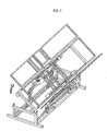
- FIG. 1 is a perspective view illustrating a structure of an adjustable bed 2 according to a first embodiment of the present invention.
- the adjustable bed 2 is constituted such that a bed frame 10 is disposed on an adjustable stage 20 placed on a fixed stage 30.
- the bed frame 10 includes a coupled platform 11a-11d, which is formed by dividing a surface part (i.e. upper surface of the bed) into four sections corresponding to the back, hip, upper-leg, and lower-leg regions of a care recipient's body lying on the bed, and coupling these sections together so as to be freely adjustable.
- a coupled platform 11a-11d an upper-body member 11a, a lower-back member 11b, an upper-leg member 11c, and a lower-leg member 11d are each coupled in the given order.
- the lower-back member 11b is fixed directly onto the adjustable stage 20 by welding, for example, thus preventing the bed frame 10 from being disengaged from the adjustable stage 20.
- Side members 12Ra-12Rd and 12La-12Ld for supporting the care recipient's body from the sides are coupled to the platform 11a-11d on the right and left, respectively.
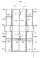
- the upper-body member 11a and upper-leg member 11c of the bed frame 10 are respectively coupled, via L-shaped couplers 211 and 212, to the shafts of direct-acting actuators M1 and M2 (see Fig. 3 showing a plan view of the bed) disposed on a center beam 21A of the adjustable stage 20.
- the actuators M1 and M2 are able to transform the bed frame 10 so that the care recipient is placed in a flexion position (see FIG. 6 showing a bed form; FIG. 8B showing a side view of the bed).
- a wire mesh is in fact placed over the surface of the coupled platform 11a-11d and side members 12Ra-12Rd and 12La-12Ld of the bed frame 10.
- this wire mesh has been omitted from the drawing as well as the following drawings in order to illustrate the structure of the bed with clarity. Consequently, these drawings depict only the frames of the coupled platform 11a-11d and side members 12Rd-12Rd and 12La-12Ld.
- the coupled platform and side members are not confined to having the wire-mesh surface construction, and may alternatively be composed of coupled pieces of a board material.
- FIGs. 5 to 7 showing bed operations certain parts of the structure, such as side-member support frames 24R and 24L, have been omitted so as to illustrate the operations with clarity.
- the side members 12Ra-12Rd/12La-12Ld the side members 12Rc/12Lc corresponding to the upper-leg region of a care recipient's body have box-shaped pockets with hollow space of approximately the same dimensions as the side members 12Rc/12Lc (see FIG. 8D showing a side view of the bed).
- Fan-shaped members 13R/13L (13R not shown) are coupled to the edges of the side members 12Rd/12Ld corresponding to the care recipient's lower-leg region. These members are normally housed in the pockets of the side members 12Rc/12Lc, respectively. Then, when the bed frame 10 is transformed into a flexion position, the fan-shaped members 13R and 13L come out of the pockets to support the care recipient's knee region.
- the adjustable stage 20 has a rectangular frame construction composed of the center beam 21A, side beams 21R and 21L, and two parallel end bars connected to either end of the center beam 21A and side beams 21R and 21L.
- rollers 200, 201, 202, and 203 are disposed so as to slide in a y direction on roller slide bars 300 of the fixed stage 30, as indicated in FIG. 1.
- Ladder-shaped side-member support frames 24R/24L are respectively disposed on the side beams 21R/21L of the adjustable stage 20.
- Each of the ladder-shaped side-member support frames 24R and 24L is composed of two bars 22R/22L and 23R/23L that run in the same direction as the side beam 21R/21L, and two connecting bars 231R/231L and 232R /232L.
- the bars 23R and 23L have concave sections in the area where the side-member support frames 24R/24L meet the side members 12Rb/12Lb, so that the side members 12Rb/12Lb fit in the space provided by the concave sections (see FIG. 3 showing a plan view of the bed).
- the adjustable stage 20 is designed in such a way that the side members 12Rb/12Lb will not interfere, in a thickness direction of the bed, with the side members 12Ra/12La and the side members 12Rc/12Lc on either side of the side members 12Rb/12Lb, when the bed frame 10 is transformed into the flexion position.
- the bars 22R/22L are coupled respectively to the side beams 21R/21L by couplers 236Ra/236La and 236Rb/236Lb, allowing the bars 22R/22L to rotate freely through an axial direction while remaining secured to the side beams 21R/21L.
- FIGs. 2A-2C are schematic sectional views of the bed showing the operation of actuators in the vicinity of the adjustable stage 20 and the upper-leg member 11c of the bed frame 10.
- direct-acting actuators M3R and M3L are symmetrically disposed on the adjustable stage 20 to the left and right of the center beam 21A (i.e. in the y direction toward the coupling members 236Ra and 236La, respectively).
- the tips of shafts of the actuators M3R/M3L are coupled to L-shaped members 235R/235L fixed directly below the rotating bars 22R/22L.
- the shafts of the actuators M3R/M3L extend, and thereby the L-shaped members 235R/235L and bars 23R/23L are rotated on the axis of the rotating bars 22R/22L. Then, the side-member support frames 24R/24L are raised from the horizontal plane to a position perpendicular to the horizontal bed surface (FIGs. 2A ⁇ 2B ⁇ 2C) .
- Stage bars 27R/27L are provided on the underside of the side beams 21R/21L, and tightly fitted into stage-bar bearings 36R/36L (U-shaped cross-sectional) located to the side of the fixed stage 30.
- stage-bar bearings 36R/36L U-shaped cross-sectional
- reverse L-shaped tabs are aligned in a width direction of the bed. These tabs hook around the stage bars 27R and 27L, and thereby the adjustable stage 20 is secured in a vertical direction.
- the stage bar i.e. either 27R or 27L
- the stage bar on the raised side is separated from the corresponding stage-bar bearing (i.e. 36R or 36L).
- FIG. 4 is a perspective view illustrating a structure of the fixed stage 30.
- the fixed stage 30 includes a rectangular frame 31. A pair of shorter ends of the frame 31 forms the roller slide bars 300 so that the rollers 200-203 of the adjustable stage 20 travel back and forth on them.
- Side beams 32R and 32L of the fixed stage 30 are slide-slot members (square-bracket cross-sectional), and are disposed such that the slide slots face one another.
- the ends of support arms 354R/354L and 356R/356L coupled respectively to the stage-bar bearings 36R/36L are tightly fitted so as to freely travel back and forth.
- Reverse L-shaped rotating arms 351R/351L and 352R/352L coupled at one end to the side beams 32R/32L are linked to the support arms 354R/354L and 356R/356L, and horizontal links 353R/353L are coupled to the rotating arms 351R/351L and 352R/352L.
- actuators M4R/M4L are respectively disposed at an angle.
- parallelogram mechanisms 35R/35L which are based on horizontal slide mechanisms, are formed on the right and left sides of the fixed stage 30.
- the rotating arms 351R/351L and 352R/352L move in a circular motion centering on the points at which they are coupled to the side beams 32R/32L.
- One ends of the support arms 354R/354L and 356R/356L travel back and forth on the inside of the side beams 32R/32L, while being regulated by the rotating arms 351R/351L and 352R/352L.
- the support arms 354R/354L and 356R/356L oscillate in a vertical direction, and thereby the adjustable stage 20, supported by the stage-bar bearings 36R and 36L, and the bed frame 10 are able to move vertically up and down from either or both the right and left sides of the fixed stage 30.
- the adjustable bed 2 can be elevated even in a small space as a consequence of space saving, while the use of the rollers 200-203 and the parallelogram mechanisms 35R and 35L realizes space saving even during postural change operations.
- a height adjustment (high/low) mechanism of the bed is realized when the parallelogram mechanisms 35R and 35L are driven simultaneously.
- actuators M1, M2, M3R, and M3L are respectively controlled by a motor driver and a CPU in a control unit (not shown). This allows the caregiver to use, for example, a controller in hand to execute drive settings such as manual/automatic setting and program setting.
- a cord-attached cable remote control or an infrared wireless remote control enables settings to be performed by the care recipient.
- Adjustable bed Postural Change from Supine to Left Lateral
- An adjustable bed having the above structure is used with a mattress placed on the bed frame 10.
- the coupled platform 11a-11d and side members 12Ra-12Rd and 12La-12Ld are set to be substantially horizontal as shown in FIG. 1.
- the actuator M3L attached to the adjustable stage 20 is operated to extend its shaft outward.
- the tips of shafts of the direct-acting actuators M1 and M2 attached to the center beam 21A of the adjustable stage 20 extend out, pushing up the upper-body member 11a and upper-leg member 11c of the bed frame 10 from the underneath via the L-shaped couplers 211 and 212 to place the care recipient in a flexion position with the upper body raised and the knees bent (FIG. 6 showing a perspective view of the bed in the flexion position; and FIGs. 8A ⁇ 8B showing side views of the bed transforming into this state).
- the side members 12La-12Ld also transform in conjunction with the coupled platform 11a-11d.
- the fun-shaped member 13L comes out from the pocket provided in the side member 12Lc to support part of the mattress and a bedding mattress around the care recipient's knee region (FIGs. 8C ⁇ 8D showing side views of the bed transforming into this state).
- the actuator M4R on the right side of the fixed stage 30 operates to extend its shaft outward.
- the stage-bar bearing 36R and the horizontal link 353R separate from one another at an angle
- the support arms 354R and 356R slide along the slide slot of the side beam 32R and rise up
- the parallelogram mechanism 35R operates.
- the support arms 354R and 356R raise the right side of the adjustable stage 20 vertically upwards as a result of the circular movement of the rotating arms 351R and 352R (or 351L and 352L) .
- a desirable tilt angle is in the range of, for example, approximately 30 degrees to 70 degrees from the horizontal, one example being a tilt angle of 50 degrees.
- the posture of the care recipient is changed smoothly from the supine to the lateral position while the body of the care recipient being supported by the coupled platform 11a-11d and the side members 12La-12Ld after firstly placed in a supine flexion position with the upper body raised and knees bent.
- Well-supported postural change that is similar to when a care recipient is turned by the guiding hand of a caregiver is thus achieved.
- postural change of the care recipient is performed in a flexion position, which imposes the least burden on the care recipient.
- the care recipient is able to comfortably take an approach to postural change.
- the caregiver is not required to perform physically hard working, manual procedures when changing the posture of the care recipient. Therefore, it is possible for even a caregiver with little experience to correctly perform postural change.
- the adjustable bed 2 of the first embodiment the caregiver is thus better able to focus on providing compassionate and attentive care.
- Adjustable Bed Mattress (having a fixture) of the Present Invention
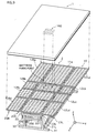
- FIG. 9 shows an exemplary structure of the adjustable bed 2 and an adjustable bed mattress used for the bed.
- the adjustable bed mattress 1 has a fixture 100 to be attached to the lower-back member 11b of the adjustable bed 2 corresponding to the hip region of a care recipient's body, as shown in FIG. 9.
- the fixture 100 has a structure in which a total of four project portions 102, each having a T-shaped cross-sectional construction, are disposed on a plate 101.
- the project portions 102 are made of hard rubber, and tightly fitted into the interstices of the wire mesh covering the surface of the lower-back member 11b of the adjustable bed 2 to fix the mattress onto the bed.
- the head and foot sides of the mattress 1 smoothly stretch while the mattress 1 is well secured around the fixture 100 as shown in FIG. 10C.
- the occurrence of displacement of the mattress 1 (in the thrust direction) due to the adjustable bed operations can be effectively prevented while a smooth mattress surface can be obtained due to the effect of the mattress stretches.
- the project portions 102 are detachable from the wire-mesh surface, which facilitates the replacement of the mattress 1 and the maintenance of the adjustable bed 2.
- the fixture 100 may be disposed on a part of the mattress 1 other than the part facing the lower-back member 11b.
- a location for setting the fixture 100 is not confined to the above, and furthermore multiple fixtures may be provided.
- the fixture is not restricted to one having the above structure, and may alternatively have another structure (e.g. use of a hook and loop fastener on a section of the platform having a flat surface) according to materials and a structure of the platform.
- the bed employs a structure that uses the parallelogram mechanisms.
- use of the adjustable bed mattress of the present invention is not limited to a bed having such a structure, and it is possible to apply the present invention also to adjustable beds having the following structures.
- An adjustable bed shown in FIG. 11A has a structure in which direct-acting actuators are disposed vertically, and a set of side members on the left or right is moved vertically up and down using a elevating mechanism.
- the platform placed on an adjustable stage is tilted.
- a pair of columnar direct-acting actuators is disposed within a rectangular fixed stage, and a bed frame supported by the adjustable stage is positioned on top of the actuators.
- the platform as in the first embodiment, is constructed as a coupled platform, which is formed by coupling together a plurality of sections corresponding to the care recipient's upper-body, hip, upper-leg, and lower-leg regions. Among these, the section corresponding to the hip region is secured to the adjustable stage having a frame construction.
- a drive unit that includes an actuator mechanism for forming a flexion position.
- the sets of side members are disposed on the columnar direct-acting actuators. Inside the side members, housing slots are formed. Here, housed in the housing slots are pullout walls, each of which formed by partitioning a panel into sections along a longitudinal direction of the bed and coupling these sections with one another.
- the side members are coupled to the adjustable stage supporting the platform via the pullout walls.
- the pullout walls are biased to a width direction of the housing slots by tension springs or the like, and are automatically housed in the housing slots when a force pulling the pullout wall out of the housing slots weakens.
- an adjustable bed having the above structure
- a flexion position is firstly formed with the coupled platform, as shown in FIG. 11B.
- one of the columnar direct-acting actuators operates to lower a set of the side members positioned thereabove.
- the adjustable stage is tilted, which brings the coupled platform down at an angle.
- the pullout wall is pulled toward the coupled platform from the corresponding housing slot in a manner that the pullout wall is raised relative to the coupled platform. That is, the pullout wall at the lower side hangs from the coupled platform with the angle between the two narrowed.
- the side members are placed in a raised state relative to the coupled platform. This achieves the effect of supporting the side of the care recipient's body with the pullout wall while keeping the care recipient in the flexion position.
- postural change is performed in a favorable manner, as in the first embodiment.
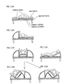
- FIGs. 12A-12F illustrate a structure of another adjustable bed.
- the structure of this adjustable bed can be adopted by general-purpose beds.
- the adjustable bed is constituted by laying an air mattress formed from a plurality of airbags on a general-purpose bed.
- a characteristic of this adjustable bed is the use of an air pump to supply/discharge air independently for each airbag via an air hose.
- the air hose has a valve whose opening/closing motions, along with the air pump, are controlled by a control unit (not depicted), and thus, the inflation/deflation of respective airbags are individually controlled.
- the airbags are, as one example, partitioned into an upper body and hip portion (double layer), an upper and lower leg portion, and portions for right and left sides of the bed according to the joints of a care recipient's body.
- An adjustable bed having the above structure is normally used with a bedding mattress or the like placed over the air mattress.
- the airbags on both sides of the bed are firstly inflated (FIGs. 12A ⁇ 12B).
- the care recipient is placed in a flexion position by tilting the airbag of upper body and hip portion in a longitudinal direction, and inflating the airbag of upper and lower leg portion so as to form a knee break (FIGs. 12C and 12D).
- the adjustable bed having the above structure has an advantage in portability, and therefore the bed can, in addition to being applied to a variety of general-purpose beds, also be laid directly on the floor (i.e. directly over tatami mats, carpet, or the like).
- An adjustable bed mattress according to the present invention can be used as a mattress used for a nursing care bed or a reclining bed.
Landscapes
- Health & Medical Sciences (AREA)
- Nursing (AREA)
- Life Sciences & Earth Sciences (AREA)
- Animal Behavior & Ethology (AREA)
- General Health & Medical Sciences (AREA)
- Public Health (AREA)
- Veterinary Medicine (AREA)
- Invalid Beds And Related Equipment (AREA)
- Mattresses And Other Support Structures For Chairs And Beds (AREA)
Applications Claiming Priority (3)
| Application Number | Priority Date | Filing Date | Title |
|---|---|---|---|
| JP2002241044 | 2002-08-21 | ||
| JP2002241044A JP3960885B2 (ja) | 2002-08-21 | 2002-08-21 | 可動ベッド用マット |
| PCT/JP2003/010544 WO2004032814A1 (ja) | 2002-08-21 | 2003-08-21 | 可動ベッド用マット |
Publications (2)
| Publication Number | Publication Date |
|---|---|
| EP1541109A1 true EP1541109A1 (de) | 2005-06-15 |
| EP1541109A4 EP1541109A4 (de) | 2008-08-13 |
Family
ID=32023653
Family Applications (1)
| Application Number | Title | Priority Date | Filing Date |
|---|---|---|---|
| EP03807959A Withdrawn EP1541109A4 (de) | 2002-08-21 | 2003-08-21 | Matratze für ein bewegliches bett |
Country Status (6)
| Country | Link |
|---|---|
| US (1) | US20060117479A1 (de) |
| EP (1) | EP1541109A4 (de) |
| JP (1) | JP3960885B2 (de) |
| KR (1) | KR20050058345A (de) |
| TW (1) | TWI260218B (de) |
| WO (1) | WO2004032814A1 (de) |
Cited By (6)
| Publication number | Priority date | Publication date | Assignee | Title |
|---|---|---|---|---|
| WO2007054683A3 (en) * | 2005-11-14 | 2007-08-02 | Huntleigh Technology Plc | Actuator support system |
| NL1035102C2 (nl) * | 2008-02-28 | 2009-08-31 | Neggers Johannes Cornelis Mari | Inrichting voor aanpassing van de vorm van een steunvlak. |
| WO2009120064A2 (en) | 2008-03-28 | 2009-10-01 | Neggers Johannes Cornelis Mari | Assembly for adapting a support surface in a wave shape |
| WO2011071777A1 (en) * | 2009-12-07 | 2011-06-16 | Dreamwell, Ltd. | Shell for mattress for adjustable bed |
| EP2932951A1 (de) * | 2014-04-15 | 2015-10-21 | Panasonic Intellectual Property Management Co., Ltd. | Integrierte bettmatratze und integriertes bett |
| US12527706B2 (en) | 2022-03-14 | 2026-01-20 | Stryker Corporation | Patient support apparatus with mattress and mattress coupler |
Families Citing this family (27)
| Publication number | Priority date | Publication date | Assignee | Title |
|---|---|---|---|---|
| KR100621350B1 (ko) * | 2006-05-12 | 2006-09-07 | 주식회사 해피베드 | 하지 관절 운동이 가능한 작동구조를 갖는 환자용 침대 |
| KR100621349B1 (ko) | 2006-05-12 | 2006-09-07 | 주식회사 해피베드 | 분할된 등받이부의 각도 조절이 가능한 환자용 침대 |
| KR100661870B1 (ko) | 2006-05-12 | 2006-12-27 | 주식회사 해피베드 | 밀림방지구조를 갖는 각도 조절식 환자용 침대 |
| US8739333B2 (en) * | 2010-04-05 | 2014-06-03 | Central City Concern | Bedbug infestation-resistant bed |
| EP2581072B1 (de) * | 2010-06-08 | 2017-11-08 | Panasonic Intellectual Property Management Co., Ltd. | Bett, verfahren zum zusammenbau des bettes und verfahren zur demontage des bettes |
| JP5138081B1 (ja) * | 2011-09-13 | 2013-02-06 | 株式会社プラッツ | マットレス |
| US9173796B2 (en) | 2013-02-05 | 2015-11-03 | Hill-Rom Services, Inc. | Bed with a powered width expansion wing with manual release |
| JP6114094B2 (ja) * | 2013-04-15 | 2017-04-12 | パラマウントベッド株式会社 | ベッド装置 |
| EP2987475A4 (de) * | 2013-04-18 | 2016-11-16 | Paramount Bed Kk | Boden für eine bettvorrichtung |
| JP5876617B2 (ja) * | 2013-05-13 | 2016-03-02 | パラマウントベッド株式会社 | ベッド装置 |
| US10188569B2 (en) | 2013-09-06 | 2019-01-29 | Stryker Corporation | Patient support usable with bariatric patients |
| CA3129202C (en) | 2013-09-06 | 2023-12-19 | Stryker Corporation | Patient support usable with bariatric patients |
| US20150208813A1 (en) * | 2014-01-24 | 2015-07-30 | L & P Property Management Company | Mattress-retention decking |
| US11224294B2 (en) * | 2015-06-19 | 2022-01-18 | Tempur World, Llc | Adjustable base assemblies, systems and related methods |
| GB2542584B (en) * | 2015-09-23 | 2019-12-11 | Ferno Uk Ltd | Stretcher arrangement |
| JP5982662B1 (ja) * | 2015-10-06 | 2016-08-31 | 林金属工業株式会社 | 介護用ベッド |
| JP6274549B1 (ja) * | 2016-04-28 | 2018-02-07 | 株式会社工房利匠 | 寝台 |
| US11304864B2 (en) * | 2016-09-02 | 2022-04-19 | Stryker Corporation | Patient support systems with a chair configuration and a stowable foot section |
| US10842701B2 (en) | 2016-10-14 | 2020-11-24 | Stryker Corporation | Patient support apparatus with stabilization |
| FR3069153B1 (fr) * | 2017-07-18 | 2021-12-24 | Guy Wackermann | Support de lit |
| JP6450441B1 (ja) * | 2017-11-28 | 2019-01-09 | 和男 川本 | 介護用椅子 |
| TWM559120U (zh) * | 2018-02-01 | 2018-05-01 | Ulife Healthcare Inc | 電動傢俱床 |
| CN108937330B (zh) * | 2018-08-03 | 2021-09-07 | 浙江想能睡眠科技股份有限公司 | 一种实现倾斜度调节的软硬可调床体及其智能控制方法 |
| US11684530B2 (en) | 2019-04-12 | 2023-06-27 | Hill-Rom Services, Inc. | Mattress retention assembly and radiofrequency weld in surface covers |
| US10888171B1 (en) * | 2019-07-29 | 2021-01-12 | Gary Kinion | Tilt bed tiltable extension |
| CN112107437A (zh) * | 2020-08-10 | 2020-12-22 | 河北万瑞医疗器械有限公司 | 一种止鼾医疗床 |
| CN114631945B (zh) * | 2022-03-10 | 2023-03-31 | 南通大学附属医院 | 一种基于大数据的心内科介入术后肢体护理装置 |
Family Cites Families (27)
| Publication number | Priority date | Publication date | Assignee | Title |
|---|---|---|---|---|
| US1842873A (en) * | 1930-07-29 | 1932-01-26 | Mary E Leeking | Mattress holder |
| US2588854A (en) * | 1946-12-11 | 1952-03-11 | Helen E Lang | Mattress holder |
| US2634426A (en) * | 1950-02-24 | 1953-04-14 | Anna S Anderson | Mattress |
| US3905053A (en) * | 1974-08-05 | 1975-09-16 | Mario Vuchelich | Convertible bed sofa |
| JPS5419118Y2 (de) * | 1975-04-09 | 1979-07-16 | ||
| JPH0653087B2 (ja) * | 1981-04-10 | 1994-07-20 | 忠 井浦 | 傾動型ベッド |
| US4899404A (en) * | 1985-11-25 | 1990-02-13 | Galumbeck Michael H | Elevation system for a bed assembly |
| CN1033360C (zh) * | 1992-08-30 | 1996-11-27 | 陈海就 | 万向滚动按摩磁疗褥垫 |
| JPH0731642A (ja) * | 1993-07-16 | 1995-02-03 | Aisin Seiki Co Ltd | ベッド |
| US5491854A (en) * | 1994-05-19 | 1996-02-20 | Music; Earl D. | Inflatable mattress and bed assembly with taut, tensioned cover |
| JP3182043B2 (ja) * | 1994-06-21 | 2001-07-03 | アップリカ▲葛▼西株式会社 | ベッド |
| JP2910589B2 (ja) * | 1994-11-21 | 1999-06-23 | トミ 三野 | ベッド |
| JPH08308885A (ja) * | 1995-05-18 | 1996-11-26 | Takashi Sakai | 起き上がりベッド装置 |
| US5682631A (en) * | 1995-08-04 | 1997-11-04 | Hill-Rom, Inc. | Bed having a reduced-shear pivot and step deck combination |
| US6012186A (en) * | 1997-04-29 | 2000-01-11 | Hill-Rom Compnay, Inc. | Mattress articulation structure |
| JP2000139657A (ja) * | 1998-11-10 | 2000-05-23 | Tsunayoshi Morikawa | ベッドマットレス用シーツ |
| JP2001008979A (ja) * | 1999-06-29 | 2001-01-16 | Kanayama Kosan Kk | 介護用ベッド及び介護用ベッドのマットレス |
| JP2001161505A (ja) * | 1999-12-08 | 2001-06-19 | Otsuka Chem Co Ltd | マットレス芯及びマットレス |
| JP2001258952A (ja) * | 2000-03-14 | 2001-09-25 | Matsushita Electric Works Ltd | 介護ベッド |
| JP2001293037A (ja) * | 2000-04-13 | 2001-10-23 | Fukuju Sangyo Kk | 可動ベッド |
| JP2001299825A (ja) * | 2000-04-24 | 2001-10-30 | Yoshihiko Takeshima | 横転自在マット装置 |
| JP3712600B2 (ja) * | 2000-09-11 | 2005-11-02 | 株式会社ライジング・セブン | ベッド |
| JP2002119388A (ja) * | 2000-10-13 | 2002-04-23 | Symbolic Atorii:Kk | マットレス |
| JP2003310668A (ja) * | 2002-02-22 | 2003-11-05 | Sanyo Electric Co Ltd | 可動ベッド |
| WO2004026211A1 (ja) * | 2002-08-29 | 2004-04-01 | Sanyo Electric Co., Ltd. | 可動ベッド |
| JP3957597B2 (ja) * | 2002-09-04 | 2007-08-15 | 三洋電機株式会社 | 可動ベッド |
| JP2004121837A (ja) * | 2002-09-11 | 2004-04-22 | Sanyo Electric Co Ltd | 可動ベッド |
-
2002
- 2002-08-21 JP JP2002241044A patent/JP3960885B2/ja not_active Expired - Fee Related
-
2003
- 2003-08-21 WO PCT/JP2003/010544 patent/WO2004032814A1/ja not_active Ceased
- 2003-08-21 TW TW092122962A patent/TWI260218B/zh not_active IP Right Cessation
- 2003-08-21 EP EP03807959A patent/EP1541109A4/de not_active Withdrawn
- 2003-08-21 KR KR1020057002727A patent/KR20050058345A/ko not_active Withdrawn
- 2003-08-21 US US10/524,736 patent/US20060117479A1/en not_active Abandoned
Cited By (8)
| Publication number | Priority date | Publication date | Assignee | Title |
|---|---|---|---|---|
| WO2007054683A3 (en) * | 2005-11-14 | 2007-08-02 | Huntleigh Technology Plc | Actuator support system |
| NL1035102C2 (nl) * | 2008-02-28 | 2009-08-31 | Neggers Johannes Cornelis Mari | Inrichting voor aanpassing van de vorm van een steunvlak. |
| WO2009120064A2 (en) | 2008-03-28 | 2009-10-01 | Neggers Johannes Cornelis Mari | Assembly for adapting a support surface in a wave shape |
| WO2011071777A1 (en) * | 2009-12-07 | 2011-06-16 | Dreamwell, Ltd. | Shell for mattress for adjustable bed |
| US9301622B2 (en) | 2009-12-07 | 2016-04-05 | Dreamwell, Ltd. | Shell for mattress for adjustable bed |
| EP2932951A1 (de) * | 2014-04-15 | 2015-10-21 | Panasonic Intellectual Property Management Co., Ltd. | Integrierte bettmatratze und integriertes bett |
| US9757287B2 (en) | 2014-04-15 | 2017-09-12 | Panasonic Intellectual Property Management Co., Ltd. | Integrated-bed mattress and integrated bed |
| US12527706B2 (en) | 2022-03-14 | 2026-01-20 | Stryker Corporation | Patient support apparatus with mattress and mattress coupler |
Also Published As
| Publication number | Publication date |
|---|---|
| KR20050058345A (ko) | 2005-06-16 |
| US20060117479A1 (en) | 2006-06-08 |
| WO2004032814A1 (ja) | 2004-04-22 |
| JP3960885B2 (ja) | 2007-08-15 |
| TW200407105A (en) | 2004-05-16 |
| JP2004073673A (ja) | 2004-03-11 |
| EP1541109A4 (de) | 2008-08-13 |
| TWI260218B (en) | 2006-08-21 |
Similar Documents
| Publication | Publication Date | Title |
|---|---|---|
| US20060117479A1 (en) | Mattress for movable bed | |
| US7246389B2 (en) | Adjustable bed | |
| US7730562B2 (en) | Patient support having powered adjustable width | |
| US7165277B2 (en) | Adjustable bed | |
| US12377004B2 (en) | Patient support systems with a chair configuration and a stowable foot section | |
| US7712168B2 (en) | Articulating bed and method of using the same | |
| KR101630381B1 (ko) | 리프트를 구비한 욕창방지용 침대 | |
| EP1541108A1 (de) | Bewegliches bett | |
| KR101227967B1 (ko) | 의료용 욕창방지 침대 | |
| JP2022000230A (ja) | ベッド装置 | |
| US20060016016A1 (en) | Modular bed system | |
| KR102081700B1 (ko) | 조립식 전동침대 | |
| JP3712600B2 (ja) | ベッド | |
| US10959534B2 (en) | Oblique hinged panels and bladder apparatus for sleep disorders | |
| JP2002035052A (ja) | 介助用マット装置 | |
| JP7127011B2 (ja) | マットレスおよびベッド装置 | |
| KR101846127B1 (ko) | 자유롭게 변형 가능한 침대 | |
| JPH09131380A (ja) | 床ずれ防止ベッド | |
| JP3568738B2 (ja) | ベッド装置 | |
| JP3562937B2 (ja) | ベッド装置 | |
| JPH11221136A (ja) | 起き上がり装置 | |
| JP2004166987A (ja) | 介護用ベッド | |
| JP2001269371A (ja) | ベッド |
Legal Events
| Date | Code | Title | Description |
|---|---|---|---|
| PUAI | Public reference made under article 153(3) epc to a published international application that has entered the european phase |
Free format text: ORIGINAL CODE: 0009012 |
|
| 17P | Request for examination filed |
Effective date: 20050318 |
|
| AK | Designated contracting states |
Kind code of ref document: A1 Designated state(s): AT BE BG CH CY CZ DE DK EE ES FI FR GB GR HU IE IT LI LU MC NL PT RO SE SI SK TR |
|
| RBV | Designated contracting states (corrected) |
Designated state(s): DE ES GB |
|
| A4 | Supplementary search report drawn up and despatched |
Effective date: 20080716 |
|
| STAA | Information on the status of an ep patent application or granted ep patent |
Free format text: STATUS: THE APPLICATION IS DEEMED TO BE WITHDRAWN |
|
| 18D | Application deemed to be withdrawn |
Effective date: 20081015 |