EP1541417B1 - Fahrweg Anzeigesystem für ein Fahrzeug mit Randanzeigemarkierung für den Fahrwegsbereich - Google Patents
Fahrweg Anzeigesystem für ein Fahrzeug mit Randanzeigemarkierung für den Fahrwegsbereich Download PDFInfo
- Publication number
- EP1541417B1 EP1541417B1 EP04078316A EP04078316A EP1541417B1 EP 1541417 B1 EP1541417 B1 EP 1541417B1 EP 04078316 A EP04078316 A EP 04078316A EP 04078316 A EP04078316 A EP 04078316A EP 1541417 B1 EP1541417 B1 EP 1541417B1
- Authority
- EP
- European Patent Office
- Prior art keywords
- reticle
- path
- conical
- view
- vehicle
- Prior art date
- Legal status (The legal status is an assumption and is not a legal conclusion. Google has not performed a legal analysis and makes no representation as to the accuracy of the status listed.)
- Expired - Lifetime
Links
- 230000037361 pathway Effects 0.000 title abstract description 9
- 230000002238 attenuated effect Effects 0.000 claims abstract description 11
- 239000000758 substrate Substances 0.000 claims description 10
- 238000003384 imaging method Methods 0.000 claims 1
- 238000000151 deposition Methods 0.000 description 3
- 239000011521 glass Substances 0.000 description 3
- 230000008021 deposition Effects 0.000 description 2
- 238000010586 diagram Methods 0.000 description 2
- 239000000463 material Substances 0.000 description 2
- 230000003287 optical effect Effects 0.000 description 2
- VYZAMTAEIAYCRO-UHFFFAOYSA-N Chromium Chemical compound [Cr] VYZAMTAEIAYCRO-UHFFFAOYSA-N 0.000 description 1
- XAGFODPZIPBFFR-UHFFFAOYSA-N aluminium Chemical compound [Al] XAGFODPZIPBFFR-UHFFFAOYSA-N 0.000 description 1
- 229910052782 aluminium Inorganic materials 0.000 description 1
- 239000004411 aluminium Substances 0.000 description 1
- 230000005540 biological transmission Effects 0.000 description 1
- 229910052804 chromium Inorganic materials 0.000 description 1
- 239000011651 chromium Substances 0.000 description 1
- 238000001514 detection method Methods 0.000 description 1
- 238000005530 etching Methods 0.000 description 1
Images

Classifications
-
- B—PERFORMING OPERATIONS; TRANSPORTING
- B60—VEHICLES IN GENERAL
- B60R—VEHICLES, VEHICLE FITTINGS, OR VEHICLE PARTS, NOT OTHERWISE PROVIDED FOR
- B60R1/00—Optical viewing arrangements; Real-time viewing arrangements for drivers or passengers using optical image capturing systems, e.g. cameras or video systems specially adapted for use in or on vehicles
- B60R1/20—Real-time viewing arrangements for drivers or passengers using optical image capturing systems, e.g. cameras or video systems specially adapted for use in or on vehicles
- B60R1/22—Real-time viewing arrangements for drivers or passengers using optical image capturing systems, e.g. cameras or video systems specially adapted for use in or on vehicles for viewing an area outside the vehicle, e.g. the exterior of the vehicle
- B60R1/23—Real-time viewing arrangements for drivers or passengers using optical image capturing systems, e.g. cameras or video systems specially adapted for use in or on vehicles for viewing an area outside the vehicle, e.g. the exterior of the vehicle with a predetermined field of view
- B60R1/26—Real-time viewing arrangements for drivers or passengers using optical image capturing systems, e.g. cameras or video systems specially adapted for use in or on vehicles for viewing an area outside the vehicle, e.g. the exterior of the vehicle with a predetermined field of view to the rear of the vehicle
-
- G—PHYSICS
- G01—MEASURING; TESTING
- G01C—MEASURING DISTANCES, LEVELS OR BEARINGS; SURVEYING; NAVIGATION; GYROSCOPIC INSTRUMENTS; PHOTOGRAMMETRY OR VIDEOGRAMMETRY
- G01C3/00—Measuring distances in line of sight; Optical rangefinders
- G01C3/22—Measuring distances in line of sight; Optical rangefinders using a parallactic triangle with variable angles and a base of fixed length at, near, or formed by the object
-
- B—PERFORMING OPERATIONS; TRANSPORTING
- B60—VEHICLES IN GENERAL
- B60R—VEHICLES, VEHICLE FITTINGS, OR VEHICLE PARTS, NOT OTHERWISE PROVIDED FOR
- B60R2300/00—Details of viewing arrangements using cameras and displays, specially adapted for use in a vehicle
- B60R2300/30—Details of viewing arrangements using cameras and displays, specially adapted for use in a vehicle characterised by the type of image processing
- B60R2300/304—Details of viewing arrangements using cameras and displays, specially adapted for use in a vehicle characterised by the type of image processing using merged images, e.g. merging camera image with stored images
- B60R2300/305—Details of viewing arrangements using cameras and displays, specially adapted for use in a vehicle characterised by the type of image processing using merged images, e.g. merging camera image with stored images merging camera image with lines or icons
Definitions
- the present invention relates to a pathway vision system for a vehicle, and more particularly to a system that visually distinguishes between in-path and out-of-path regions of a displayed view.
- Vehicle pathway vision systems use one or more video cameras to display video images in the direction of the forward or reverse pathway of the vehicle to help the driver manoeuvre the vehicle in a safe manner.
- the displayed image can be used for vision enhancement during poor lighting conditions, or to present a view that is otherwise restricted or hidden.
- a reverse pathway image can be displayed as a back-up aid. While it is generally desirable to display a wide field-of-view (FOV) that includes both in-path and out-of-path objects, the driver may have difficulty determining whether a displayed object is in-path or out-of path, and how far the object is from the vehicle.
- FOV field-of-view
- an apparatus for displaying a video image of a scene in travel paths of a vehicle in accordance with claim 1.
- the present invention is directed to vehicle vision system for displaying an image of a scene in the direction of the vehicle pathway, where the displayed image includes a reticle that visually delineates the in-path portion of the scene.
- the reticle is preferably formed by a reticle array disposed between a video camera chip and a lens, the array including a conical or frustroconical region of substantially an-unattenuated light transmissivity surrounded by a region of perceptibly attenuated light transmissivity, such that in-path portions of the displayed image are substantially without attenuation and out-of-path
- the reticle array 32 can be designed so that the out-of-path display region 14b appears lighter than the in-path region 14a, instead of darker; this can be achieved by side-lighting of the substrate 30, for example.
- the reticle of this invention provides the driver a convenient vehicle-based frame of reference for easily and reliably distinguishing between in-path and out-of-path objects when the reticle includes one or more stadia lines 32c. portions of the displayed image are perceptibly attenuated. As a result, the driver can easily and reliably distinguish between in-path and out-of-path objects in the displayed scene.
- the reticle array preferably also includes a number of reduced transmissivity or opaque lines traversing its conical or frustro-conical region to produce a series of receding stadia lines in the in-path portion of the displayed image, enabling the driver to reliably discern the range of displayed objects.
- the vision system of the present invention is disclosed in the context of a back-up aid for a motor vehicle, where the driver views a video image of a scene along the rearward travel path of the vehicle to determine if the travel path is obstructed.
- the system may be part of a more sophisticated control such as a driver warning control or a collision avoidance control.
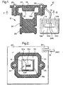
- the vision system is generally designated by the reference numeral 10, and fundamentally includes a camera assembly 12 and a display device 14 (such as a conventional flat-panel display) coupled to the camera assembly 12 by a video cable 16.
- the camera assembly 12 may be mounted, for example, in a central rearward portion of the vehicle, such as in the vicinity of a center-high-mounted-stop-lamp (CHMSL) or the like, whereas the display device 14 will typically be mounted in the vehicle instrument panel or in the vicinity of an interior rear-view mirror.
- CHMSL center-high-mounted-stop-lamp
- the camera assembly 12 essentially comprises a video camera chip 18 and an optical lens 20.
- the camera chip 18 is mounted on a printed circuit board 22, and the lens 20 is fixed in a lens holder 24 that is secured to the circuit board 22 by a set of fasteners 26.
- the circuit board 22 will typically support other circuit elements such as a video processing chip, and the video output for display device 14 is coupled to video cable 16 via a suitable circuit board connector 28.
- the lens 20 typically comprises a collection of optical elements designed to gather light from a specified field-of-view (FOV) and to focus the light on a focal plane at or near the surface of the camera chip 18.
- FOV field-of-view
- a relatively wide field-of-view is usually specified, such as 110° in azimuth and 85° in elevation, so as to present sufficient information to enable the driver to determine if it is safe to proceed.
- the displayed image necessarily encompasses both in-path and out-of-path objects, as well as objects at different distances from the rear of the vehicle.
- the exposed or outboard surface of camera chip 18 is protected by an integral glass cover 18a, and a reticle substrate 30 is adhered to the glass cover 18a.
- the reticle substrate 30 is preferably formed of optically transparent glass, processed to define a central reticle array 32 that is aligned with the photo-sensitive cells of camera chip 18.
- Light impinging on the camera chip 18 first passes through the reticle array 32 so that the features of reticle array 32 appear on display device 14, superimposed on the displayed rearward scene substantially as shown in Figure 1.
- the reticle 32 array defines a conical or frustro-conical region 32a of substantially un-attenuated light transmissivity surrounded by a region 32b of perceptibly attenuated light transmissivity.
- the region 32a represents the portion of the displayed scene through which the vehicle will travel, and thus contains objects that are considered to be in-path.
- the region 32b includes the remainder of the displayed scene, and thus contains objects that are considered to be out-of-path.
- in-path portions of the displayed image are optically un-attenuated
- out-of-path portions of the displayed image while still visible, are perceptibly attenuated.
- the driver can easily and reliably distinguish between in-path and out-of-path objects; those objects within the display region 14a are in-path, and those objects within the display region 14b are out-of-path.
- the reticle array 32 may be configured so that the width of the region 14a is somewhat larger than the vehicle width to compensate for slight errors in driver judgment.
- the reticle array 32 preferably also includes a number of reduced transmissivity lines 32c traversing its conical or frustro-conical region 32a to produce a series of receding stadia lines 34a, 34b, 34c in the in-path region 14a of the displayed image.
- the stadia lines 34a, 34b, 34c appear to be located at different distances from the vehicle due to their length and position within the display region 14a, and provide the driver one or more reference marks for determining the distance between the vehicle and objects appearing on display device 14.
- the stadia lines 34a, 34b, 34c may be placed so they appear to be lying at distances of one, two and three meters from the vehicle.
- the driver can conclude that the object is approximately two meters from the rear of the vehicle, and so on. If the width of the in-path region is somewhat wider than the vehicle width as mentioned above, the stadia lines may be somewhat narrower in length as shown in Figure 1 to represent the vehicle width, if desired.
- the reticle array 32 is preferably defined by a pattern of lines formed on the substrate 30.
- the dense pattern of parallel lines in the out-of-path region 32b perceptibly attenuate light transmission, and at the same time define the bounds of the in-path region 32a.
- the shape of the in-path region 32a may be conical or frustro-conical as shown.
- the parallel lines in the out-of-path region 32b may be formed by physically marring or etching the substrate 30, or by depositing a thin layer of material on the substrate 30.
- Deposition materials have absorptive and/or reflective properties that vary with the deposition thickness, and may include aluminium or chromium, for example.
- the stadia lines 32c on the other hand, must be individually visible in the displayed image, and are therefore much wider and more opaque than the parallel lines defining the out-of-path region 32b.
Landscapes
- Engineering & Computer Science (AREA)
- Physics & Mathematics (AREA)
- Multimedia (AREA)
- General Physics & Mathematics (AREA)
- Radar, Positioning & Navigation (AREA)
- Remote Sensing (AREA)
- Electromagnetism (AREA)
- Mechanical Engineering (AREA)
- Closed-Circuit Television Systems (AREA)
- Studio Devices (AREA)
- Fittings On The Vehicle Exterior For Carrying Loads, And Devices For Holding Or Mounting Articles (AREA)
- Control Of Position, Course, Altitude, Or Attitude Of Moving Bodies (AREA)
- Traffic Control Systems (AREA)
Claims (9)
- Vorrichtung zum Anzeigen eines Videobildes einer Szene in einem Fahrweg eines Fahrzeugs, welche umfasst:eine Videokameraeinrichtung (18) und eine Linse (20) zum Abbilden eines Sichtfeldes, das den Fahrweg einschließt, wobei das Sichtfeld sowohl Nicht-Fahrweg-Objekte, die sich außerhalb des Fahrwegs befinden, als auch Fahrweg-Objekte, die sich innerhalb des Fahrwegs befinden, einschließt;eine Videoanzeigeeinrichtung (14) zum Anzeigen des abgebildeten Sichtfeldes; und ein Mittel zum Bereitstellen einer Markierung (14a, 14b) auf der Videoanzeigeeinrichtung (14) zum sichtbaren Abgrenzen eines Fahrweg-Teilbereichs des Sichtfeldes, in dem die Fahrweg-Objekte angezeigt werden, von einem Nicht-Fahrweg-Teilbereich des Sichtfeldes, in dem die Nicht-Fahrweg-Objekte angezeigt werden;dadurch gekennzeichnet, dass das Mittel zum Bereitstellen einer Markierung umfasst:ein Markierungssubstrat (30), das zwischen der Videokameraeinrichtung (18) und der Linse (20) angeordnet ist; undeine Markierungsanordnung (32), die auf dem Markierungssubstrat (30) ausgebildet ist, so dass das abgebildete und angezeigte Sichtfeld ein Bild der Markierungsanordnung (32) aufweist, wobei die Markierung (14a, 14b) durch ein derartiges Bild einer derartigen Markierungsanordnung (32) definiert ist.
- Vorrichtung nach Anspruch 1, wobei der abgegrenzte Fahrweg-Teilbereich des angezeigten Sichtfeldes (14a) kegelförmig oder kegelstumpfförmig ist.
- Vorrichtung nach Anspruch 1, wobei der abgegrenzte Fahrweg-Teilbereich des angezeigten Sichtfeldes (14a) kegelförmig oder kegelstumpfförmig ist und die Markierung eine oder mehrere Distanzstriche (34a bis 34c) aufweist, welche durch den Fahrweg-Teilbereich (14a) hindurchgehen, um bei einer Schätzung einer Entfernung eines Objekts von dem Fahrzeug zu helfen.
- Vorrichtung nach Anspruch 3, wobei die Distanzstriche (34a - 34c) eine Länge aufweisen, die einer Breite des Fahrzeugs entspricht.
- Vorrichtung nach Anspruch 4, wobei der abgegrenzte Fahrweg-Teilbereich des angezeigten Sichtfeldes (14a) breiter als eine Länge der Distanzstriche (34a - 34c) ist.
- Vorrichtung nach Anspruch 3, die eine Reihe von sukzessiv zurückgehenden Distanzstrichen (34a - 34c) in dem abgegrenzten Fahrweg-Teilbereich des angezeigten Sichtfeldes (14a) aufweist, welche sukzessiv weiteren Entfernungen von dem Fahrzeug entsprechen.
- Vorrichtung nach Anspruch 1, wobei:das Markierungssubstrat (30) optisch transparent ist; unddie Markierungsanordnung (32) einen kegelförmigen oder kegelstumpfförmigen Bereich mit im Wesentlichen nicht abgeschwächtem Lichttransmissionsgrad (32a), der dem Fahrweg-Teilbereich des angezeigten Sichtfeldes (14a) entspricht, und einen Bereich mit erkennbar abgeschwächtem Lichttransmissionsgrad (32b) aufweist, der dem Nicht-Fahrweg-Teilbereich des angezeigten Sichtfeldes (14b) entspricht.
- Vorrichtung nach Anspruch 1, wobei:die Markierungsanordnung (32) einen kegelförmigen oder kegelstumpfförmigen Bereich (32a) definiert, welcher dem Fahrweg-Teilbereich des angezeigten Sichtfeldes (14a) entspricht, und eine oder mehrere Distanzstriche (32c) aufweist, welche durch den kegelförmigen oder kegelstumpfförmigen Bereich (32a) hindurchgehen, um bei einer Schätzung einer Entfernung eines Objekts von dem Fahrzeug zu helfen.
- Vorrichtung nach Anspruch 1, wobei das Markierungssubstrat eine Abdeckung (18a) der Videokameraeinrichtung ist.
Applications Claiming Priority (2)
| Application Number | Priority Date | Filing Date | Title |
|---|---|---|---|
| US10/734,317 US7423665B2 (en) | 2003-12-12 | 2003-12-12 | Vehicle pathway vision system having in-path delineation reticle |
| US734317 | 2003-12-12 |
Publications (2)
| Publication Number | Publication Date |
|---|---|
| EP1541417A1 EP1541417A1 (de) | 2005-06-15 |
| EP1541417B1 true EP1541417B1 (de) | 2007-02-21 |
Family
ID=34523083
Family Applications (1)
| Application Number | Title | Priority Date | Filing Date |
|---|---|---|---|
| EP04078316A Expired - Lifetime EP1541417B1 (de) | 2003-12-12 | 2004-12-07 | Fahrweg Anzeigesystem für ein Fahrzeug mit Randanzeigemarkierung für den Fahrwegsbereich |
Country Status (4)
| Country | Link |
|---|---|
| US (1) | US7423665B2 (de) |
| EP (1) | EP1541417B1 (de) |
| AT (1) | ATE354498T1 (de) |
| DE (1) | DE602004004859T2 (de) |
Families Citing this family (21)
| Publication number | Priority date | Publication date | Assignee | Title |
|---|---|---|---|---|
| AU2003290791A1 (en) | 2002-11-14 | 2004-06-15 | Donnelly Corporation | Imaging system for vehicle |
| WO2007053404A2 (en) * | 2005-10-28 | 2007-05-10 | Donnelly Corporation | Camera module for vehicle vision system |
| US8482664B2 (en) | 2008-10-16 | 2013-07-09 | Magna Electronics Inc. | Compact camera and cable system for vehicular applications |
| US8866907B2 (en) | 2009-02-06 | 2014-10-21 | Magna Electronics Inc. | Camera for mounting on a vehicle |
| US12328491B1 (en) | 2009-03-25 | 2025-06-10 | Magna Electronics Inc. | Vehicular camera and lens assembly |
| US8542451B2 (en) | 2009-03-25 | 2013-09-24 | Magna Electronics Inc. | Vehicular camera and lens assembly |
| US9380219B2 (en) | 2011-04-20 | 2016-06-28 | Magna Electronics Inc. | Angular filter for vehicle mounted cameras |
| US9871971B2 (en) | 2011-08-02 | 2018-01-16 | Magma Electronics Inc. | Vehicle vision system with light baffling system |
| WO2013019795A1 (en) | 2011-08-02 | 2013-02-07 | Magna Electronics Inc. | Vehicular camera system |
| US9451138B2 (en) | 2013-11-07 | 2016-09-20 | Magna Electronics Inc. | Camera for vehicle vision system |
| KR102213657B1 (ko) * | 2014-01-28 | 2021-02-08 | 엘지이노텍 주식회사 | 카메라 모듈 |
| US9749509B2 (en) | 2014-03-13 | 2017-08-29 | Magna Electronics Inc. | Camera with lens for vehicle vision system |
| TWM492262U (zh) * | 2014-07-18 | 2014-12-21 | Seeways Technology Inc | 自動顯示三態視角之倒車顯影系統及其倒車攝影裝置 |
| US9955054B2 (en) | 2015-02-05 | 2018-04-24 | Robert Bosch Gmbh | Camera and method for assembling with fixed final alignment |
| US10250004B2 (en) | 2015-11-05 | 2019-04-02 | Magna Electronics Inc. | Method of forming a connector for an electrical cable for electrically connecting to a camera of a vehicle |
| US10351072B2 (en) | 2015-11-05 | 2019-07-16 | Magna Electronics Inc. | Vehicle camera with modular construction |
| US10560613B2 (en) | 2015-11-05 | 2020-02-11 | Magna Electronics Inc. | Vehicle camera with modular construction |
| US10230875B2 (en) | 2016-04-14 | 2019-03-12 | Magna Electronics Inc. | Camera for vehicle vision system |
| US10142532B2 (en) | 2016-04-08 | 2018-11-27 | Magna Electronics Inc. | Camera for vehicle vision system |
| US10237456B2 (en) | 2016-08-22 | 2019-03-19 | Magna Electronics Inc. | Vehicle camera assembly process |
| JP2018059986A (ja) * | 2016-10-03 | 2018-04-12 | 株式会社デンソー | 撮像装置 |
Family Cites Families (10)
| Publication number | Priority date | Publication date | Assignee | Title |
|---|---|---|---|---|
| US3434214A (en) | 1965-10-20 | 1969-03-25 | James S Pratt | Measuring device for safety distances between moving vehicles |
| JP2783079B2 (ja) * | 1992-08-28 | 1998-08-06 | トヨタ自動車株式会社 | ヘッドランプの配光制御装置 |
| US5670935A (en) * | 1993-02-26 | 1997-09-23 | Donnelly Corporation | Rearview vision system for vehicle including panoramic view |
| JPH07239999A (ja) | 1994-02-28 | 1995-09-12 | Isuzu Motors Ltd | 車両後方監視装置 |
| US5673143A (en) * | 1995-10-11 | 1997-09-30 | Hughes Electronics | Thermal imaging device with selectively replaceable telescopic lenses and automatic lens identification |
| US6115651A (en) | 1998-01-15 | 2000-09-05 | Cruz; Diogenes J. | Large vehicle blindspot monitor |
| JP3183284B2 (ja) | 1999-01-19 | 2001-07-09 | 株式会社豊田自動織機製作所 | 車両の後退時の操舵支援装置 |
| US7366595B1 (en) | 1999-06-25 | 2008-04-29 | Seiko Epson Corporation | Vehicle drive assist system |
| DE10037129B4 (de) | 1999-09-13 | 2016-06-09 | Volkswagen Ag | Einpark- und/oder Rangierhilfeeinrichtung |
| US6411867B1 (en) | 1999-10-27 | 2002-06-25 | Fujitsu Ten Limited | Vehicle driving support system, and steering angle detection device |
-
2003
- 2003-12-12 US US10/734,317 patent/US7423665B2/en active Active
-
2004
- 2004-12-07 DE DE602004004859T patent/DE602004004859T2/de not_active Expired - Lifetime
- 2004-12-07 EP EP04078316A patent/EP1541417B1/de not_active Expired - Lifetime
- 2004-12-07 AT AT04078316T patent/ATE354498T1/de not_active IP Right Cessation
Also Published As
| Publication number | Publication date |
|---|---|
| US7423665B2 (en) | 2008-09-09 |
| DE602004004859T2 (de) | 2007-10-25 |
| DE602004004859D1 (de) | 2007-04-05 |
| ATE354498T1 (de) | 2007-03-15 |
| EP1541417A1 (de) | 2005-06-15 |
| US20050128289A1 (en) | 2005-06-16 |
Similar Documents
| Publication | Publication Date | Title |
|---|---|---|
| EP1541417B1 (de) | Fahrweg Anzeigesystem für ein Fahrzeug mit Randanzeigemarkierung für den Fahrwegsbereich | |
| US11975660B2 (en) | Vehicular vision system with windshield mounted camera | |
| EP1627773B1 (de) | Lichtbrechender Block und Bildaufnahmesysteme | |
| US10908417B2 (en) | Vehicle vision system with virtual retinal display | |
| US8913133B2 (en) | Camera system for a motor vehicle, and motor vehicle equipped with a camera system | |
| EP0679549B1 (de) | Headup-Display für ein Fahrzeug | |
| US7811011B2 (en) | Camera arrangement behind an inclined pane | |
| EP0643315A1 (de) | Head-up Anzeigevorrichtung für Motorfahrzeuge | |
| US20010052845A1 (en) | Method and device for surveillance of the rearward observation area of motor vehicles | |
| JPH06144082A (ja) | 車両用表示装置 | |
| CN113741031B (zh) | 车载显示装置 | |
| EP3891018B1 (de) | Bildgebungssystem zur iriserkennung und fahrerüberwachung | |
| US20050057651A1 (en) | Apparatus for visually confirming vehicle periphery | |
| US12485819B2 (en) | Camera-monitor system for a vehicle, and method for controlling such a camera-monitor system | |
| US10401621B2 (en) | Display unit for vehicle head-up display system | |
| KR100190939B1 (ko) | 차량용 카메라 | |
| JP2005086754A (ja) | 車輌周辺視認装置 | |
| JP4281177B2 (ja) | 車載用撮像装置 | |
| CN110891827A (zh) | 拍摄装置以及车辆用显示装置 | |
| JP3753921B2 (ja) | 車両周辺視認装置 | |
| JPH05300424A (ja) | 距離情報表示手段を有した撮像装置 | |
| MXPA00000761A (es) | Espejo retrovisor con camara |
Legal Events
| Date | Code | Title | Description |
|---|---|---|---|
| PUAI | Public reference made under article 153(3) epc to a published international application that has entered the european phase |
Free format text: ORIGINAL CODE: 0009012 |
|
| AK | Designated contracting states |
Kind code of ref document: A1 Designated state(s): AT BE BG CH CY CZ DE DK EE ES FI FR GB GR HU IE IS IT LI LT LU MC NL PL PT RO SE SI SK TR |
|
| AX | Request for extension of the european patent |
Extension state: AL BA HR LV MK YU |
|
| 17P | Request for examination filed |
Effective date: 20051215 |
|
| AKX | Designation fees paid |
Designated state(s): AT BE BG CH CY CZ DE DK EE ES FI FR GB GR HU IE IS IT LI LT LU MC NL PL PT RO SE SI SK TR |
|
| GRAP | Despatch of communication of intention to grant a patent |
Free format text: ORIGINAL CODE: EPIDOSNIGR1 |
|
| GRAS | Grant fee paid |
Free format text: ORIGINAL CODE: EPIDOSNIGR3 |
|
| GRAA | (expected) grant |
Free format text: ORIGINAL CODE: 0009210 |
|
| AK | Designated contracting states |
Kind code of ref document: B1 Designated state(s): AT BE BG CH CY CZ DE DK EE ES FI FR GB GR HU IE IS IT LI LT LU MC NL PL PT RO SE SI SK TR |
|
| PG25 | Lapsed in a contracting state [announced via postgrant information from national office to epo] |
Ref country code: BE Free format text: LAPSE BECAUSE OF FAILURE TO SUBMIT A TRANSLATION OF THE DESCRIPTION OR TO PAY THE FEE WITHIN THE PRESCRIBED TIME-LIMIT Effective date: 20070221 Ref country code: SI Free format text: LAPSE BECAUSE OF FAILURE TO SUBMIT A TRANSLATION OF THE DESCRIPTION OR TO PAY THE FEE WITHIN THE PRESCRIBED TIME-LIMIT Effective date: 20070221 Ref country code: LI Free format text: LAPSE BECAUSE OF FAILURE TO SUBMIT A TRANSLATION OF THE DESCRIPTION OR TO PAY THE FEE WITHIN THE PRESCRIBED TIME-LIMIT Effective date: 20070221 Ref country code: FI Free format text: LAPSE BECAUSE OF FAILURE TO SUBMIT A TRANSLATION OF THE DESCRIPTION OR TO PAY THE FEE WITHIN THE PRESCRIBED TIME-LIMIT Effective date: 20070221 Ref country code: DK Free format text: LAPSE BECAUSE OF FAILURE TO SUBMIT A TRANSLATION OF THE DESCRIPTION OR TO PAY THE FEE WITHIN THE PRESCRIBED TIME-LIMIT Effective date: 20070221 Ref country code: PL Free format text: LAPSE BECAUSE OF FAILURE TO SUBMIT A TRANSLATION OF THE DESCRIPTION OR TO PAY THE FEE WITHIN THE PRESCRIBED TIME-LIMIT Effective date: 20070221 Ref country code: CH Free format text: LAPSE BECAUSE OF FAILURE TO SUBMIT A TRANSLATION OF THE DESCRIPTION OR TO PAY THE FEE WITHIN THE PRESCRIBED TIME-LIMIT Effective date: 20070221 Ref country code: AT Free format text: LAPSE BECAUSE OF FAILURE TO SUBMIT A TRANSLATION OF THE DESCRIPTION OR TO PAY THE FEE WITHIN THE PRESCRIBED TIME-LIMIT Effective date: 20070221 Ref country code: NL Free format text: LAPSE BECAUSE OF FAILURE TO SUBMIT A TRANSLATION OF THE DESCRIPTION OR TO PAY THE FEE WITHIN THE PRESCRIBED TIME-LIMIT Effective date: 20070221 |
|
| REG | Reference to a national code |
Ref country code: GB Ref legal event code: FG4D |
|
| REG | Reference to a national code |
Ref country code: CH Ref legal event code: EP |
|
| REF | Corresponds to: |
Ref document number: 602004004859 Country of ref document: DE Date of ref document: 20070405 Kind code of ref document: P |
|
| REG | Reference to a national code |
Ref country code: IE Ref legal event code: FG4D |
|
| PG25 | Lapsed in a contracting state [announced via postgrant information from national office to epo] |
Ref country code: BG Free format text: LAPSE BECAUSE OF FAILURE TO SUBMIT A TRANSLATION OF THE DESCRIPTION OR TO PAY THE FEE WITHIN THE PRESCRIBED TIME-LIMIT Effective date: 20070522 |
|
| REG | Reference to a national code |
Ref country code: SE Ref legal event code: TRGR |
|
| PG25 | Lapsed in a contracting state [announced via postgrant information from national office to epo] |
Ref country code: ES Free format text: LAPSE BECAUSE OF FAILURE TO SUBMIT A TRANSLATION OF THE DESCRIPTION OR TO PAY THE FEE WITHIN THE PRESCRIBED TIME-LIMIT Effective date: 20070601 |
|
| PG25 | Lapsed in a contracting state [announced via postgrant information from national office to epo] |
Ref country code: IS Free format text: LAPSE BECAUSE OF FAILURE TO SUBMIT A TRANSLATION OF THE DESCRIPTION OR TO PAY THE FEE WITHIN THE PRESCRIBED TIME-LIMIT Effective date: 20070621 |
|
| PG25 | Lapsed in a contracting state [announced via postgrant information from national office to epo] |
Ref country code: PT Free format text: LAPSE BECAUSE OF FAILURE TO SUBMIT A TRANSLATION OF THE DESCRIPTION OR TO PAY THE FEE WITHIN THE PRESCRIBED TIME-LIMIT Effective date: 20070723 |
|
| NLV1 | Nl: lapsed or annulled due to failure to fulfill the requirements of art. 29p and 29m of the patents act | ||
| REG | Reference to a national code |
Ref country code: CH Ref legal event code: PL |
|
| EN | Fr: translation not filed | ||
| PG25 | Lapsed in a contracting state [announced via postgrant information from national office to epo] |
Ref country code: SK Free format text: LAPSE BECAUSE OF FAILURE TO SUBMIT A TRANSLATION OF THE DESCRIPTION OR TO PAY THE FEE WITHIN THE PRESCRIBED TIME-LIMIT Effective date: 20070221 |
|
| PLBE | No opposition filed within time limit |
Free format text: ORIGINAL CODE: 0009261 |
|
| STAA | Information on the status of an ep patent application or granted ep patent |
Free format text: STATUS: NO OPPOSITION FILED WITHIN TIME LIMIT |
|
| PG25 | Lapsed in a contracting state [announced via postgrant information from national office to epo] |
Ref country code: CZ Free format text: LAPSE BECAUSE OF FAILURE TO SUBMIT A TRANSLATION OF THE DESCRIPTION OR TO PAY THE FEE WITHIN THE PRESCRIBED TIME-LIMIT Effective date: 20070221 Ref country code: RO Free format text: LAPSE BECAUSE OF FAILURE TO SUBMIT A TRANSLATION OF THE DESCRIPTION OR TO PAY THE FEE WITHIN THE PRESCRIBED TIME-LIMIT Effective date: 20070221 |
|
| 26N | No opposition filed |
Effective date: 20071122 |
|
| PG25 | Lapsed in a contracting state [announced via postgrant information from national office to epo] |
Ref country code: LT Free format text: LAPSE BECAUSE OF FAILURE TO SUBMIT A TRANSLATION OF THE DESCRIPTION OR TO PAY THE FEE WITHIN THE PRESCRIBED TIME-LIMIT Effective date: 20070221 |
|
| PG25 | Lapsed in a contracting state [announced via postgrant information from national office to epo] |
Ref country code: FR Free format text: LAPSE BECAUSE OF FAILURE TO SUBMIT A TRANSLATION OF THE DESCRIPTION OR TO PAY THE FEE WITHIN THE PRESCRIBED TIME-LIMIT Effective date: 20071012 Ref country code: GR Free format text: LAPSE BECAUSE OF FAILURE TO SUBMIT A TRANSLATION OF THE DESCRIPTION OR TO PAY THE FEE WITHIN THE PRESCRIBED TIME-LIMIT Effective date: 20070522 Ref country code: IT Free format text: LAPSE BECAUSE OF FAILURE TO SUBMIT A TRANSLATION OF THE DESCRIPTION OR TO PAY THE FEE WITHIN THE PRESCRIBED TIME-LIMIT Effective date: 20070221 |
|
| PG25 | Lapsed in a contracting state [announced via postgrant information from national office to epo] |
Ref country code: MC Free format text: LAPSE BECAUSE OF NON-PAYMENT OF DUE FEES Effective date: 20071231 |
|
| PG25 | Lapsed in a contracting state [announced via postgrant information from national office to epo] |
Ref country code: IE Free format text: LAPSE BECAUSE OF NON-PAYMENT OF DUE FEES Effective date: 20071207 |
|
| PG25 | Lapsed in a contracting state [announced via postgrant information from national office to epo] |
Ref country code: FR Free format text: LAPSE BECAUSE OF FAILURE TO SUBMIT A TRANSLATION OF THE DESCRIPTION OR TO PAY THE FEE WITHIN THE PRESCRIBED TIME-LIMIT Effective date: 20070221 |
|
| PG25 | Lapsed in a contracting state [announced via postgrant information from national office to epo] |
Ref country code: EE Free format text: LAPSE BECAUSE OF FAILURE TO SUBMIT A TRANSLATION OF THE DESCRIPTION OR TO PAY THE FEE WITHIN THE PRESCRIBED TIME-LIMIT Effective date: 20070221 |
|
| PG25 | Lapsed in a contracting state [announced via postgrant information from national office to epo] |
Ref country code: CY Free format text: LAPSE BECAUSE OF FAILURE TO SUBMIT A TRANSLATION OF THE DESCRIPTION OR TO PAY THE FEE WITHIN THE PRESCRIBED TIME-LIMIT Effective date: 20070221 |
|
| PG25 | Lapsed in a contracting state [announced via postgrant information from national office to epo] |
Ref country code: LU Free format text: LAPSE BECAUSE OF NON-PAYMENT OF DUE FEES Effective date: 20071207 |
|
| PG25 | Lapsed in a contracting state [announced via postgrant information from national office to epo] |
Ref country code: HU Free format text: LAPSE BECAUSE OF FAILURE TO SUBMIT A TRANSLATION OF THE DESCRIPTION OR TO PAY THE FEE WITHIN THE PRESCRIBED TIME-LIMIT Effective date: 20070822 Ref country code: TR Free format text: LAPSE BECAUSE OF FAILURE TO SUBMIT A TRANSLATION OF THE DESCRIPTION OR TO PAY THE FEE WITHIN THE PRESCRIBED TIME-LIMIT Effective date: 20070221 |
|
| REG | Reference to a national code |
Ref country code: DE Ref legal event code: R082 Ref document number: 602004004859 Country of ref document: DE Representative=s name: MANITZ FINSTERWALD PATENT- UND RECHTSANWALTSPA, DE Ref country code: DE Ref legal event code: R082 Ref document number: 602004004859 Country of ref document: DE Representative=s name: MANITZ FINSTERWALD PATENTANWAELTE PARTMBB, DE Ref country code: DE Ref legal event code: R081 Ref document number: 602004004859 Country of ref document: DE Owner name: APTIV TECHNOLOGIES LIMITED, BB Free format text: FORMER OWNER: DELPHI TECHNOLOGIES, INC., TROY, MICH., US |
|
| REG | Reference to a national code |
Ref country code: GB Ref legal event code: 732E Free format text: REGISTERED BETWEEN 20190117 AND 20190123 |
|
| REG | Reference to a national code |
Ref country code: GB Ref legal event code: 732E Free format text: REGISTERED BETWEEN 20190124 AND 20190130 |
|
| P01 | Opt-out of the competence of the unified patent court (upc) registered |
Effective date: 20230425 |
|
| PGFP | Annual fee paid to national office [announced via postgrant information from national office to epo] |
Ref country code: GB Payment date: 20231230 Year of fee payment: 20 |
|
| PGFP | Annual fee paid to national office [announced via postgrant information from national office to epo] |
Ref country code: SE Payment date: 20231221 Year of fee payment: 20 |
|
| PGFP | Annual fee paid to national office [announced via postgrant information from national office to epo] |
Ref country code: DE Payment date: 20231228 Year of fee payment: 20 |
|
| REG | Reference to a national code |
Ref country code: DE Ref legal event code: R071 Ref document number: 602004004859 Country of ref document: DE |
|
| REG | Reference to a national code |
Ref country code: GB Ref legal event code: PE20 Expiry date: 20241206 |
|
| PG25 | Lapsed in a contracting state [announced via postgrant information from national office to epo] |
Ref country code: GB Free format text: LAPSE BECAUSE OF EXPIRATION OF PROTECTION Effective date: 20241206 |
|
| REG | Reference to a national code |
Ref country code: SE Ref legal event code: EUG |
|
| PG25 | Lapsed in a contracting state [announced via postgrant information from national office to epo] |
Ref country code: GB Free format text: LAPSE BECAUSE OF EXPIRATION OF PROTECTION Effective date: 20241206 |