EP1541875A2 - Vérin à pression à course réglable - Google Patents
Vérin à pression à course réglable Download PDFInfo
- Publication number
- EP1541875A2 EP1541875A2 EP04106425A EP04106425A EP1541875A2 EP 1541875 A2 EP1541875 A2 EP 1541875A2 EP 04106425 A EP04106425 A EP 04106425A EP 04106425 A EP04106425 A EP 04106425A EP 1541875 A2 EP1541875 A2 EP 1541875A2
- Authority
- EP
- European Patent Office
- Prior art keywords
- cylinder
- piston rod
- section
- hubeinstellabschnitt
- pressure cylinder
- Prior art date
- Legal status (The legal status is an assumption and is not a legal conclusion. Google has not performed a legal analysis and makes no representation as to the accuracy of the status listed.)
- Withdrawn
Links
Images
Classifications
-
- F—MECHANICAL ENGINEERING; LIGHTING; HEATING; WEAPONS; BLASTING
- F15—FLUID-PRESSURE ACTUATORS; HYDRAULICS OR PNEUMATICS IN GENERAL
- F15B—SYSTEMS ACTING BY MEANS OF FLUIDS IN GENERAL; FLUID-PRESSURE ACTUATORS, e.g. SERVOMOTORS; DETAILS OF FLUID-PRESSURE SYSTEMS, NOT OTHERWISE PROVIDED FOR
- F15B15/00—Fluid-actuated devices for displacing a member from one position to another; Gearing associated therewith
- F15B15/20—Other details, e.g. assembly with regulating devices
- F15B15/26—Locking mechanisms
- F15B15/261—Locking mechanisms using positive interengagement, e.g. balls and grooves, for locking in the end positions
-
- F—MECHANICAL ENGINEERING; LIGHTING; HEATING; WEAPONS; BLASTING
- F15—FLUID-PRESSURE ACTUATORS; HYDRAULICS OR PNEUMATICS IN GENERAL
- F15B—SYSTEMS ACTING BY MEANS OF FLUIDS IN GENERAL; FLUID-PRESSURE ACTUATORS, e.g. SERVOMOTORS; DETAILS OF FLUID-PRESSURE SYSTEMS, NOT OTHERWISE PROVIDED FOR
- F15B15/00—Fluid-actuated devices for displacing a member from one position to another; Gearing associated therewith
- F15B15/20—Other details, e.g. assembly with regulating devices
- F15B15/24—Other details, e.g. assembly with regulating devices for restricting the stroke
Definitions
- the present invention relates to a pressure medium cylinder with adjustable stroke, in which at least one side within a cylinder housing section with pressure medium acted upon piston is arranged axially movable, on which one of the Cylinder housing section to a front side emerging piston rod for a Power transmission is attached, wherein coaxially adjacent to the opposite end face of the cylinder housing portion, a Hubeinstellabites is arranged, in which the extended piston rod protrudes with an end stop, which with at least one in the form of a substantially orthogonal to the longitudinal axis of the piston rod on the Hubeinstellabrough mounted barrier pressure cylinder for stroke limitation interacts.
- Such a pressure medium cylinder is, for example, within a transport system for Used piece goods, for example, in a leadership unit, a singler or like.
- About the adjustable stroke length of the pressure cylinder are such System units of a transport system to different outer dimensions of the adaptable to transporting piece goods. For example, in a transport system for PET bottles as piece goods different sized bottles along the material flow be transported, including only a stroke length adjustment of the used Pressure medium cylinder is required.
- barrier pressure cylinder with a quite large adjustment path are required to the entire length of the hole too penetrate, so that a secure counter-attack for the corresponding end-side Stop of the piston rod is formed.
- the corresponding length must be Barrier fluid cylinder itself be formed.
- a long barrier pressure cylinder causes the further disadvantage that this easily due to the large lever arm from the Attachment to Hubeinstellab bainites the pressure cylinder is to break.
- the invention includes the technical teaching that in the context of Hubbegrenzung used barrier fluid cylinder an end angled piston rod having a corresponding radial slot at the Hubeinstellabites of Pressure medium cylinder cooperates to limit the stroke.
- the advantage of the solution according to the invention lies in the fact that in comparison to a barrier pressure cylinder with straight piston rod for the stroke limitation of Pressure medium cylinder required stroke of the barrier pressure cylinder reduced to about 20% can be. While, for example, a barrier pressure cylinder with straight piston rod requires a stroke of about 20mm requires the inventively designed Barrier fluid cylinder only a stroke of 4mm to the counter stop for End stop of the piston rod of the main pressure cylinder to form. hereby The size of the barrier pressure cylinder is reduced considerably. Consequently also reduces the manufacturing cost of the barrier pressure cylinder.
- One end Angled piston rod according to the present invention can be achieved by bending the End portion of the piston rod are formed or by placing a separate Crosspieces on a straight piston rod. The bend can be as a kind of L-shape, T-shape or in any other manner that realizes the angling.
- a plurality of radial slots are so axially spaced from each other on Hubeinstellabites arranged that corresponding stroke lengths in the grid of at least 2mm pitch are adjustable.
- This quite fine gradation of the stroke limit will thereby allows the barrier pressure cylinder so on a plurality of side surfaces of the Hubeinstellabitess can be attached so that they do not interfere with each other.
- the radial slots to achieve a minimum pitch of each other two opposite side surfaces of the Hubeinstellabites, attached become.
- the radial slots formed according to the invention are freely accessible from the outside.
- the radial slots must at least in the stroke range of the angled portion of Run piston rod.
- the piston rod which is located in the interior of Hubeinstellab steels the pressure cylinder extended to the radial slot.
- the bending of the piston rod of the barrier pressure cylinder should preferably in an angle of 30 ° to 90 ° deviate from the longitudinal axis. In this angle range The angling of the piston rod can underlie a reliable counter-attack at the same time to form a small stroke for retracting or extending the counterstop.
- the Cylinder housing section with the adjoining Hubeinstellabrough in one piece as Extruded profile formed is the Cylinder housing section with the adjoining Hubeinstellabrough in one piece as Extruded profile formed.
- the extruded profile preferably has a rectangular External cross-section and a circular or oval inner cross-section, wherein the Region between the outer cross section and the inner cross section of a chamber structure has.
- This chamber structure allows a lightweight construction of the pressure cylinder under Maintaining the required static properties.
- the rectangular outer cross-section makes it possible, more barrier pressure cylinder in the range of Hubeinstellabitess the To install pressure medium cylinder. It is also conceivable, the outer cross section of the Polygonal form cylinder housing section to maximum if necessary Barrier pressure cylinders to limit it to star-like attach.
- the barrier pressure cylinder can be solvable on the outside in various ways Cylinder housing section of the pressure cylinder to be mounted. For one thing it is conceivable for this purpose to provide a kind of bayonet closure, wherein by rotation of the Barrier pressure cylinder about its longitudinal axis attachment to the pressure cylinder is achieved. So is sufficient for attaching, for example, a rotation of the Locking fluid cylinder by 90 ° with respect to its longitudinal axis, wherein the end position of Bayonet closure should be secured by a positive lock to one prevent unwanted release of the barrier pressure cylinder.
- the barrier pressure cylinder can also through a kind of clip connection Pivoting the barrier pressure cylinder in a holding groove on Hubeinstellab bainites the Pressure medium cylinder are attached.
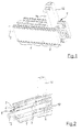
- the pressure medium cylinder with adjustable stroke essentially consists of a front cylinder housing section 1 and a rear Hubeinstellabrough second
- a piston rod 3 leaves the cylinder housing section 1 of the pressure medium cylinder frontally.
- the pressure medium cylinder ortogonal to the longitudinal axis of the piston rod 3 aligned barrier pressure cylinder 4 a, 4 b.
- the Barrier pressure cylinder 4 a and 4 b are used to limit the stroke of the piston rod 3. Die Attachment of both barrier pressure cylinder 4a, 4b on the pressure cylinder takes place here via a detachable clip connection 5.
- the clip connection 5 consists of along the Pressure cylinder on each opposite side surfaces extending double retaining grooves, in which the barrier pressure cylinder 4 a, 4 b via corresponding elastic Moldings are einclipbar.
- the out of the cylinder housing section 1 and the subsequent Hubeinstellabites 2 formed housing integrally as an extruded profile educated.
- the extruded profile has a circular inner cross-section 6 Housing a piston 7 corresponding to the piston rod 3.
- the piston 7 is on both sides via connections for reciprocating the piston rod 3 with compressed air acted upon.
- the circular inner cross section 6 of the extruded profile is outwardly surrounded by a rectangular in principle rectangular cross section 8.
- the rectangular one External cross-section 8 allows the formation of outer surfaces in which the Barrier pressure cylinder - here the barrier pressure cylinder 4b - are attachable.
- a Chamber structure 9 provided, which contributes to weight and material savings.
- the piston rod 3 has an extension, which opens into an end-face disc-like stop 10.
- the stop 10 acts with the Barrier pressure cylinder 4b to form the stroke limiter for the pressure cylinder together.
- the barrier pressure cylinder 4 a (exemplary) an angled Piston rod 11 on.
- the angling takes place here at an angle of 90 ° with respect to normal longitudinal axis of the piston rod, which is also the longitudinal axis of the entire Barrier pressure cylinder 4 a forms.
- the end angled piston rod 11 of Locking pressure cylinder 4 a corresponds with a radial slot 12 on the part of the Hubeinstellabitess 2 of the pressure cylinder.
- the angled piston rod 11 In the retracted position shown the angled piston rod 11, this is outside of the inner cross-section 6 of the Hubeinstellabites 2 placed so that a stroke limitation in this position shown not happened.
- the stroke limitation takes place when the angled piston rod 11 is extended.
- the angled portion of the piston rod 11 then forms a kind of secant through the Inner cross-section 6, so that the - not shown here - stop 10 hereon his Counter-attack finds.
- a plurality of radial slots 12a, 12b, 12c, etc. axially spaced arranged from each other. This can be different stroke lengths by appropriate Adjust positioning of barrier pressure cylinders from the outside.
- the radial slots 12a, 12b, 12c, etc. are here to achieve a minimum pitch of 2mm mutually from two opposite side surfaces 13a and 13b in the Hubeinstellabites 2 of the pressure cylinder introduced.
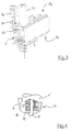
- the angled piston rod 11 of the barrier pressure cylinder 4 ' in this case runs through a bayonet approach 15 of the barrier pressure cylinder 4 '.
- Of the Bayonet approach 15 is about a rotation of the barrier pressure cylinder 4 'by 90 ° with respect to its longitudinal axis of the end position shown by a positive locking with a corresponding projection 16 on the part of Hubeinstellabites 2 of Pressure medium cylinder locked.
- the invention is not limited to the embodiment described above as well as with regard to the possibility of attachment of the barrier pressure cylinder shown modification. Rather, other variants are possible, which from the Inventive idea make use of. So it is of course also possible to attach the Barrier pressure cylinder in the range of Hubeinstellab bainites the pressure cylinder on other way to solve constructive, for example by screwing.
Landscapes
- Engineering & Computer Science (AREA)
- Physics & Mathematics (AREA)
- Fluid Mechanics (AREA)
- Mechanical Engineering (AREA)
- General Engineering & Computer Science (AREA)
- Actuator (AREA)
Applications Claiming Priority (2)
| Application Number | Priority Date | Filing Date | Title |
|---|---|---|---|
| DE10357555 | 2003-12-10 | ||
| DE2003157555 DE10357555B4 (de) | 2003-12-10 | 2003-12-10 | Druckmittelzylinder mit verstellbarem Hub |
Publications (2)
| Publication Number | Publication Date |
|---|---|
| EP1541875A2 true EP1541875A2 (fr) | 2005-06-15 |
| EP1541875A3 EP1541875A3 (fr) | 2006-02-22 |
Family
ID=34485276
Family Applications (1)
| Application Number | Title | Priority Date | Filing Date |
|---|---|---|---|
| EP04106425A Withdrawn EP1541875A3 (fr) | 2003-12-10 | 2004-12-09 | Vérin à pression à course réglable |
Country Status (2)
| Country | Link |
|---|---|
| EP (1) | EP1541875A3 (fr) |
| DE (1) | DE10357555B4 (fr) |
Cited By (2)
| Publication number | Priority date | Publication date | Assignee | Title |
|---|---|---|---|---|
| EP1614908A3 (fr) * | 2004-07-05 | 2007-06-13 | Camozzi S.p.A. | Vérin avec course réglable |
| CN106050793A (zh) * | 2016-07-29 | 2016-10-26 | 泸州合成液压件有限公司 | 一种外锁定油缸 |
Families Citing this family (2)
| Publication number | Priority date | Publication date | Assignee | Title |
|---|---|---|---|---|
| DE102006043928B4 (de) * | 2006-09-14 | 2012-08-09 | Bosch Rexroth Pneumatics Gmbh | Druckmittelzylinder mit verstellbarem Hub |
| DE102007013674B4 (de) | 2007-03-19 | 2011-07-21 | Robert Bosch GmbH, 70469 | Fluidzylinder mit einstellbarem Ausfahrhub |
Family Cites Families (4)
| Publication number | Priority date | Publication date | Assignee | Title |
|---|---|---|---|---|
| GB598604A (en) * | 1942-12-18 | 1948-02-23 | Olaer Patent Co | Improvements in locking devices for hydraulic jacks and the like |
| US3177976A (en) * | 1963-12-18 | 1965-04-13 | Case Co J I | Adjustable stop for hydraulic cylinder |
| US4155433A (en) * | 1977-10-04 | 1979-05-22 | P. L. Porter Company | Stroke-limiting stop for positioning device |
| DE3506491C2 (de) * | 1985-02-23 | 1993-11-04 | Festo Kg | Druckmittelbetaetigter arbeitszylinder |
-
2003
- 2003-12-10 DE DE2003157555 patent/DE10357555B4/de not_active Expired - Fee Related
-
2004
- 2004-12-09 EP EP04106425A patent/EP1541875A3/fr not_active Withdrawn
Cited By (2)
| Publication number | Priority date | Publication date | Assignee | Title |
|---|---|---|---|---|
| EP1614908A3 (fr) * | 2004-07-05 | 2007-06-13 | Camozzi S.p.A. | Vérin avec course réglable |
| CN106050793A (zh) * | 2016-07-29 | 2016-10-26 | 泸州合成液压件有限公司 | 一种外锁定油缸 |
Also Published As
| Publication number | Publication date |
|---|---|
| DE10357555A1 (de) | 2005-07-14 |
| EP1541875A3 (fr) | 2006-02-22 |
| DE10357555B4 (de) | 2007-05-24 |
Similar Documents
| Publication | Publication Date | Title |
|---|---|---|
| DE112007000798B4 (de) | Spann- oder Führungsschiene mit Verliersicherung für Haltebolzen | |
| DE4229930C1 (fr) | ||
| DE4232665A1 (de) | Dreifuss-verriegelungseinrichtung | |
| EP0349942A1 (fr) | Etançon hydraulique en acier | |
| EP3310978B1 (fr) | Arrangement de blocage et un élément de coffrage avec un tel arrangement de blocage | |
| WO2013000459A1 (fr) | Outil combiné de clés à multipans intérieurs | |
| DE2436299A1 (de) | Vorrichtung zur begrenzung des oeffnungswinkels eines fluegels eines fensters, einer tuer oder dergleichen | |
| DE10357555B4 (de) | Druckmittelzylinder mit verstellbarem Hub | |
| DE102004016212B4 (de) | Eckverbindung für einen Fenster-, Tür- oder Fassadenrahmen | |
| EP2787265B1 (fr) | Pièce de cornière d'angle | |
| DE29817335U1 (de) | Spannvorrichtung, insbesondere Kniehebelspannvorrichtung, vornehmlich zur Verwendung im Karosseriebau der Kfz-Industrie | |
| DE202017103840U1 (de) | System zum Sichern eines Fensters oder einer Tür sowie Verwendung einer Stange des Sicherungssystems | |
| DE10357554B4 (de) | Druckmittelzylinder mit einem über lösbare Sperrdruckmittelzylinder verstellbaren Hub | |
| DE19651580C2 (de) | Teleskopstange | |
| DE2923903A1 (de) | Wandbefestigungselement fuer plattenheizkoerper | |
| EP3575539A1 (fr) | Système de cadre pour protection contre les insectes, les pollens ou les particules et protection contre les insectes, le pollen ou les particules | |
| DE9215507U1 (de) | Verbindungsanordnung für Montagebauteile, insbesondere zur Vorwandmontage von Sanitärbauteilen | |
| DE2419462C3 (de) | Vorrichtung zum Verbinden eines Abdeckrahmens mit einem Tragrahmen von Türen oder Fenstern | |
| DE29820770U1 (de) | Dichtungsvorrichtung für den unteren Spalt bei Türen bzw. Toren | |
| DE3542206C2 (de) | Stabförmig ausgebildeter Fassadendübel | |
| DE29705766U1 (de) | Seilverbindung für das Ende eines Drahtseils | |
| DE20003394U1 (de) | Aushebesicherung für eine Heizkörperkonsole | |
| CH696324A5 (de) | U-förmige Einsatzstücke. | |
| DE4013513C2 (de) | Steckverbinder für die geradlinige Stoßverbindung zweier Hohlprofile | |
| DE29714018U1 (de) | Verbindungselement zur Verankerung in einem Holzwerkstück |
Legal Events
| Date | Code | Title | Description |
|---|---|---|---|
| PUAI | Public reference made under article 153(3) epc to a published international application that has entered the european phase |
Free format text: ORIGINAL CODE: 0009012 |
|
| AK | Designated contracting states |
Kind code of ref document: A2 Designated state(s): AT BE BG CH CY CZ DE DK EE ES FI FR GB GR HU IE IS IT LI LT LU MC NL PL PT RO SE SI SK TR |
|
| AX | Request for extension of the european patent |
Extension state: AL BA HR LV MK YU |
|
| PUAL | Search report despatched |
Free format text: ORIGINAL CODE: 0009013 |
|
| AK | Designated contracting states |
Kind code of ref document: A3 Designated state(s): AT BE BG CH CY CZ DE DK EE ES FI FR GB GR HU IE IS IT LI LT LU MC NL PL PT RO SE SI SK TR |
|
| AX | Request for extension of the european patent |
Extension state: AL BA HR LV MK YU |
|
| AKX | Designation fees paid | ||
| STAA | Information on the status of an ep patent application or granted ep patent |
Free format text: STATUS: THE APPLICATION IS DEEMED TO BE WITHDRAWN |
|
| 18D | Application deemed to be withdrawn |
Effective date: 20060823 |
|
| REG | Reference to a national code |
Ref country code: DE Ref legal event code: 8566 |