EP1542061B1 - Méthode de correction de la position d'un faisceau lumineux dans un appareil de balayage - Google Patents
Méthode de correction de la position d'un faisceau lumineux dans un appareil de balayage Download PDFInfo
- Publication number
- EP1542061B1 EP1542061B1 EP05005171A EP05005171A EP1542061B1 EP 1542061 B1 EP1542061 B1 EP 1542061B1 EP 05005171 A EP05005171 A EP 05005171A EP 05005171 A EP05005171 A EP 05005171A EP 1542061 B1 EP1542061 B1 EP 1542061B1
- Authority
- EP
- European Patent Office
- Prior art keywords
- correction data
- light beams
- light beam
- aod
- memory area
- Prior art date
- Legal status (The legal status is an assumption and is not a legal conclusion. Google has not performed a legal analysis and makes no representation as to the accuracy of the status listed.)
- Expired - Lifetime
Links
- 238000000034 method Methods 0.000 title claims description 20
- 230000003287 optical effect Effects 0.000 claims description 87
- 238000010586 diagram Methods 0.000 description 15
- 201000009310 astigmatism Diseases 0.000 description 9
- 230000006866 deterioration Effects 0.000 description 8
- 238000009826 distribution Methods 0.000 description 8
- 230000015572 biosynthetic process Effects 0.000 description 2
- 238000001454 recorded image Methods 0.000 description 2
- 238000011144 upstream manufacturing Methods 0.000 description 2
- 238000005520 cutting process Methods 0.000 description 1
- 238000001514 detection method Methods 0.000 description 1
- 230000000694 effects Effects 0.000 description 1
- 230000004907 flux Effects 0.000 description 1
- 230000006870 function Effects 0.000 description 1
- 230000005484 gravity Effects 0.000 description 1
- 238000004519 manufacturing process Methods 0.000 description 1
- 230000004048 modification Effects 0.000 description 1
- 238000012986 modification Methods 0.000 description 1
- 230000002093 peripheral effect Effects 0.000 description 1
- 238000002360 preparation method Methods 0.000 description 1
- 230000000007 visual effect Effects 0.000 description 1
Images



Classifications
-
- H—ELECTRICITY
- H04—ELECTRIC COMMUNICATION TECHNIQUE
- H04N—PICTORIAL COMMUNICATION, e.g. TELEVISION
- H04N1/00—Scanning, transmission or reproduction of documents or the like, e.g. facsimile transmission; Details thereof
- H04N1/00567—Handling of original or reproduction media, e.g. cutting, separating, stacking
-
- G—PHYSICS
- G02—OPTICS
- G02B—OPTICAL ELEMENTS, SYSTEMS OR APPARATUS
- G02B26/00—Optical devices or arrangements for the control of light using movable or deformable optical elements
- G02B26/08—Optical devices or arrangements for the control of light using movable or deformable optical elements for controlling the direction of light
- G02B26/10—Scanning systems
-
- G—PHYSICS
- G02—OPTICS
- G02B—OPTICAL ELEMENTS, SYSTEMS OR APPARATUS
- G02B26/00—Optical devices or arrangements for the control of light using movable or deformable optical elements
- G02B26/08—Optical devices or arrangements for the control of light using movable or deformable optical elements for controlling the direction of light
- G02B26/10—Scanning systems
- G02B26/101—Scanning systems with both horizontal and vertical deflecting means, e.g. raster or XY scanners
-
- G—PHYSICS
- G02—OPTICS
- G02B—OPTICAL ELEMENTS, SYSTEMS OR APPARATUS
- G02B26/00—Optical devices or arrangements for the control of light using movable or deformable optical elements
- G02B26/08—Optical devices or arrangements for the control of light using movable or deformable optical elements for controlling the direction of light
- G02B26/10—Scanning systems
- G02B26/105—Scanning systems with one or more pivoting mirrors or galvano-mirrors
-
- G—PHYSICS
- G02—OPTICS
- G02B—OPTICAL ELEMENTS, SYSTEMS OR APPARATUS
- G02B27/00—Optical systems or apparatus not provided for by any of the groups G02B1/00 - G02B26/00, G02B30/00
- G02B27/0025—Optical systems or apparatus not provided for by any of the groups G02B1/00 - G02B26/00, G02B30/00 for optical correction, e.g. distorsion, aberration
- G02B27/0031—Optical systems or apparatus not provided for by any of the groups G02B1/00 - G02B26/00, G02B30/00 for optical correction, e.g. distorsion, aberration for scanning purposes
-
- H—ELECTRICITY
- H04—ELECTRIC COMMUNICATION TECHNIQUE
- H04N—PICTORIAL COMMUNICATION, e.g. TELEVISION
- H04N1/00—Scanning, transmission or reproduction of documents or the like, e.g. facsimile transmission; Details thereof
- H04N1/04—Scanning arrangements, i.e. arrangements for the displacement of active reading or reproducing elements relative to the original or reproducing medium, or vice versa
- H04N1/047—Detection, control or error compensation of scanning velocity or position
-
- H—ELECTRICITY
- H04—ELECTRIC COMMUNICATION TECHNIQUE
- H04N—PICTORIAL COMMUNICATION, e.g. TELEVISION
- H04N1/00—Scanning, transmission or reproduction of documents or the like, e.g. facsimile transmission; Details thereof
- H04N1/04—Scanning arrangements, i.e. arrangements for the displacement of active reading or reproducing elements relative to the original or reproducing medium, or vice versa
- H04N1/06—Scanning arrangements, i.e. arrangements for the displacement of active reading or reproducing elements relative to the original or reproducing medium, or vice versa using cylindrical picture-bearing surfaces, i.e. scanning a main-scanning line substantially perpendicular to the axis and lying in a curved cylindrical surface
- H04N1/0607—Scanning a concave surface, e.g. with internal drum type scanners
-
- H—ELECTRICITY
- H04—ELECTRIC COMMUNICATION TECHNIQUE
- H04N—PICTORIAL COMMUNICATION, e.g. TELEVISION
- H04N2201/00—Indexing scheme relating to scanning, transmission or reproduction of documents or the like, and to details thereof
- H04N2201/024—Indexing scheme relating to scanning, transmission or reproduction of documents or the like, and to details thereof deleted
- H04N2201/028—Indexing scheme relating to scanning, transmission or reproduction of documents or the like, and to details thereof deleted for picture information pick-up
- H04N2201/03—Indexing scheme relating to scanning, transmission or reproduction of documents or the like, and to details thereof deleted for picture information pick-up deleted
- H04N2201/031—Indexing scheme relating to scanning, transmission or reproduction of documents or the like, and to details thereof deleted for picture information pick-up deleted deleted
- H04N2201/03104—Integral pick-up heads, i.e. self-contained heads whose basic elements are a light source, a lens and a photodetector supported by a single-piece frame
- H04N2201/0315—Details of integral heads not otherwise provided for
- H04N2201/03154—Additional internal supporting or reinforcing member
-
- H—ELECTRICITY
- H04—ELECTRIC COMMUNICATION TECHNIQUE
- H04N—PICTORIAL COMMUNICATION, e.g. TELEVISION
- H04N2201/00—Indexing scheme relating to scanning, transmission or reproduction of documents or the like, and to details thereof
- H04N2201/04—Scanning arrangements
- H04N2201/047—Detection, control or error compensation of scanning velocity or position
- H04N2201/04701—Detection of scanning velocity or position
- H04N2201/0471—Detection of scanning velocity or position using dedicated detectors
-
- H—ELECTRICITY
- H04—ELECTRIC COMMUNICATION TECHNIQUE
- H04N—PICTORIAL COMMUNICATION, e.g. TELEVISION
- H04N2201/00—Indexing scheme relating to scanning, transmission or reproduction of documents or the like, and to details thereof
- H04N2201/04—Scanning arrangements
- H04N2201/047—Detection, control or error compensation of scanning velocity or position
- H04N2201/04701—Detection of scanning velocity or position
- H04N2201/04729—Detection of scanning velocity or position in the main-scan direction
-
- H—ELECTRICITY
- H04—ELECTRIC COMMUNICATION TECHNIQUE
- H04N—PICTORIAL COMMUNICATION, e.g. TELEVISION
- H04N2201/00—Indexing scheme relating to scanning, transmission or reproduction of documents or the like, and to details thereof
- H04N2201/04—Scanning arrangements
- H04N2201/047—Detection, control or error compensation of scanning velocity or position
- H04N2201/04701—Detection of scanning velocity or position
- H04N2201/04732—Detecting at infrequent intervals, e.g. once or twice per line for main-scan control
-
- H—ELECTRICITY
- H04—ELECTRIC COMMUNICATION TECHNIQUE
- H04N—PICTORIAL COMMUNICATION, e.g. TELEVISION
- H04N2201/00—Indexing scheme relating to scanning, transmission or reproduction of documents or the like, and to details thereof
- H04N2201/04—Scanning arrangements
- H04N2201/047—Detection, control or error compensation of scanning velocity or position
- H04N2201/04701—Detection of scanning velocity or position
- H04N2201/04734—Detecting at frequent intervals, e.g. once per line for sub-scan control
-
- H—ELECTRICITY
- H04—ELECTRIC COMMUNICATION TECHNIQUE
- H04N—PICTORIAL COMMUNICATION, e.g. TELEVISION
- H04N2201/00—Indexing scheme relating to scanning, transmission or reproduction of documents or the like, and to details thereof
- H04N2201/04—Scanning arrangements
- H04N2201/047—Detection, control or error compensation of scanning velocity or position
- H04N2201/04701—Detection of scanning velocity or position
- H04N2201/04744—Detection of scanning velocity or position by detecting the scanned beam or a reference beam
-
- H—ELECTRICITY
- H04—ELECTRIC COMMUNICATION TECHNIQUE
- H04N—PICTORIAL COMMUNICATION, e.g. TELEVISION
- H04N2201/00—Indexing scheme relating to scanning, transmission or reproduction of documents or the like, and to details thereof
- H04N2201/04—Scanning arrangements
- H04N2201/047—Detection, control or error compensation of scanning velocity or position
- H04N2201/04753—Control or error compensation of scanning position or velocity
- H04N2201/04755—Control or error compensation of scanning position or velocity by controlling the position or movement of a scanning element or carriage, e.g. of a polygonal mirror, of a drive motor
-
- H—ELECTRICITY
- H04—ELECTRIC COMMUNICATION TECHNIQUE
- H04N—PICTORIAL COMMUNICATION, e.g. TELEVISION
- H04N2201/00—Indexing scheme relating to scanning, transmission or reproduction of documents or the like, and to details thereof
- H04N2201/04—Scanning arrangements
- H04N2201/047—Detection, control or error compensation of scanning velocity or position
- H04N2201/04753—Control or error compensation of scanning position or velocity
- H04N2201/04758—Control or error compensation of scanning position or velocity by controlling the position of the scanned image area
- H04N2201/0476—Control or error compensation of scanning position or velocity by controlling the position of the scanned image area using an optical, electro-optical or acousto-optical element
-
- H—ELECTRICITY
- H04—ELECTRIC COMMUNICATION TECHNIQUE
- H04N—PICTORIAL COMMUNICATION, e.g. TELEVISION
- H04N2201/00—Indexing scheme relating to scanning, transmission or reproduction of documents or the like, and to details thereof
- H04N2201/04—Scanning arrangements
- H04N2201/047—Detection, control or error compensation of scanning velocity or position
- H04N2201/04753—Control or error compensation of scanning position or velocity
- H04N2201/04789—Control or error compensation of scanning position or velocity in the main-scan direction
-
- H—ELECTRICITY
- H04—ELECTRIC COMMUNICATION TECHNIQUE
- H04N—PICTORIAL COMMUNICATION, e.g. TELEVISION
- H04N2201/00—Indexing scheme relating to scanning, transmission or reproduction of documents or the like, and to details thereof
- H04N2201/04—Scanning arrangements
- H04N2201/047—Detection, control or error compensation of scanning velocity or position
- H04N2201/04753—Control or error compensation of scanning position or velocity
- H04N2201/04793—Control or error compensation of scanning position or velocity using stored control or compensation data, e.g. previously measured data
Definitions
- the present invention relates to a method for correcting a recording position of a light beam according to the preamble of claim 1.
- All of the plurality of light beams or at least light beams other than a basic or reference beam are deflected by individual optical deflecting devices independently to be controlled so that scanning lines formed by respective light beams are put in straight lines at regular intervals on a recording sheet. Since the light beams pass through a common scanning optical system simultaneously, an effect of deterioration with age of the scanning optical system is on a level for all the light beams and therefore it does not matter in general.
- the optical systems emitting the light beams Prior to combining respective light beams in combining optical systems, however, the optical systems emitting the light beams are discrete and therefore deterioration with age of these optical systems directly affects positions between the light beams.
- Light beam intervals or phases on scanning lines fluctuate according to, for example, a temperature change or deterioration with age of the optical systems of respective light beams. It causes a problem that a quality of a recorded image is lowered.
- light beams are split by a beam splitter and the split light beams are guided to a beam position detecting device to detect respective positions of the light beams.
- the positions of the light beams are detected, before they enter the scanning optical system, by a 4-split light beam detecting device, a PSD (position sensing device, two-dimensional position sensor) or the like which is positioned on a conjugate plane optically conjugate with an exposure plane or in a position slightly displaced from the conjugate plane.
- the deflections by the optical deflecting devices are corrected so that the relative positions of the light beams are appropriate.
- Figs. 9A. 9B are diagrams of assistance in explaining the reason why there is caused the disagreement between the recording position on the exposure plane and the beam position detected by the beam position detecting device.
- Fig. 9A shows an optical power distribution of the light beam, with an abscissa axis (x) indicating a position on a plane perpendicular to the light beam and an ordinate axis (p) indicating an optical power (or radiant power). As shown in this diagram the optical power (p) is unsymmetric around the maximum optical power position (x 0 ).
- a 4-split beam detecting device or a PSD is generally used as a beam position detecting device and they are used to detect a center of gravity of an optical power.
- a position (x 1 ) between horizontally equal areas enclosed by the distribution curve of the optical power (p) and the abscissa axis is detected as a beam position.
- a recording density (D) of the light beam on a film on the exposure plane is as shown in Fig. 9B .
- the abscissa axis (x) indicates a position on the exposure plane and the ordinate axis (D) indicates a recording density.
- This recording density (D) is the highest in the position x 0 where the optical power (p) is the maximum.
- the light beam is split before impinging on an beam expander and is introduced to the beam position detecting device.
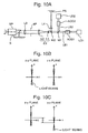
- the split light beam has a small diameter and therefore astigmatism of this light beam is small. It will be described in detail below by using Figs. 10A-10C .
- Fig. 10C shows an enlarged diagram of the image formation on the exposure plane S.
- a difference (astigmatism) ⁇ between a focal position on a z-y plane viewed in the x direction and a focal position on a z-x plane viewed in the y direction. This is because the aperture of the condenser lens L 3 is large as mentioned above.
- a correcting method in accordance with the preamble of claim 1 is known from EP-A-0 840 493 .
- a similar method is known from US-A-4 969 137 .
- the method according to US '137 provides for a tracking error compensation using a real-time servo control.
- the method comprises the step of recording a plurality of light spots on target tracks of an optical disc.
- the disc to be recorded is pre-formatted. Since the light spots should be positioned on the respective tracks, the method detects the intensity distribution of a diffraction pattern of the light beam reflected from the light spots on the discs.
- the method according to EP-A-0 840 493 provides for a multi-beam scanning of an inner face of a cylindrical drum.
- a beam position obtained by a position detector is compared with a normal beam position in a processor. Differences are used as deflection quantity to be compensated.
- the data indicating the deflection quantities correspond to the first correction data used for correcting variations in the deflection angles due to changes in temperature and characteristic changes with time.
- the present invention has been accomplished under the circumstances as aforementioned, and an object thereof is to provide a correcting method capable of preventing a positional relationship of a plurality of light beams from fluctuating according to a temperature change or deterioration with age of an optical system before a scanning optical system and of preventing an image quality from being reduced by unevenness of optical power within a diameter of a light beam or by astigmatism of an optical system.
- this central beam (basic beam) may be guided to the scanning optical system bypassing the optical deflecting device.
- Optical deflecting devices are provided for light beams other than the basic (central) beam. Unless this central beam is used, respective optical deflecting devices may be provided for all the light beams so that all the light beams are deflected.
- the first correction data (which is also referred to as “beam position correction data”, in the specification) may be stored in a first memory area.
- the second correction data (which is also referred to as “recording position correction data” or “additional correction data”, in the specification) may include a plurality of types of recording position correction data correspondingly to resolutions on the light beam exposure plane, which are previously obtained.
- Such second correction data may be stored in a second memory area. With such a constitution, the second correction data corresponding to required output resolutions can be selected out of the second memory area and combined with the first correction data in the first memory area to obtain the final correction data.
- a common memory of the first and second memory areas can be divided into a plurality of memory areas and different memory areas be prepared as first and second memory areas, respectively.
- the first and second memory areas can be configured by separate memory devices.
- the second correction data (recording position correction data) can be obtained as described below. After controlling respective optical deflecting devices by using data of the beam position detecting device so as to match the respective beam positions before an introduction to the scanning optical system, it is checked that there is a difference in the recording positions of the respective light beam where an image is actually output to the exposure plane. If the difference is found, a compensation quantity is obtained for controlling a deflection quantity (angle) of an optical deflecting device to compensate this difference. This compensation quantity of the deflection quantity is considered as recording position correction data, i.e., the second correction data.
- the recording position correction data can also be obtained by measuring intervals between record lines formed by a plurality of light beams onto the exposure plane and making settings so as to keep these line intervals constant. These intervals can be measured by visual observation using a magnifying lens and a measuring gauge. A plurality of types of this recording position correction data can be previously stored in the second memory area according to predetermined or desired resolutions of the image to be recorded.
- a two-dimensional position sensor may be used for the beam position detecting device.
- the light beam may be a laser beam emitted from a laser diode or a solid-state laser.
- the scanning optical system may be of a drum inner surface scanning type.
- optical deflecting devices capable of two-dimensionally deflecting beams is suitable. It is possible to use, for example, two-dimensional acousto-optic deflecting devices or to combine two one-dimensional acousto-optic deflecting devices perpendicularly to each other in the above use.
- electro-optic deflecting devices may be used instead of acousto-optic deflecting devices.
- the second correction data stored in the second memory may include a plurality of types of recording position correction data, each corresponding to output resolutions and any selected recording position correction data may be used as the second correction data.
- a content of the first memory area are rewritten by a rewrite instruction signal appropriately entered.
- a rewrite instruction for the first memory area may be sent out at power-on, once every certain elapsed time, once every image output by a certain number of pages, or a time when an operator desires.
- the light beam scanning apparatus previously stores optimum relative position information of respective light beams as initialization data.
- a beam position of each light beam is detected by the beam position detecting device and then the data is obtained so as to obtain a difference from the initialization data and the difference is considered as beam position correction data.
- This beam position correction data is stored as first correction data in the first memory area.
- This correction data is stored individually in the same manner for all the light beams.
- only correction data corresponding to output resolutions are stored as additional or second correction data, first.
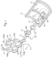
- a light beam scanning apparatus of a drum inner surface scanning type according to a first embodiment of the present invention will be described hereinafter, by referring to Figs. 1 to 6 .
- three laser diodes 10 (10a, 10b, 10c) as light beam output means output laser beams L (L a , L b , L c ) each having almost the same wave length and strength.
- These laser beams L a , L b , and L c are combined by a combining optical system 12 via optical systems which are not shown and via two-dimensional acousto-optic deflecting devices AOD (AOD a , AOD b , AOD c ) as optical deflecting devices.
- the AODs are, as described later, driven by ultrasonic waves having a predetermined frequency generated by transducers, respectively.
- An incident light beam is diffracted with a standing wave produced by the ultrasonic wave.
- the primary diffracted light is selected by a zero-dimensional light cutting plate (not shown).
- the drive signal is modulated by a binary image signal. If a binary image signal is off, outputs of the laser diodes 10 are off.
- Three AODs are used to deflect laser beams L a , L b , and L c in the x-axis direction and in the y-axis direction on the two-dimensional basis in this embodiment, respectively.
- the laser beams L are deflected in two directions perpendicular to each other (in the x-axis direction and in the y-axis direction) to correct bends, intervals, and lengths of the main scanning lines.
- the combining optical system 12 is formed by a total reflection mirror M and half mirrors HM 1 and HM 2 .
- the laser beams L a , L b , and L c are combined to almost a single laser beam, i.e., a combined beam L 0 by this combining optical system 12.
- this combined beam L 0 is shown as a single beam in Figs. 2. to 4 , actually it is split to three non-coaxial beams as shown in Fig. 1 due to component errors or adjustment errors of the combining optical system 12.
- the beam diameter of the combined beam L 0 is enlarged or changed by the lenses L 1 and L 2 constituting the beam expander EX.
- This beam L 0 is guided to an inside of a cylindrical drum D along a central axis thereof.
- a condenser lens L 3 and a spinner SP which constitutes a scanning optical system.
- the spinner SP has a reflective surface with an angle of 45° relative to the central axis (rotary axis), and is rotated by a motor at a high speed.
- the light beam L 0 guided to this spinner SP passes through the beam expander EX and the condenser lens L 3 on the rotation axis, and is focused on the inner peripheral surface of the drum D or on a recording sheet S held on the inner surface of the drum D.
- a beam splitter BS 1 is provided within the arrangement of the beam expander EX.
- the beam splitter BS 1 splits a part of the combined beam L 0 and forms an image on a focal plane P 2 which is conjugate with the focal plane P 1 of the lens L 1 .
- a two-dimensional PSD (two-dimensional position sensor) 14 is provided on the focal plane P 2 or a position slightly deviated therefrom.
- a two-dimensional PSD (two-dimensional position sensor) 14 as a beam position detecting device to detect beam positions of the light beams L a , L b , and L c .
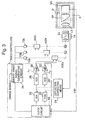
- a reference numeral 16 designates AOD controller as an optical deflecting device control means, which control AODs in synchronization with a rotation angle ⁇ of the spinner SP.
- Fig. 3 there is shown a circuit constitutional example of AOD controller 16.
- Fig. 3 shows a driving circuit only for a single AOD a to simplify the description, while actually the same circuits as the circuit shown in this diagram are arranged for other AOD b and AOD c , respectively.
- These sine-wave signal generating circuit 20 and the cosine-wave signal generating circuit 22 output deflection data in the x direction and in the y direction, respectively.
- the deflection data is added to an AOD driving frequency to deviate the laser beam L in the x-axis direction and in the y-axis direction so as to correct bends, intervals, and lengths of the main scanning lines.
- Correction data is output from deflection correcting means 24 and transferred to these sine-wave signal generating circuit 20 and the cosine-wave signal generating circuit 22. Outputs from these circuits 20 and 22 are corrected on the basis of this correction data, which results in resolving the relative position differences among light beams L a , L b , and L c caused by a temperature change or deterioration with age of the optical system.
- the sine-wave generating circuit 20 and the cosine-wave generating circuit 22 output sine wave voltage signal (Sin) and cosine wave voltage signal (Cos) each having a predetermined amplitude and phase, in synchronism with a rotation angle of the spinner SP, i.e., a clock signal output from the clock circuit 18.
- the deflection correcting means 24 generally output correction data for correcting amplitudes or phases of these sine'waves and the cosine waves. Therefore, this correction data is a constant including a coefficient or factor of the function, in general.
- the deflection correcting means 24 will be described later.
- Voltage-controlled oscillators (VCO) 26 and 28 output frequency modulation signals F (F x , F y ).
- the frequencies of the signals F vary correspondingly to output voltage fluctuations in the sine-wave and cosine-wave generating circuits 20 and 22.
- These signals F are amplified by amplifiers (AMP) 30 and 32, respectively, and then guided to corresponding AODs, so that light beams are deflected in the x and y directions.
- An output from the two-dimensional PSD 14 is inputted via the amplifier 38 to a coordinate detecting circuit 36.
- the coordinate detecting circuit 36 detects a position of a light beam by comparing a plurality of outputs from the two-dimensional PSD 14 with each other.
- the two-dimensional PSD 14 is arranged on a focal plane P 2 ( Fig. 2 ) or in a position slightly deviated from the plane P 2 , and a luminous flux of light beams impinges on the PSD 14 in an expanded condition to some extent. Therefore, the position of the center of the light beam can be detected by comparing the plurality of outputs from the two-dimensional PSD 14.
- a rewrite instruction signal ⁇ instructs the first processing means 42 to start the calculation and rewrites the content of the first memory area 44. While this rewrite instruction ⁇ can be appropriately inputted by an operator, it can also be output automatically when a power switch is turned on or at regular intervals. The rewrite instruction ⁇ can be output when an image output of a predetermined number of pages is completed.
- Second processing means 46 are used to obtain final correction data (f a +f oa ), (f b +f ob ), and (f c +f oc ) by adding additional correction data (recording position correction data) f oa , f ob , and f oc to the beam position correction data f a , f b , and f c , which is stored in the first memory area 44.
- the obtained final correction data is stored in a third memory area 48.
- the second memory area 50 is used to store data corresponding to output resolution 96 res (the number of scanning lines per mm, equivalent to 2,438 dpi) as f oa (96), f ob (96), and f oc (96), data corresponding to 72 res as f oa (72), f ob (72), and f oc (72), and data corresponding to other output resolutions as f oa (N), f ob (N), and f oc (N).
- N indicates an output resolution.
- This additional correction data f oa , f ob , and f oc can be obtained in a procedure shown in Fig. 5 , for example.
- L b is a reference light beam (basic beam).
- a reference beam L b is emitted and then a recording position on the exposure plane or on the recording sheet S is detected to consider this position as an origin (Step 100).
- other light beams L a is emitted and AOD a is controlled so that the beam position of the light beam L a comes to the beam position of the reference beam L b .
- initialized coordinates are the same as those of the beam L b .
- a recording position on the exposure plane of the beam L a is detected and an AOD a driving frequency is changed so that the recording position of the beam L a is coincident with the origin (the above-mentioned recording position of the reference beam L b ) on the exposure plane (Step 102).
- a compensation (or modification) quantity of the AOD a driving frequency needed for the light beam L a to have line intervals corresponding to the desired output resolution is stored in the second memory area 50 as additional (or recording position) correction data f oa (Step 104).
- the same operation is performed (Steps 106 and 108) and the compensation quantity for the beam L c is stored as additional correction data f oc in the second memory area 50 (Steps 102 and 104).
- deflection data output from the sine-wave signal generating circuit 20 and the cosine-wave signal generating circuit 22 are corrected on the basis of the final correction data stored in the third memory area 48.
- the final correction data is intended for the deflection data.
- This final correction data is generally a coefficient or factor for correcting amplitudes or phases of the sine wave voltage signal and the cosine wave voltage signal.
- additional (or recording position) correction data f oa , f ob , and f oc for correcting differences of the recording positions of the beams L a , L b , and L c on the exposure plane are obtained in the procedure shown in Fig. 5 and then stored in the second memory area 50. Subsequently, by using the contents of the second memory area 50 and the first memory area 44, the final correction data (f a +f oa ), (f b +f ob ), and (f c +f oc ) are obtained in the second processing means 46 and stored in the third memory area 48.
- laser diodes 10a, 10b, and 10c are turned on or off on the basis of a binary image signal output from the binary image signal generating circuit 34 for a rotation of the spinner SP.
- the sine-wave generating circuit 20 and the cosine-wave generating circuit 22 of the AOD controller 16 output sine waves and cosine waves corrected on the basis of the contents (the final correction data) of the third memory area 48 and AODs are driven at frequencies corresponding to these sine waves and cosine waves.
- FIG. 8 there is shown a conceptional diagram of a light beam scanning apparatus according to a third embodiment.
- one of three light beams L a , L b , and L c i.e., the light beam L b is set as a basic or reference beam, and only other light beams L a and L c are deflected by the optical deflecting devices AOD a and AOD c .
- an optical deflecting device AOD b is omitted for the basic beam L b .
- the beam splitter BS is disposed in the upstream of the beam expander EX, where the combined beam L 0 is split.
- the beam diameter of the combined beam L 0 is relatively small in the upstream of the beam expander EX, and therefore the beam splitter BS or the lens L4 can be downsized.
- identical reference characters designate the same portions as those in Figs. 1 and 7 , and therefore their description is omitted here.
- a light source for the light beams preferably laser diodes are used, but it is also possible to use a combination of a light source such as a solid-state laser or a gas laser and a modulation device, for example, an acousto-optic device or an electro-optic device. While it is possible to store a difference between data of a beam position detected by a beam position detecting device and previously stored initialization data directly in the first memory area 44, beam position correction data including other elements substantially equivalent to this difference can also be stored in the first memory area and the present invention covers this case.
- a light source such as a solid-state laser or a gas laser
- a modulation device for example, an acousto-optic device or an electro-optic device.
- beam position correction data for maintaining the constant positional relationship of a plurality of light beams are stored.
- the recording positions of respective light beams on an exposure plane are also detected to obtain a second or additional correction data for correcting deviations of the recording positions from the corresponding optimum recording position.
- the additional correction data is added to the beam position correction data to obtain the final correction data, by which the optical deflecting device is controlled. Accordingly, positional deviation of light beams caused by a temperature change or deterioration with age of an optical system prior to a scanning optical system can be corrected on the basis of the beam position correction data.
- the beam position correction data is corrected on the basis of the additional correction data. Therefore, an image quality is prevented from being lowered by unevenness of an optical power distribution within a light beam diameter or astigmatism of the scanning optical system.
- the beam position detecting device can be arranged on a conjugate plane of a light beam exposure plane or in the vicinity thereof.
- the beam position correction data is stored in a first memory area, a plurality of data according to output resolutions is stored in additional correction data, and final correction data can be obtained by using the additional correction data corresponding to an output resolution selected out of the data.
- the additional correction data can be a sum of a compensation quantity for controlling the optical deflecting devices needed for compensating these differences and a correction quantity corresponding to output resolutions.
Landscapes
- Physics & Mathematics (AREA)
- General Physics & Mathematics (AREA)
- Optics & Photonics (AREA)
- Engineering & Computer Science (AREA)
- Multimedia (AREA)
- Signal Processing (AREA)
- Facsimile Scanning Arrangements (AREA)
- Mechanical Optical Scanning Systems (AREA)
Claims (6)
- Procédé de correction d'une position d'enregistrement d'un faisceau lumineux enregistré dans un plan d'exposition par un appareil de balayage à faisceau lumineux, dans lequel au moins un faisceau lumineux d'une pluralité de faisceaux lumineux (La, Lb, Lc) est défléchi par un dispositif de déflexion optique (AODa, AODb, AODc) et ladite pluralité de faisceaux lumineux comprenant le faisceau lumineux défléchi sont combinés et balayés par un système optique de balayage commun vers ledit plan d'exposition, comprenant les étapes consistant à :(a) détecter les positions respectives de ladite pluralité de faisceaux lumineux, avant d'introduire ladite pluralité de faisceaux lumineux dans le système optique de balayage, en utilisant un dispositif de détection de position de faisceau (14) ; et(b) déterminer une première donnée de correction (fa, fb, fc) pour les dispositifs de déflexion optique pour maintenir lesdites positions de faisceau relatives détectées des faisceaux lumineux respectifs constantes et mémoriser ladite première donnée de correction ;
caractérisé en ce qu'il comprend en outre les étapes consistant à :(c) détecter la position d'enregistrement du faisceau lumineux dans ledit plan d'exposition pour déterminer un écart de la position d'enregistrement par rapport à une position optimale, et obtenir une deuxième donnée de correction (f0a, f0b, f0c) pour corriger ledit écart ; et(d) ajouter ladite deuxième donnée de correction à ladite première donnée de correction pour obtenir des données de correction finales (fa+f0a, fb+f0b, fc+f0c) pour commander ledit dispositif de déflexion optique ;dans lequel au moins ladite étape (c) est effectuée avant une opération de balayage. - Procédé selon la revendication 1, dans lequel ledit dispositif de détection de position de faisceau (14) est agencé dans un plan conjugué (P2, P3) dudit plan d'exposition (S) ou dans le voisinage de celui-ci.
- Procédé selon la revendication 1, dans lequel ladite première donnée de correction est mémorisée dans une première zone de mémoire (44) et ladite deuxième donnée de correction est mémorisée dans une deuxième zone de mémoire (50) de manière à avoir une pluralité de types correspondant à des résolutions de sortie dans ledit plan d'exposition ; et dans lequel lesdites données de correction finales des dispositifs de déflexion optique sont obtenues en utilisant ladite première donnée de correction lue dans ladite première zone de mémoire et ladite deuxième donnée de correction correspondant à l'une des résolutions de sortie lue dans ladite deuxième zone de mémoire.
- Procédé selon la revendication 1,
dans lequel le dispositif de déflexion optique est commandé de sorte qu'un faisceau lumineux de référence (Lb) soit apparié séquentiellement à d'autres faisceaux lumineux (La, Lc) à leurs positions d'enregistrement en utilisant des données du dispositif de détection de position de faisceau ;
dans lequel, après la détection d'une différence entre la position d'enregistrement dudit autre faisceau lumineux et la position d'enregistrement dudit faisceau lumineux de référence dans le plan d'exposition, une quantité de compensation pour commander les dispositifs de déflexion optique pour compenser ces différences est déterminée ; et
dans lequel ladite deuxième donnée de correction est obtenue en ajoutant ladite quantité de compensation à une quantité de déflexion de celle correspondant à une résolution de sortie. - Procédé selon la revendication 1, dans lequel la deuxième donnée de correction est fixée de sorte qu'un intervalle de ligne arrive à une valeur constante correspondant à une résolution prédéterminée après la mesure des intervalles de ligne d'une pluralité de lignes enregistrées formées par une pluralité de faisceaux lumineux dans le plan d'exposition.
- Procédé selon la revendication 1, dans lequel lesdites données de correction finales sont utilisées pour commander le fonctionnement dudit dispositif de déflexion optique (AODa, AODb, AODc) dans l'opération de balayage de l'appareil de balayage à faisceau lumineux.
Applications Claiming Priority (3)
| Application Number | Priority Date | Filing Date | Title |
|---|---|---|---|
| JP11374499 | 1999-04-21 | ||
| JP11374499 | 1999-04-21 | ||
| EP00108649A EP1046941B1 (fr) | 1999-04-21 | 2000-04-20 | Méthode de correction de la position d'un faisceau lumineux dans un appareil de balayage |
Related Parent Applications (2)
| Application Number | Title | Priority Date | Filing Date |
|---|---|---|---|
| EP00108649A Division EP1046941B1 (fr) | 1999-04-21 | 2000-04-20 | Méthode de correction de la position d'un faisceau lumineux dans un appareil de balayage |
| EP00108649.5 Division | 2000-04-20 |
Publications (2)
| Publication Number | Publication Date |
|---|---|
| EP1542061A1 EP1542061A1 (fr) | 2005-06-15 |
| EP1542061B1 true EP1542061B1 (fr) | 2010-07-14 |
Family
ID=14620033
Family Applications (3)
| Application Number | Title | Priority Date | Filing Date |
|---|---|---|---|
| EP00108649A Expired - Lifetime EP1046941B1 (fr) | 1999-04-21 | 2000-04-20 | Méthode de correction de la position d'un faisceau lumineux dans un appareil de balayage |
| EP05005171A Expired - Lifetime EP1542061B1 (fr) | 1999-04-21 | 2000-04-20 | Méthode de correction de la position d'un faisceau lumineux dans un appareil de balayage |
| EP05005172A Withdrawn EP1544658A1 (fr) | 1999-04-21 | 2000-04-20 | Méthode de correction de la position d'un faisceau lumineux dans un appareil de balayage |
Family Applications Before (1)
| Application Number | Title | Priority Date | Filing Date |
|---|---|---|---|
| EP00108649A Expired - Lifetime EP1046941B1 (fr) | 1999-04-21 | 2000-04-20 | Méthode de correction de la position d'un faisceau lumineux dans un appareil de balayage |
Family Applications After (1)
| Application Number | Title | Priority Date | Filing Date |
|---|---|---|---|
| EP05005172A Withdrawn EP1544658A1 (fr) | 1999-04-21 | 2000-04-20 | Méthode de correction de la position d'un faisceau lumineux dans un appareil de balayage |
Country Status (3)
| Country | Link |
|---|---|
| US (1) | US6768562B1 (fr) |
| EP (3) | EP1046941B1 (fr) |
| DE (2) | DE60044686D1 (fr) |
Families Citing this family (9)
| Publication number | Priority date | Publication date | Assignee | Title |
|---|---|---|---|---|
| DE10116060B4 (de) * | 2001-03-30 | 2005-01-13 | Tesa Scribos Gmbh | Lithograph mit Triggermaske und Verfahren zum Herstellen digitaler Hologramme in einem Speichermedium |
| DE10116058B4 (de) * | 2001-03-30 | 2006-05-11 | Tesa Scribos Gmbh | Verfahren zum Herstellen digitaler Hologramme in einem Speichermedium und Lithograph zum Herstellen digitaler Hologramme in einem Speichermedium |
| EP1377880B1 (fr) * | 2001-04-12 | 2005-06-01 | tesa scribos GmbH | Lithographe et microscope pourvus d'un masque de declenchement unidimensionnel et procede de production d'hologrammes numeriques dans un moyen memoire |
| JP2004013078A (ja) * | 2002-06-11 | 2004-01-15 | Toshiba Tec Corp | ビーム光走査装置 |
| NL1036321A1 (nl) * | 2007-12-20 | 2009-06-29 | Asml Netherlands Bv | Device control method and apparatus. |
| JP5281923B2 (ja) * | 2009-02-26 | 2013-09-04 | 株式会社日立製作所 | 投射型表示装置 |
| ES2967880T3 (es) | 2016-04-25 | 2024-05-06 | Renishaw Plc | Método de calibración de pluralidad de escáneres en un aparato de fabricación aditiva |
| EP3642664A1 (fr) * | 2017-06-23 | 2020-04-29 | JENOPTIK Optical Systems GmbH | Procédé servant à faciliter l'ajustement d'un élargisseur de faisceau, dispositif d'assistance à l'ajustement et élargisseur de faisceau |
| WO2024243036A1 (fr) * | 2023-05-19 | 2024-11-28 | Nanocellect Biomedical, Inc. | Procédés et systèmes de balayage laser co-linéaire |
Family Cites Families (7)
| Publication number | Priority date | Publication date | Assignee | Title |
|---|---|---|---|---|
| US4462095A (en) * | 1982-03-19 | 1984-07-24 | Magnetic Peripherals Inc. | Moving diffraction grating for an information track centering system for optical recording |
| JPS6069840A (ja) * | 1983-09-22 | 1985-04-20 | Canon Inc | 情報記録又は再生装置 |
| DE3804701A1 (de) * | 1987-03-20 | 1988-09-29 | Hitachi Ltd | Mehrfachlichtfleck-lageregeleinrichtung |
| JPH04459A (ja) * | 1990-04-17 | 1992-01-06 | Matsushita Electric Ind Co Ltd | 多色印字装置 |
| JP3667816B2 (ja) * | 1994-09-07 | 2005-07-06 | 富士写真フイルム株式会社 | 円筒内面走査型画像記録装置 |
| EP1571824B1 (fr) * | 1996-10-30 | 2012-10-24 | FUJIFILM Corporation | Dispositif et méthode de balayage avec des rayons multiples d'une face interne . |
| US6449225B1 (en) * | 1999-08-13 | 2002-09-10 | Zen Research (Ireland), Ltd. | Method and apparatus for reading multiple tracks of an optical disk |
-
2000
- 2000-04-20 EP EP00108649A patent/EP1046941B1/fr not_active Expired - Lifetime
- 2000-04-20 EP EP05005171A patent/EP1542061B1/fr not_active Expired - Lifetime
- 2000-04-20 DE DE60044686T patent/DE60044686D1/de not_active Expired - Lifetime
- 2000-04-20 EP EP05005172A patent/EP1544658A1/fr not_active Withdrawn
- 2000-04-20 DE DE60021017T patent/DE60021017T2/de not_active Expired - Lifetime
- 2000-04-21 US US09/556,478 patent/US6768562B1/en not_active Expired - Lifetime
Also Published As
| Publication number | Publication date |
|---|---|
| DE60044686D1 (de) | 2010-08-26 |
| US6768562B1 (en) | 2004-07-27 |
| DE60021017T2 (de) | 2006-05-18 |
| EP1542061A1 (fr) | 2005-06-15 |
| DE60021017D1 (de) | 2005-08-04 |
| EP1046941B1 (fr) | 2005-06-29 |
| EP1544658A1 (fr) | 2005-06-22 |
| EP1046941A1 (fr) | 2000-10-25 |
Similar Documents
| Publication | Publication Date | Title |
|---|---|---|
| US4841135A (en) | Rotary light beam deflector with revolution surface mirror | |
| EP0827325B1 (fr) | Balayeur à faisceaux multiples avec élément acousto-optique bour balayer des surfaces pour l'enregistrement d'images | |
| US5627670A (en) | Scanning optical apparatus having beam scan controller | |
| EP1542061B1 (fr) | Méthode de correction de la position d'un faisceau lumineux dans un appareil de balayage | |
| US5877494A (en) | Beam error correction using movable correction element | |
| EP0580080B1 (fr) | Appareil enregistreur de rayons lumineux et disque pour cet appareil | |
| EP0825471B1 (fr) | Procédé et dispositif de contrôle du diamètre d'un faisceau | |
| EP1571824B1 (fr) | Dispositif et méthode de balayage avec des rayons multiples d'une face interne . | |
| JP2000194082A (ja) | レンチキュラ―材料のプリントにおけるスキュ―補正 | |
| JP4233728B2 (ja) | 光ビーム走査装置およびその補正方法 | |
| US5267057A (en) | Image scanning and recording method and apparatus for compensating for a pyramidal error of a rotating polygon | |
| EP0827003B1 (fr) | Dispositif de balayage de faisceaux multiples avec un élément actionné mécaniquement pour balayer des surfaces d'images | |
| JP3581503B2 (ja) | 内面走査型光ビーム走査装置およびその制御方法 | |
| JPH09325288A (ja) | マルチビ−ム走査装置 | |
| JP3710567B2 (ja) | 光ビーム走査装置 | |
| JPH0519204A (ja) | 走査光学装置 | |
| JP3432551B2 (ja) | 光ビーム記録装置 | |
| JPS6156316A (ja) | レ−ザプリンタ | |
| JPS6115118A (ja) | レ−ザプリンタ | |
| JPH0934977A (ja) | 光ビーム走査装置 | |
| JP4081474B2 (ja) | 円筒内面走査型画像記録装置 | |
| JPH10170848A (ja) | 光ビーム走査装置およびその制御方法 | |
| JP2001264658A (ja) | ビーム走査装置 | |
| JPH0453288B2 (fr) | ||
| JP2003149582A (ja) | 光ビーム走査方法および装置 |
Legal Events
| Date | Code | Title | Description |
|---|---|---|---|
| PUAI | Public reference made under article 153(3) epc to a published international application that has entered the european phase |
Free format text: ORIGINAL CODE: 0009012 |
|
| 17P | Request for examination filed |
Effective date: 20050309 |
|
| AC | Divisional application: reference to earlier application |
Ref document number: 1046941 Country of ref document: EP Kind code of ref document: P |
|
| AK | Designated contracting states |
Kind code of ref document: A1 Designated state(s): DE FR GB |
|
| AKX | Designation fees paid |
Designated state(s): DE FR GB |
|
| RAP1 | Party data changed (applicant data changed or rights of an application transferred) |
Owner name: FUJIFILM CORPORATION |
|
| 17Q | First examination report despatched |
Effective date: 20071005 |
|
| GRAP | Despatch of communication of intention to grant a patent |
Free format text: ORIGINAL CODE: EPIDOSNIGR1 |
|
| GRAS | Grant fee paid |
Free format text: ORIGINAL CODE: EPIDOSNIGR3 |
|
| GRAA | (expected) grant |
Free format text: ORIGINAL CODE: 0009210 |
|
| AC | Divisional application: reference to earlier application |
Ref document number: 1046941 Country of ref document: EP Kind code of ref document: P |
|
| AK | Designated contracting states |
Kind code of ref document: B1 Designated state(s): DE FR GB |
|
| REG | Reference to a national code |
Ref country code: GB Ref legal event code: FG4D |
|
| REF | Corresponds to: |
Ref document number: 60044686 Country of ref document: DE Date of ref document: 20100826 Kind code of ref document: P |
|
| PLBE | No opposition filed within time limit |
Free format text: ORIGINAL CODE: 0009261 |
|
| STAA | Information on the status of an ep patent application or granted ep patent |
Free format text: STATUS: NO OPPOSITION FILED WITHIN TIME LIMIT |
|
| 26N | No opposition filed |
Effective date: 20110415 |
|
| REG | Reference to a national code |
Ref country code: DE Ref legal event code: R097 Ref document number: 60044686 Country of ref document: DE Effective date: 20110415 |
|
| REG | Reference to a national code |
Ref country code: FR Ref legal event code: PLFP Year of fee payment: 17 |
|
| PGFP | Annual fee paid to national office [announced via postgrant information from national office to epo] |
Ref country code: FR Payment date: 20160309 Year of fee payment: 17 |
|
| PGFP | Annual fee paid to national office [announced via postgrant information from national office to epo] |
Ref country code: GB Payment date: 20160420 Year of fee payment: 17 Ref country code: DE Payment date: 20160412 Year of fee payment: 17 |
|
| REG | Reference to a national code |
Ref country code: DE Ref legal event code: R082 Ref document number: 60044686 Country of ref document: DE Representative=s name: KLUNKER IP PATENTANWAELTE PARTG MBB, DE |
|
| REG | Reference to a national code |
Ref country code: DE Ref legal event code: R119 Ref document number: 60044686 Country of ref document: DE |
|
| GBPC | Gb: european patent ceased through non-payment of renewal fee |
Effective date: 20170420 |
|
| REG | Reference to a national code |
Ref country code: FR Ref legal event code: ST Effective date: 20171229 |
|
| PG25 | Lapsed in a contracting state [announced via postgrant information from national office to epo] |
Ref country code: DE Free format text: LAPSE BECAUSE OF NON-PAYMENT OF DUE FEES Effective date: 20171103 Ref country code: FR Free format text: LAPSE BECAUSE OF NON-PAYMENT OF DUE FEES Effective date: 20170502 |
|
| PG25 | Lapsed in a contracting state [announced via postgrant information from national office to epo] |
Ref country code: GB Free format text: LAPSE BECAUSE OF NON-PAYMENT OF DUE FEES Effective date: 20170420 |