EP1542092B1 - Heizelement, Fixiereinheit und Bilderzeugungsgerät - Google Patents
Heizelement, Fixiereinheit und Bilderzeugungsgerät Download PDFInfo
- Publication number
- EP1542092B1 EP1542092B1 EP04029044.7A EP04029044A EP1542092B1 EP 1542092 B1 EP1542092 B1 EP 1542092B1 EP 04029044 A EP04029044 A EP 04029044A EP 1542092 B1 EP1542092 B1 EP 1542092B1
- Authority
- EP
- European Patent Office
- Prior art keywords
- power supply
- supply unit
- fixing
- unit
- capacitor
- Prior art date
- Legal status (The legal status is an assumption and is not a legal conclusion. Google has not performed a legal analysis and makes no representation as to the accuracy of the status listed.)
- Expired - Lifetime
Links
- 239000003990 capacitor Substances 0.000 claims description 393
- 238000000034 method Methods 0.000 description 163
- 230000008569 process Effects 0.000 description 137
- 238000012986 modification Methods 0.000 description 86
- 230000004048 modification Effects 0.000 description 86
- 238000010586 diagram Methods 0.000 description 71
- 238000001514 detection method Methods 0.000 description 57
- 238000007599 discharging Methods 0.000 description 32
- CNQCVBJFEGMYDW-UHFFFAOYSA-N lawrencium atom Chemical compound [Lr] CNQCVBJFEGMYDW-UHFFFAOYSA-N 0.000 description 28
- 230000006870 function Effects 0.000 description 27
- 230000007423 decrease Effects 0.000 description 21
- 238000012546 transfer Methods 0.000 description 16
- 230000008859 change Effects 0.000 description 11
- 230000006866 deterioration Effects 0.000 description 10
- 238000010438 heat treatment Methods 0.000 description 10
- 230000004044 response Effects 0.000 description 10
- OJIJEKBXJYRIBZ-UHFFFAOYSA-N cadmium nickel Chemical compound [Ni].[Cd] OJIJEKBXJYRIBZ-UHFFFAOYSA-N 0.000 description 7
- 230000002093 peripheral effect Effects 0.000 description 7
- 230000003247 decreasing effect Effects 0.000 description 6
- 230000007246 mechanism Effects 0.000 description 6
- 230000032258 transport Effects 0.000 description 6
- 238000006243 chemical reaction Methods 0.000 description 5
- 230000002542 deteriorative effect Effects 0.000 description 5
- 238000002474 experimental method Methods 0.000 description 5
- 239000011521 glass Substances 0.000 description 5
- 230000003287 optical effect Effects 0.000 description 5
- 238000005070 sampling Methods 0.000 description 5
- QAOWNCQODCNURD-UHFFFAOYSA-N Sulfuric acid Chemical compound OS(O)(=O)=O QAOWNCQODCNURD-UHFFFAOYSA-N 0.000 description 4
- 238000003825 pressing Methods 0.000 description 4
- 238000004140 cleaning Methods 0.000 description 3
- 230000000694 effects Effects 0.000 description 3
- 229910052736 halogen Inorganic materials 0.000 description 3
- 150000002367 halogens Chemical class 0.000 description 3
- 238000012423 maintenance Methods 0.000 description 3
- XEEYBQQBJWHFJM-UHFFFAOYSA-N Iron Chemical compound [Fe] XEEYBQQBJWHFJM-UHFFFAOYSA-N 0.000 description 2
- 230000002159 abnormal effect Effects 0.000 description 2
- 229910052782 aluminium Inorganic materials 0.000 description 2
- XAGFODPZIPBFFR-UHFFFAOYSA-N aluminium Chemical compound [Al] XAGFODPZIPBFFR-UHFFFAOYSA-N 0.000 description 2
- 239000003792 electrolyte Substances 0.000 description 2
- 230000007613 environmental effect Effects 0.000 description 2
- 238000011156 evaluation Methods 0.000 description 2
- 150000002500 ions Chemical class 0.000 description 2
- 238000012544 monitoring process Methods 0.000 description 2
- 230000005855 radiation Effects 0.000 description 2
- 239000012858 resilient material Substances 0.000 description 2
- 229920002379 silicone rubber Polymers 0.000 description 2
- 239000004945 silicone rubber Substances 0.000 description 2
- 238000001179 sorption measurement Methods 0.000 description 2
- 230000001360 synchronised effect Effects 0.000 description 2
- 230000015572 biosynthetic process Effects 0.000 description 1
- 239000000919 ceramic Substances 0.000 description 1
- 239000002131 composite material Substances 0.000 description 1
- 230000001419 dependent effect Effects 0.000 description 1
- 238000003795 desorption Methods 0.000 description 1
- 229910052739 hydrogen Inorganic materials 0.000 description 1
- 239000001257 hydrogen Substances 0.000 description 1
- 230000006698 induction Effects 0.000 description 1
- 229910052742 iron Inorganic materials 0.000 description 1
- 239000000463 material Substances 0.000 description 1
- 230000003446 memory effect Effects 0.000 description 1
- 229910052751 metal Inorganic materials 0.000 description 1
- 239000002184 metal Substances 0.000 description 1
- 238000013021 overheating Methods 0.000 description 1
- 239000004810 polytetrafluoroethylene Substances 0.000 description 1
- 229920001343 polytetrafluoroethylene Polymers 0.000 description 1
- 230000002028 premature Effects 0.000 description 1
- 230000009467 reduction Effects 0.000 description 1
- 238000011160 research Methods 0.000 description 1
- 238000000926 separation method Methods 0.000 description 1
- 238000004904 shortening Methods 0.000 description 1
- 239000002904 solvent Substances 0.000 description 1
Images













Classifications
-
- G—PHYSICS
- G03—PHOTOGRAPHY; CINEMATOGRAPHY; ANALOGOUS TECHNIQUES USING WAVES OTHER THAN OPTICAL WAVES; ELECTROGRAPHY; HOLOGRAPHY
- G03G—ELECTROGRAPHY; ELECTROPHOTOGRAPHY; MAGNETOGRAPHY
- G03G15/00—Apparatus for electrographic processes using a charge pattern
- G03G15/50—Machine control of apparatus for electrographic processes using a charge pattern, e.g. regulating differents parts of the machine, multimode copiers, microprocessor control
- G03G15/5004—Power supply control, e.g. power-saving mode, automatic power turn-off
-
- G—PHYSICS
- G03—PHOTOGRAPHY; CINEMATOGRAPHY; ANALOGOUS TECHNIQUES USING WAVES OTHER THAN OPTICAL WAVES; ELECTROGRAPHY; HOLOGRAPHY
- G03G—ELECTROGRAPHY; ELECTROPHOTOGRAPHY; MAGNETOGRAPHY
- G03G15/00—Apparatus for electrographic processes using a charge pattern
- G03G15/20—Apparatus for electrographic processes using a charge pattern for fixing, e.g. by using heat
- G03G15/2003—Apparatus for electrographic processes using a charge pattern for fixing, e.g. by using heat using heat
-
- G—PHYSICS
- G03—PHOTOGRAPHY; CINEMATOGRAPHY; ANALOGOUS TECHNIQUES USING WAVES OTHER THAN OPTICAL WAVES; ELECTROGRAPHY; HOLOGRAPHY
- G03G—ELECTROGRAPHY; ELECTROPHOTOGRAPHY; MAGNETOGRAPHY
- G03G15/00—Apparatus for electrographic processes using a charge pattern
- G03G15/20—Apparatus for electrographic processes using a charge pattern for fixing, e.g. by using heat
- G03G15/2003—Apparatus for electrographic processes using a charge pattern for fixing, e.g. by using heat using heat
- G03G15/2014—Apparatus for electrographic processes using a charge pattern for fixing, e.g. by using heat using heat using contact heat
- G03G15/2039—Apparatus for electrographic processes using a charge pattern for fixing, e.g. by using heat using heat using contact heat with means for controlling the fixing temperature
- G03G15/205—Apparatus for electrographic processes using a charge pattern for fixing, e.g. by using heat using heat using contact heat with means for controlling the fixing temperature specially for the mode of operation, e.g. standby, warming-up, error
-
- G—PHYSICS
- G03—PHOTOGRAPHY; CINEMATOGRAPHY; ANALOGOUS TECHNIQUES USING WAVES OTHER THAN OPTICAL WAVES; ELECTROGRAPHY; HOLOGRAPHY
- G03G—ELECTROGRAPHY; ELECTROPHOTOGRAPHY; MAGNETOGRAPHY
- G03G15/00—Apparatus for electrographic processes using a charge pattern
- G03G15/80—Details relating to power supplies, circuits boards, electrical connections
-
- G—PHYSICS
- G03—PHOTOGRAPHY; CINEMATOGRAPHY; ANALOGOUS TECHNIQUES USING WAVES OTHER THAN OPTICAL WAVES; ELECTROGRAPHY; HOLOGRAPHY
- G03G—ELECTROGRAPHY; ELECTROPHOTOGRAPHY; MAGNETOGRAPHY
- G03G2215/00—Apparatus for electrophotographic processes
- G03G2215/20—Details of the fixing device or porcess
Definitions
- the present invention generally relates to heaters, fixing units and image forming apparatuses, and more particularly to a heater that is provided with a capacitor and is used to heat various materials or apparatuses, for example, a fixing unit that uses such a heater, and an image forming apparatus, such as a copying machine, a printer and a facsimile machine, that uses such a fixing unit and employs an electrophotography technique.
- a Japanese Laid-Open Patent Application No. 10-10913 proposes delaying a temperature decrease in the fixing unit during the standby state of the fixing unit by supplying to the heat roller a voltage which is a predetermined level lower than a voltage supplied to the heat roller during the normal operating state of the fixing unit. Further, a Japanese Laid-Open Patent Application No.
- 10-282821 proposes charging a secondary battery which forms an auxiliary power supply during the standby state of the fixing unit, so that the time required to raise the temperature of the heat roller can be reduced by supplying the power from a main power supply unit, the secondary battery and a primary battery to the heat roller when the normal operating state of the fixing unit is started.
- a charger charges the capacitor of the auxiliary power supply unit by the power supplied from a main power supply unit, a switching unit switches between the charging of the auxiliary power supply unit and the power supply from the auxiliary power supply unit with respect to an auxiliary heater element, and an amount of power supplied from the auxiliary power supply unit to the auxiliary heater element is adjusted.
- Basic functions of the capacitor include supplying the power from the capacitor to the auxiliary heater element to generate heat therefrom, so that the generated heat can be used to shorten the time required to raise the temperature of the heat roller to the predetermined temperature, and to prevent a fixing temperature from decreasing when the recording medium passes through the fixing unit.
- JP 2002-184554 discloses a heating device and a fixing device for use in an image forming device, the heating and fixing devices comprising a main and an auxiliary heating element which are configured such that noise due to surge current at the time of large power supply or an abrupt current change is reduced.
- Another and more specific object of the present invention is to provide a heater, a fixing unit and an image forming apparatus, which can improve the utilization efficiency of a capacitor that is used as a secondary battery.
- the image forming apparatus of the present invention it is possible to vary the using rate of the auxiliary power supply unit and reduce the amount of power used from the auxiliary power supply unit, so as to efficiently charge the auxiliary power supply unit and optimize the charging of the auxiliary power supply unit.
- a further example of the present invention is to provide an image forming apparatus comprising a heater operable with a main power supply unit and a chargeable auxiliary power supplying unit; the heater comprising a heater part having one or a plurality of heater elements configured to receive power from the main and auxiliary power supplying units; and control means for selecting a first mode that permits discharge of the auxiliary power supply unit when a voltage or power from the auxiliary power supply unit is greater than or equal to a first discharge startable value or, a second mode that permits discharge of the auxiliary power supply unit based on judgement information when the voltage or power from the auxiliary power supply unit is less than the first discharge startable value, the first mode making no reference to the judgement information.
- Still another example of the present invention is to provide a heater operable with a main power supply unit and a chargeable auxiliary power supplying unit, comprising a heater part having one or a plurality of heater elements configured to receive power from the main and auxiliary power supplying units; and control means for changing a usage of power and/or an amount of power stored in the auxiliary power supply unit based on an input voltage of the main power supply unit.
- the heater of the present invention it is possible to reduce the waiting time that is required until the temperature of a fixing unit reaches the predetermined fixing temperature when the main power supply unit is turned ON, reduce the waiting time that is required for the temperature of the fixing unit to reach the predetermined fixing temperature from the standby state such as a sleep mode and a power save mode of the image forming apparatus, and improve the productivity when continuously carrying out an image forming process with respect to the consecutively supplied recording media.
- a further example of the present invention is to provide a heater operable with a main power supply unit and a chargeable auxiliary power supplying unit, comprising a heater part having one or a plurality of heater elements configured to receive power from the main and auxiliary power supplying units; and control means for changing a usage of power and/or an amount of power stored in the auxiliary power supply unit based on an environment temperature.
- the heater of the present invention it is possible to reduce the waiting time that is required until the temperature of a fixing unit reaches the predetermined fixing temperature when the main power supply unit is turned ON, reduce the waiting time that is required for the temperature of the fixing unit to reach the predetermined fixing temperature from the standby state such as a sleep mode and a power save mode of the image forming apparatus, and improve the productivity when continuously carrying out an image forming process with respect to the consecutively supplied recording media.
- Another example of the present invention is to provide a heater operable with a main power supply unit and a chargeable auxiliary power supplying unit, comprising a heater part having one or a plurality of heater elements configured to receive power from the main and auxiliary power supplying units; and control means for changing a usage of power and/or an amount of power stored in the auxiliary power supply unit based on the amount of power stored in the auxiliary power supply unit.
- Still another example of the present invention is to provide a fixing unit comprising a heater operable with a main power supply unit and a chargeable auxiliary power supplying unit, the heater comprising a heater part having one or a plurality of heater elements configured to receive power from the main and auxiliary power supplying units; and control means for changing a usage of power and/or an amount of power stored in the auxiliary power supply unit based on predetermined information selected from a group consisting of an input voltage of the main power supply unit, an environment temperature and the amount of power stored in the auxiliary power supply unit.
- Another example of the present invention is to provide an image forming apparatus comprising a heater operable with a main power supply unit and a chargeable auxiliary power supplying unit, and comprising a heater part having one or a plurality of heater elements configured to receive power from the main and auxiliary power supplying units; a voltage detector configured to detect an output voltage of the main power supply unit; control means for charging the auxiliary power supply unit by the power from the main power supply unit until an output voltage of the auxiliary power supply unit becomes greater than or equal to a target voltage; and a fixing part, heated by the heater part, and configured to fix an image on a recording medium that makes sliding contact with the heater part or pass close to the heater part, the control means increasing the target voltage when the output voltage of the main power supply unit detected by the voltage detector decreases.
- the image forming apparatus of the present invention it is possible to reduce the time required to start the image forming apparatus regardless of the power supply state of the main power supply unit, so as to realize a high-speed image forming process, and to simultaneously realize a long serviceable life of the auxiliary power supply unit and a satisfactory image quality of the formed image.
- the image forming apparatus of the present invention it is possible to reduce the time required to start the image forming apparatus regardless of the power supply state of the main power supply unit, so as to realize a high-speed image forming process, and to simultaneously realize a long serviceable life of the auxiliary power supply unit and a satisfactory image quality of the formed image.
- the photoelectric conversion element 28 receives the reflected light from the document D that is imaged thereon by the optical system 27, and the image of the document D is scanned and read by moving the light source 26 and a portion of the optical system 27, for example. After the image of the document D is read, the document D is transported in a direction of an arrow B2 by the rotation of the transport belt 23, and ejected onto the media eject tray 14. The documents D are successively supplied onto the contact glass 14 one by one, and the document image of each document D is read by the image reading unit 11.
- a photoconductive body 30 is provided within the image forming unit 12 as an image bearing member.
- the photoconductive body 30 has a drum shape, for example.
- the photoconductive body 30 is driven by a driving unit (not shown) and is rotated clockwise in FIG. 1 , and an outer peripheral surface of the photoconductive body 30 is charged to a predetermined potential by a charging unit 31.
- a write unit 32 irradiates a laser beam L that has been modulated depending on image information of the document image read by the read unit 25 by driving a laser light source within the write unit 32 by the image information. This laser beam L exposes the charged surface of the photoconductive body 30 so as to form an electrostatic latent image on the surface of the photoconductive body 30.
- FIG. 2 is a cross sectional view conceptually showing a structure of an embodiment of a fixing unit according to the present invention that is used in the image forming apparatus shown in FIG. 1 .
- FIG. 2 shows the fixing unit 36 which applies heat and pressure on the toner image that is transferred onto the recording medium P.
- FIG. 3 is a circuit diagram showing a structure of a first embodiment of a heater according to the present invention that is provided in the fixing unit 36.
- the fixing unit 36 shown in FIG. 2 includes a fixing roller 40 and a pressure roller 41 which is urged to press against the fixing roller 40 by a pressure applying member or means (not shown).
- a heater part 2 is provided within the fixing roller 40.
- the heater part 2 is made up of a main heater element 2a and an auxiliary heater element 2b that are formed by halogen heaters, for example.
- the fixing roller 40 and the pressure roller 41 form a nip part N which applies pressure and heat on a toner T that is on the recording medium P passing between the fixing roller 40 and the pressure roller 41.
- the fixing roller 40 may be made of an aluminum roller having an outer diameter 0 of 40 mm and a thickness t of 0.7 mm.
- This thickness t of the fixing roller 40 enables the temperature of the fixing roller 40 to be raised within 30 seconds to a temperature capable of carrying out a fixing process, and also prevents the fixing roller 40 from breaking when a load or pressure necessary for forming the nip part N to carry out the fixing process is applied on the fixing roller 40.
- the thickness t of the fixing roller 40 was on the order of approximately 5.0 mm to 10 mm and thick.
- a separation or release layer made of FPA, PTFE or the like is desirably provided on an outermost layer of the fixing roller 40.
- the main heater element 2a generates heat by being supplied with the power from the main power supply unit 3
- the auxiliary heater element 2b generates heat by being supplied with the power from the auxiliary power supply unit 4.
- the fixing roller 40 is heated by these heater elements 2a and 2b.
- the main power supply unit 3 receives the power supplied from a commercial power supply within the image forming apparatus in which the heater 1 is provided.
- the main power supply unit 3 has a function of adjusting the power supplied from an electric outlet into a voltage suited for the heater part 2, for example, but a power supply unit having such a function is known and an illustration and description thereof will be omitted.
- the capacitor C having such module structures have a capacitance that is sufficient for making a power supply for approximately 1 minute to approximately 2 minutes.
- the power decreases as the voltage decreases and the danger of fire is positively suppressed.
- the danger of electrification is also suppressed because the voltage is on the order of approximately 50 V for the capacitor C.
- a target charging voltage of the capacitor is set lower than the rated voltage by taking into consideration the inconsistencies in a voltage circuit and the durability of the capacitor cells, so as to improve the reliability of the capacitor C.
- the capacitor C may have a module structure having cells with an electrostatic capacitance lower than approximately 100 F connected in parallel, however, from the point of view of reducing electronic circuits required with respect to each cell and facilitating detection of abnormal cells, it is desirable that all of the cells are connected in series.
- the electric double layer capacitor has no dielectric, and utilizes adsorption and desorption reactions (charging and discharging) of an individual electrode and an ion adsorption layer of an electric double layer where charges of solvent molecules or ions formed at a solution interface are concentrated.
- the electric double layer capacitor can strongly withstand repeated charging and discharging to realize a long serviceable life, and does not require maintenance.
- the electric double layer capacitor is also gentle on the environment, and has a short charging time compared to other types of batteries.
- the charging and discharging efficiency of the electric double layer capacitor is also high. In addition, it is easy to know the remaining power of the electric double layer capacitor by making a voltage detection.
- electric double layer capacitors having a high electrostatic capacitance on the order of approximately several ten thousand F and an energy density on the order of approximately several tens of Wh/kg have been developed, and active research is being made to realize electric double layer capacitors with an even higher electrostatic capacitance.
- the controller 8 includes a switch 9 and a CPU 10, and carries out a control to turn ON and OFF the supply of the power from the auxiliary power supply unit 4 to the auxiliary heater element 2v depending on predetermined conditions that will be described later. Only the part of the controller 8 related to the control of the heater part 2 is shown in FIG. 3 . However, the structure of the controller 8 is not limited to that shown in FIG. 3 , and the controller 8 may have various other structures such as a structure which is used in common for the control of the heater part 2 and the control of the entire image forming apparatus, for example. In addition, the connection of the controller 8 for varying out the control with respect to the auxiliary power supply unit 4 is not limited to that shown in FIG. 3 .
- the switching unit 7 is switched to connect the auxiliary power supply unit 4 to the charger 6, so as to charge the auxiliary power supply unit 4 by the power supplied from the main power supply unit 3. If a large power needs to be supplied to the heater part 2 again, a large amount of energy is supplied to the heater part 2 by supplying not only the power from the main power supply unit 3 but also the power from the auxiliary power supply unit 4 to the heater part 2.
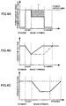
- FIG. 4C shows the output voltage of the capacitor C for a case where the capacitor C is used for the purpose of preventing the surface temperature of the fixing roller 40 from decreasing due to the lack of power supplied to the heater part 2 when the recording media P are successively supplied to the fixing unit 36.
- the entire image forming apparatus is cold immediately after it is started, and the power tends to lack.
- the switching unit 7 is switched to connect the auxiliary power supply unit 4 to the auxiliary heater element 2b, so as to supply the power from the capacitor C to the auxiliary heater element 2b of the heater part 2.
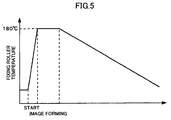
- FIG. 5 is a diagram showing a temperature change of the fixing roller 40.
- the surface temperature of the fixing roller 40 is low in the standby state, and rises to the predetermined fixing temperature when the heater 1 is started due to the heat generated by both the main and auxiliary heater elements 2a and 2b, as described above.
- FIG. 5 shows a case where the predetermined fixing temperature is 180°C.
- the surface temperature of the fixing roller 40 is maintained approximately to the predetermined fixing temperature, and gradually decreases after the image forming process ends.
- the surface temperature of the fixing roller 40 decreases to room temperature (temperature of a site where the image forming apparatus is set up) or to a temperature inside the image forming apparatus.
- a PID control or the like is employed to control the operation of the heater 1, that is, both the main and auxiliary power supply units 3 and 4 are driven and controlled.
- the auxiliary heater element 2b may mainly bear the burden of heating of the fixing roller 40.
- FIG. 6 is a diagram showing a relationship of the control of the power supply from the main power supply unit 3 to the main heater element 2a and the control of the power supply from the auxiliary power supply unit 4 to the auxiliary heater element 2b.
- a sampling time of the control of the power supply from the main power supply unit 3 to the main heater element 2a is 1 second (t1: between AC and AC)
- a sampling time of the control of the power supply from the auxiliary power supply unit 4 to the auxiliary heater element 2b is 0.3 second or 1/3 second to be more accurate (t2: between AC and DC, between DC and DC, and between DC and AC)
- the surface temperature of the fixing roller 40 reaches the predetermined fixing temperature by first supplying the power from the main power supply unit 3 to the main heater element 2a, and the heat is thereafter not applied to the fixing roller 40.
- the surface temperature of the fixing roller 40 begins to decrease.
- the sampling time of the control of the power supply from the main power supply unit 3 that occurs after 1 second, no power is supplied to the main heater element 2a and no heat is applied from the main heater element 2a to the fixing roller 40.
- the sampling time of the control of the power supply from the auxiliary power supply unit 4 to the auxiliary heater element 2b occurs after 0.3 second, and if the surface temperature of the fixing roller 40 has decreased to a certain temperature, the capacitor C of the auxiliary power supply unit 4 discharges to supply the power to the auxiliary heater element 2b, and a similar heat applying process may further be carried out after another 0.3 second.
- the surface temperature of the fixing roller 40 may have returned to the predetermined fixing temperature that is indicated as an "AC/DC OFF temperature" in FIG. 6 , and it may be judged unnecessary to apply the heat from the main heater element 2a to the fixing roller 40. If such a situation occurs repeatedly, the main power supply unit 3 and the main heater element 2a, which should mainly operate originally, may remain OFF, and instead, only the auxiliary power supply unit 4 and the auxiliary heater element 2b may contribute to the heating and the temperature maintenance of the fixing roller 40.
- the surface temperature of the fixing roller 40 is mainly controlled by the auxiliary power supply unit 4 and the auxiliary heater element 2b, the wear or deterioration of the capacitor C is accelerated to thereby shorten the serviceable life of the auxiliary power supply unit 4. Even if the electric double layer capacitor having the relatively long serviceable life is used for the auxiliary power supply unit 4, the shortening of the serviceable life of the auxiliary power supply unit 4 cannot be avoided in this situation.
- the operation of supplying the power from the main power supply unit 3 to the main heater element 2a and the operation of supplying the power from the auxiliary power supply unit 4 to the auxiliary heater element 2b are linked based on information that is related to the heater 1 (or heater part 2), so as to minimize the use of the capacitor C and thus prevent premature wear or deterioration of the capacitor C.
- the amount of power supplied from the main power supply unit 3 is used for the information that is related to the heater 1 (or heater part 2), as the conditions used to vary the amount of power supplied from the capacitor C.
- a known detecting unit or means may be used to detect the amount of power supplied from the main power supply unit 3.
- the controller 8 varies the amount of power supplied from the capacitor C per unit time depending on the change in the detected amount of power supplied from the main power supply unit 3, where the unit time is an arbitrary length of time.
- the auxiliary power supply unit 4 formed by the DC power supply is prevented from operating and discharging the capacitor C to turn ON the auxiliary heater element 2b.
- the discharge of the capacitor C is suppressed, it is possible to shorten the charging time of the capacitor C.
- the amount of power supplied to the main power supply unit 3 from the commercial power supply may be used for the information that is related to the heater 1 (or heater part 2), as the conditions used to vary the amount of power supplied from the capacitor C.
- the voltage supplied from the main power supply unit 3 is used for the information that is related to the heater 1 (or heater part 2), as the conditions used to vary the amount of power supplied from the capacitor C.
- a known detecting unit or means may be used to detect the voltage supplied from the main power supply unit 3.
- the controller 8 varies the amount of power supplied from the capacitor C per unit time depending on the change in the detected voltage supplied from the main power supply unit 3, where the unit time is an arbitrary length of time.
- the temperature of the pressure roller 41 which functions as a pressure applying member with respect to the fixing roller 40 is used for the information that is related to the heater 1 (or heater part 2), as the conditions used to vary the amount of power supplied from the capacitor C.
- a known temperature sensor or temperature detecting means may be used to detect the temperature of the pressure roller 41.
- the controller 8 varies the amount of power supplied from the capacitor C per unit time depending on the change in the detected temperature of the pressure roller 41, where the unit time is an arbitrary length of time.
- the amount of power supplied from the capacitor C per unit time is increased. If the temperature of the pressure roller 41 is lower than or equal to the predetermined value, the heat of the fixing roller 40 will be absorbed by the pressure roller 41 to raise the temperature of the pressure roller 41 unless the amount of power supplied to the auxiliary heater element 2b by the discharge of the capacitor C is increased. Accordingly, the ON time of the auxiliary heater element 2b by the discharge of the capacitor C is increased in this case, so as to sufficiently raise the surface temperature of the fixing roller 40. Otherwise, an incomplete fixing of the image may occur at the fixing unit 36.
- the environment temperature is used for the information that is related to the heater 1 (or heater part 2), as the conditions used to vary the amount of power supplied from the capacitor C.
- the environment temperature may be the temperature of the heater 1, the temperature of the fixing unit 36 or the temperature of the image forming apparatus.
- a nip temperature of the nip part N between the fixing roller 40 and the pressure roller 41 may be used as the environment temperature.
- the environment temperature may be selected from the internal or external temperature of the heater 1, the internal or external temperature of the fixing unit 36, and the internal or external temperature of the image forming apparatus.
- the controller 8 functions as an amount varying unit or means for reducing the amount of power supplied from the auxiliary power supply unit 4 per unit time.
- the ON time of the auxiliary heater element 2b is reduced in this case, so as to suppress the discharge of the capacitor C and to shorten the charging time of the capacitor C.
- the amount of power supplied from the capacitor C per unit time is increased. If the environment temperature is lower than or equal to the predetermined value, the surface temperature of the fixing roller 40 will be lower than the predetermined fixing temperature unless the amount of power supplied to the auxiliary heater element 2b by the discharge of the capacitor C is increased. Accordingly, the ON time of the auxiliary heater element 2b by the discharge of the capacitor C is increased in this case, so as to sufficiently raise the surface temperature of the fixing roller 40. Otherwise, an incomplete fixing of the image may occur at the fixing unit 36.
- the controller 8 functions as an amount varying unit or means for reducing the amount of power supplied from the auxiliary power supply unit 4 per unit time.
- the controller 8 functions as an amount varying unit or means for reducing the amount of power supplied from the auxiliary power supply unit 4 per unit time.
- the temperature of the pressure roller 41 remains sufficiently high.
- the amount of heat absorbed from the fixing roller 40 by the pressure roller 41 is small, and thus, the amount of power supplied to the auxiliary heater element 2b by the discharge of the capacitor C may be small.
- the ON time of the auxiliary heater element 2b is reduced in this case, so as to suppress the discharge of the capacitor C and to shorten the charging time of the capacitor C, similarly to the third modification of the first embodiment described above.
- the amount of power supplied from the capacitor C per unit time is increased. If the number of recording media P for the previous job is lower than or equal to the predetermined value, the temperature of the pressure roller 41 will be low, and the heat of the fixing roller 40 will be absorbed by the pressure roller 41 to raise the temperature of the pressure roller 41 unless the amount of power supplied to the auxiliary heater element 2b by the discharge of the capacitor C is increased. Accordingly, the ON time of the auxiliary heater element 2b by the discharge of the capacitor C is increased in this case, so as to sufficiently raise the surface temperature of the fixing roller 40. Otherwise, an incomplete fixing of the image may occur at the fixing unit 36.
- the number of recording media P subjected to the image forming process during the previous job may be used in place of the number of recording media P that passed through the fixing unit 36 during the previous job.
- the time interval between a previous job and a present job is used for the information that is related to the heater 1 (or heater part 2), as the conditions used to vary the amount of power supplied from the capacitor C.
- a known timer or time measuring means may be used to measure the time interval between the previous job and the present job.
- the controller 8 varies the amount of power supplied from the capacitor C per unit time depending on the time interval between the previous job and the present job, where the unit time is an arbitrary length of time.
- the amount of power supplied from the capacitor C per unit time is increased. If the time interval between the previous job and the present job is longer than or equal to the predetermined value, the temperature of the pressure roller 41 will be low, and the heat of the fixing roller 40 will be absorbed by the pressure roller 41 to raise the temperature of the pressure roller 41 unless the amount of power supplied to the auxiliary heater element 2b by the discharge of the capacitor C is increased. Accordingly, the ON time of the auxiliary heater element 2b by the discharge of the capacitor C is increased in this case, so as to sufficiently raise the surface temperature of the fixing roller 40. Otherwise, an incomplete fixing of the image may occur at the fixing unit 36.
- the work time of a previous job is used for the information that is related to the heater 1 (or heater part 2), as the conditions used to vary the amount of power supplied from the capacitor C.
- a known timer or time measuring means may be used to measure the work time of the previous job.
- the controller 8 varies the amount of power supplied from the capacitor C per unit time depending on the work time of the previous job, where the unit time is an arbitrary length of time.
- the amount of power supplied from the capacitor C per unit time is increased. If the work time of the previous job is shorter than or equal to the predetermined value, the temperature of the pressure roller 41 will be low, and the heat of the fixing roller 40 will be absorbed by the pressure roller 41 to raise the temperature of the pressure roller 41 unless the amount of power supplied to the auxiliary heater element 2b by the discharge of the capacitor C is increased. Accordingly, the ON time of the auxiliary heater element 2b by the discharge of the capacitor C is increased in this case, so as to sufficiently raise the surface temperature of the fixing roller 40. Otherwise, an incomplete fixing of the image may occur at the fixing unit 36.
- the controller 8 of the heater 1 variably controls the amount of power supplied from the capacitor C.
- a control unit or means for variably controlling the amount of power supplied from the capacitor C is not limited to such, and may be provided in the fixing unit 36 or in the image forming apparatus, for example.
- a control unit or means used to control other functions may be used in common for the purposes of variably controlling the amount of power supplied from the capacitor C.
- the surface temperature of the fixing roller having a small heat capacity drops rapidly when the heat of the fixing roller is absorbed by the recording medium and the toner when fixing the toner image transferred on the recording medium. For this reason, the surface temperature of the fixing roller having the small heat capacity becomes lower than the lower limit of the fixing temperature, and an incomplete fixing easily occurs.
- An example of the present invention is designed to suppress the above described problems of the conventional and conceivable image forming apparatuses.
- the example of the image forming apparatus, the heater and the the fixing unit may have basic structures that are the same as those of the embodiment described above in conjunction with FIGS. 1 through 5 , and an illustration and description thereof will be omitted.
- the switching unit 7 shown in FIG. 3 is switched to connect the auxiliary power supply unit 4 to the charger 6, so that the charger charges the capacitor C of the auxiliary power supply unit 4 to a voltage (or power) that is greater than or equal to a first value from which the discharging of the capacitor C is permitted (hereinafter simply referred to as a first dischargeable value) by the power supplied from the main power supply unit 3.
- the main switch 5 is turned ON and OFF so that the surface temperature of the fixing roller 40 is maintained at a standby temperature that is lower than the fixing temperature.
- the main switch 5 When generating heat in the heater part 2 by starting the heater 1, the main switch 5 is turned ON to supply the power from the main power supply unit 3 to the main heater element 2a via the main switch 5. At the same time, if the voltage (or power) from the auxiliary power supply unit 4 is greater than or equal to the first dischargeable value, the switching unit 7 is switched to supply the power from the auxiliary power supply unit 4 to the auxiliary heater element 2b, so that a large power is supplied to the heater part 2. Since this large power is supplied to the heater part 2 from both the main power supply unit 3 and the auxiliary power supply unit 4, the temperature of the fixing roller 40 within the heater part 2 can be raised to the predetermined temperature within a short time.
- the capacitor C When the capacitor C is discharged to the voltage at which the discharging stops, it is of course necessary to charge the capacitor C to prepare for the next discharge.
- the voltage of the capacitor C decreases due to natural discharge, and it may take time to start the image forming process in such a case due to the waiting time required, that is, the charging time of the capacitor C.
- a method has been proposed to automatically detect the voltage of the capacitor C and to automatically charge the capacitor C depending on the detected voltage. But in any case, in order to enable discharge of the capacitor C that has already been discharged, it is first necessary to charge the capacitor C to a predetermined minimum voltage from which the capacitor C may be discharged.
- the discharge time required to charge the capacitor C may be on the order of approximately several tens of seconds to approximately 2 minutes and relatively short, but still, the capacitor C cannot be used (that is, discharged) during this charging time.
- FIG. 7 is a diagram showing a voltage decrease of the capacitor C which is used to heat the fixing roller 40 of the image forming apparatus of this second embodiment due to discharging when the charging is started from a discharge stopped state and the charging is stopped in a fully charged state where the charging is made to an upper limit value.
- the ordinate indicates the voltage of the capacitor C
- the abscissa indicates the time in arbitrary units.
- the voltage of the capacitor C is 50 V in the fully charged state
- a minimum dischargeable voltage at which the capacitor C may be discharged is 30 V
- a voltage at which the discharge of the capacitor C stops is 15 V.
- the capacitor voltage is 15 V at a time t1 when the charging starts, 30 V at a time t2 when the capacitor voltage is the minimum dischargeable voltage at which the capacitor C may be discharged, and is 50 V at a time t3 when the capacitor C is fully charged and the charging of the capacitor C is stopped.
- the CPU 10 controls the switch 9 to permit the discharge of the auxiliary power supply unit 4.
- the CPU 10 controls the switch based on the predetermined judgement information to permit the discharge of the auxiliary power supply unit 4.
- the voltages of 50 V, 30 V and 15 V are mere examples and various other voltage values may be used in this second embodiment.
- the voltage of the capacitor C may be 45 V in the fully charged state
- the minimum dischargeable voltage at which the capacitor C may be discharged may be 32 V
- the voltage at which the discharge of the capacitor C stops may be 2 V.
- the time interval from the time t1 to the time t2 may be less than 1 minute
- the time interval from the time t1 to the time t3 may be less than 2 minutes, such as 1 minute to 1.5 minutes.
- an input voltage that is input to the main power supply unit 3 from the commercial power supply is used for the predetermined judgement information that is related to the heater 1.
- a known detecting unit or means may be used to detect the input voltage of the main power supply unit 3.
- the controller 8 controls the switch 9 to permit the discharge of the auxiliary power supply unit 4 depending on the detected input voltage of the main power supply unit 3.
- a known detecting unit or means may be used to detect the voltage supplied from the auxiliary power supply unit 4.
- the controller 8 turns the switch 9 ON even when the auxiliary power supply unit 4 is in an intermediate charging state and is not yet fully charged to the upper limit value, so as to permit discharge from the auxiliary power supply unit 4 and supply the voltage from the auxiliary power supply unit 4 to the auxiliary heater element 2b.
- the controller 8 turns the switch 9 ON only when the auxiliary power supply unit 4 is in a fully charged state and is charged to the upper limit value, so as to permit discharge from the auxiliary power supply unit 4 and supply the voltage from the auxiliary power supply unit 4 to the auxiliary heater element 2b.
- the amount of power supplied to the auxiliary heater element 2b by discharging the capacitor C may be small.
- the discharge from the auxiliary power supply unit 4 is permitted even in the intermediate charging state where the capacitor C has not yet fully charged to the upper limit value, so as to eliminate the waiting time prior to the image forming process, which would otherwise be necessary to charge the capacitor C.
- the input voltage of the main power supply unit 3 is lower than or equal to the predetermined value, it may be judged that a small amount of power is supplied from the main power supply unit 3. Accordingly, if the input voltage of the main power supply unit 3 is lower than or equal to the predetermined value, the surface temperature of the fixing roller 40 will not rise sufficiently and an incomplete fixing of the image may occur at the fixing unit 36 unless a large amount of power is supplied from the auxiliary power supply unit 4 to the auxiliary heater element 2b by discharging the capacitor C.
- the switch 9 is turned ON to permit discharge from the auxiliary power supply unit 4 only when the capacitor C is fully charged to the upper limit value, so as to prevent the incomplete fixing at the fixing unit 36.
- the auxiliary power supply unit 4 By controlling the discharge from the auxiliary power supply unit 4 in the above described manner, it is possible to optimize the discharge from the auxiliary power supply unit 4. Moreover, such a discharge control may be employed regardless of whether the main power supply unit 3 is formed by an AC power supply or a DC power supply. Furthermore, the predetermined value which is used as a threshold value for determining whether or not to permit discharge from the auxiliary power supply unit 4 may be appropriately determined based on experiments or the like. Predetermined values used similarly as threshold values in the subsequent modifications of the second embodiment may also be determined appropriately based on experiments or the like.
- the voltage supplied from the main power supply unit 3 may be used for the predetermined judgement information that is related to the heater 1.
- the temperature of the pressure roller 41 is used for the predetermined judgement information that is related to the heater 1.
- a known temperature sensor or temperature detecting means may be used to detect the temperature of the pressure roller 41.
- the controller 8 controls the switch 9 to permit the discharge of the auxiliary power supply unit 4 depending on the detected temperature of the pressure roller 41.
- the controller 8 turns the switch 9 ON only when the auxiliary power supply unit 4 is in a fully charged state and is charged to the upper limit value, so as to permit discharge from the auxiliary power supply unit 4 and supply the voltage from the auxiliary power supply unit 4 to the auxiliary heater element 2b.
- the heat of the fixing roller 40 will be absorbed by the pressure roller 41 to raise the temperature of the pressure roller 41 unless the amount of power supplied to the auxiliary heater element 2b by the discharge of the capacitor C is increased. Accordingly, if the temperature of the pressure roller 41 is lower than or equal to the predetermined value, the surface temperature of the fixing roller 40 will not rise sufficiently and an incomplete fixing of the image may occur at the fixing unit 36 unless a large amount of power is supplied from the auxiliary power supply unit 4 to the auxiliary heater element 2b by discharging the capacitor C.
- a known temperature sensor or temperature detecting means may be used to detect the environment temperature.
- the controller 8 turns the switch 9 ON even when the auxiliary power supply unit 4 is in an intermediate charging state and is not yet fully charged to the upper limit value, so as to permit discharge from the auxiliary power supply unit 4 and supply the voltage from the auxiliary power supply unit 4 to the auxiliary heater element 2b.
- the controller 8 turns the switch 9 ON only when the auxiliary power supply unit 4 is in a fully charged state and is charged to the upper limit value, so as to permit discharge from the auxiliary power supply unit 4 and supply the voltage from the auxiliary power supply unit 4 to the auxiliary heater element 2b.
- the surface temperature of the fixing roller 40 will be lower than the predetermined fixing temperature unless the amount of power supplied to the auxiliary heater element 2b by the discharge of the capacitor C is increased. Accordingly, if the environment temperature is lower than or equal to the predetermined value, the surface temperature of the fixing roller 40 will not rise sufficiently and an incomplete fixing of the image may occur at the fixing unit 36 unless a large amount of power is supplied from the auxiliary power supply unit 4 to the auxiliary heater element 2b by discharging the capacitor C. Hence, if the environment temperature is lower than or equal to the predetermined value, the switch 9 is turned ON to permit discharge from the auxiliary power supply unit 4 only when the capacitor C is fully charged to the upper limit value, so as to prevent the incomplete fixing at the fixing unit 36.
- the number of recording media P that passed through the fixing unit 36 during a previous job is used for the predetermined judgement information that is related to the heater 1.
- a known counter or counting means may be used to count the number of recording media P that passed through the fixing unit 36 during the previous job.
- the controller 8 controls the switch 9 to permit the discharge of the auxiliary power supply unit 4 depending on the counted number of recording media P passed through the fixing unit 36 during the previous job.
- the counted number of recording media P for the previous job is higher than the predetermined value, it may be judged that the surface temperature of the fixing roller 40 is sufficiently high. In this case, the amount of power supplied to the auxiliary heater element 2b by discharging the capacitor C may be small. Hence, if the counted number of recording media P for the previous job is higher than the predetermined value, the discharge from the auxiliary power supply unit 4 is permitted even in the intermediate charging state where the capacitor C has not yet fully charged to the upper limit value, so as to eliminate the waiting time prior to the image forming process, which would otherwise be necessary to charge the capacitor C.
- the switch 9 is turned ON to permit discharge from the auxiliary power supply unit 4 only when the capacitor C is fully charged to the upper limit value, so as to prevent the incomplete fixing at the fixing unit 36.
- the time interval between a previous job and a present job is used for the predetermined judgement information that is related to the heater 1.
- a known timer or time measuring means may be used to measure the time interval between the previous job and the present job.
- the controller 8 varies the amount of power supplied from the capacitor C depending on the time interval between the previous job and the present job.
- a known detecting unit or means may be used to detect the voltage supplied from the auxiliary power supply unit 4.
- the controller 8 turns the switch 9 ON even when the auxiliary power supply unit 4 is in an intermediate charging state and is not yet fully charged to the upper limit value, so as to permit discharge from the auxiliary power supply unit 4 and supply the voltage from the auxiliary power supply unit 4 to the auxiliary heater element 2b.
- the controller 8 turns the switch 9 ON only when the auxiliary power supply unit 4 is in a fully charged state and is charged to the upper limit value, so as to permit discharge from the auxiliary power supply unit 4 and supply the voltage from the auxiliary power supply unit 4 to the auxiliary heater element 2b.
- the time interval between the previous job and the present job is longer than the predetermined value, it may be judged that the surface temperature of the fixing roller 40 is sufficiently high. In this case, the amount of power supplied to the auxiliary heater element 2b by discharging the capacitor C may be small. Hence, if the time interval between the previous job and the present job is longer than the predetermined value, the discharge from the auxiliary power supply unit 4 is permitted even in the intermediate charging state where the capacitor C has not yet fully charged to the upper limit value, so as to eliminate the waiting time prior to the image forming process, which would otherwise be necessary to charge the capacitor C.
- the surface temperature of the fixing roller 40 is lower than the predetermined fixing temperature. Accordingly, if the time interval between the previous job and the present job is shorter than or equal to the predetermined value, the surface temperature of the fixing roller 40 will not rise sufficiently and an incomplete fixing of the image may occur at the fixing unit 36 unless a large amount of power is supplied from the auxiliary power supply unit 4 to the auxiliary heater element 2b by discharging the capacitor C.
- the switch 9 is turned ON to permit discharge from the auxiliary power supply unit 4 only when the capacitor C is fully charged to the upper limit value, so as to prevent the incomplete fixing at the fixing unit 36.
- the work time of a previous job is used for the information that is related to the heater 1.
- a known timer or time measuring means may be used to measure the work time of the previous job.
- the controller 8 varies the amount of power supplied from the capacitor C depending on the work time of the previous job.
- a known detecting unit or means may be used to detect the voltage supplied from the auxiliary power supply unit 4.
- the controller 8 turns the switch 9 ON even when the auxiliary power supply unit 4 is in an intermediate charging state and is not yet fully charged to the upper limit value, so as to permit discharge from the auxiliary power supply unit 4 and supply the voltage from the auxiliary power supply unit 4 to the auxiliary heater element 2b.
- the controller 8 turns the switch 9 ON only when the auxiliary power supply unit 4 is in a fully charged state and is charged to the upper limit value, so as to permit discharge from the auxiliary power supply unit 4 and supply the voltage from the auxiliary power supply unit 4 to the auxiliary heater element 2b.
- the work time of the previous job is longer than the predetermined value, it may be judged that the surface temperature of the fixing roller 40 is sufficiently high. In this case, the amount of power supplied to the auxiliary heater element 2b by discharging the capacitor C may be small. Hence, if the work time of the previous job is longer than the predetermined value, the discharge from the auxiliary power supply unit 4 is permitted even in the intermediate charging state where the capacitor C has not yet fully charged to the upper limit value, so as to eliminate the waiting time prior to the image forming process, which would otherwise be necessary to charge the capacitor C.
- the switch 9 is turned ON to permit discharge from the auxiliary power supply unit 4 only when the capacitor C is fully charged to the upper limit value, so as to prevent the incomplete fixing at the fixing unit 36.
- the controller 8 of the heater 1 variably controls the discharge from the capacitor C.
- a control unit or means for variably controlling the discharge from the capacitor C is not limited to such, and may be provided in the fixing unit 36 or in the image forming apparatus, for example.
- a control unit or means used to control other functions may be used in common for the purposes of variably controlling the discharge from the capacitor C.
- the nip part N in the second embodiment and the modifications thereof is formed by the two rollers, namely, the fixing roller 40 and the pressure roller 41, but nip part N used by the fixing unit 36 and the image forming apparatus is not limited to such.
- the nip part N may be made by a roller and a belt or, by two belts.
- the recording medium P may make sliding contact with a heated fixing part such as the fixing roller 40 or pass close to the heated fixing part.
- the image forming apparatus is of course not limited to that shown in FIG. 1 , and the photoconductive body may have a belt shape in place of the drum shape.
- the image forming apparatus may also be a color image forming apparatus which uses a so-called intermediate transfer belt.
- the auxiliary power supply unit 4 is also not limited to that using the capacitor C, and may use a secondary battery.
- the effects of the present invention obtainable by the second embodiment and the modifications thereof are also obtainable in the case of the auxiliary power supply unit 4 that uses the secondary battery.
- the auxiliary power supply unit 4 uses a device, such as the secondary battery, having an output voltage that is approximately constant, the ordinate in FIGS. 4B and 4C will correspond to a remaining battery level and not the capacitor voltage.
- the surface temperature of the fixing roller in the standby state needs to be set to a low temperature from the point of view of reducing the power consumption.
- the point of view of reducing the waiting time that is required for the surface temperature of the fixing roller to reach the predetermined fixing temperature from the standby state it is necessary to reduce the heat capacity of the fixing roller.
- the surface temperature of the fixing roller having a small heat capacity drops rapidly when the heat of the fixing roller is absorbed by the recording medium and the toner when fixing the toner image transferred on the recording medium. For this reason, the surface temperature of the fixing roller having the small heat capacity becomes lower than the lower limit of the fixing temperature, and an incomplete fixing easily occurs.
- both the power from the main power supply unit and the power from the auxiliary power supply unit may be supplied to the heater of the fixing roller.
- the auxiliary power supply unit may use a capacitor.
- the Japanese Laid-Open Patent Application No. 10-282821 described above proposes supplying the auxiliary power supply unit in the standby state of the fixing unit and supplying the power supply voltage from both the main power supply unit and the auxiliary power supply unit when the fixing unit is started, so as to reduce the waiting time.
- a Japanese Laid-Open Patent Application No. 9-230739 proposes switching the temperature of the fixing unit depending on the number of recording media consecutively printed, and switching the temperature of the fixing unit depending on the voltage supplied to the fixing unit.
- a Japanese Laid-Open Patent Application No. 2003-297526 proposes varying the connection of a plurality of cells forming the auxiliary power supply unit when making a discharge from the auxiliary power supply unit.
- a second example of the present invention is designed to suppress the above described problems of the conventional image forming apparatuses.
- the example may have basic structures that are the same as those of the first embodiment described above in conjunction with FIGS. 1 through 3 , and an illustration and description thereof will be omitted.
- FIG. 8 is a cross sectional view conceptually showing a structure of a second example of the fixing unit according to the present invention that is used in the image forming apparatus shown in FIG. 1 .
- the heater 1 shown in FIG. 9 further includes a temperature sensor 51 which detects the surface temperature of the fixing roller 40.
- a detection signal indicative of the detected surface temperature of the fixing roller 40 is supplied to the CPU 10 within the controller 8 shown in FIG. 3 .
- FIG. 9 is a circuit diagram showing another structure of this second example of the heater according to the present invention.
- those parts which are the same as those corresponding parts in FIG. 3 are designated by the same reference numerals, and a description thereof will be omitted.
- the illustration of the controller 9 is omitted for the sake of convenience.
- the main switch 5 in FIG. 9 is provided in the path between the main power supply unit 3 and the main heater element 2a, but this main switch 5 is not connected to a node that connects the main power supply unit 3 and the charger 6, unlike in FIG. 3 .
- the heater structure shown in FIG. 9 may be employed in place of the heater structure shown in FIG. 3 in this example, and also in any of the example and embodiment and modifications thereof described above.
- the auxiliary power supply unit 4 desirably uses an electric double layer capacitor (electrochemical capacitor) C such as those described in the Japanese Laid-Open Patent Applications No. 2000-315567 , No. 2002-174988 and No. 2002-184554 referred above.
- an electric double layer capacitor electrochemical capacitor
- the charging time is short (approximately several minutes by a rapid charge)
- the serviceable life is very long, and there is virtually no deterioration due to the repeated charging and discharging, for the electric double layer capacitor C.
- the auxiliary heater element 2b may be supplied to the auxiliary heater element 2b not only to heat the fixing roller 40 when no recording medium P is passes the nip part N, but also to heat the fixing roller 40 when the recording medium P passes the nip part N.
- the usage of the power supplied from the auxiliary power supply unit 4 and/or the amount of power supplied from the auxiliary power supply unit 4 are/is variably controlled based on information that is related to the heater 1 (or heater part 2), so as to efficiently utilize the power stored in the auxiliary power supply unit 4.
- the main power supply unit 3 is turned ON, reduce the waiting time that is required for the surface temperature of the fixing roller 40 to reach the predetermined fixing temperature from the standby state such as a sleep mode and a power save mode of the image forming apparatus, and improve the productivity when continuously carrying out the image forming process with respect to the consecutively supplied recording media P.
- an input voltage that is input to the main power supply unit 3 from the commercial power supply is used for the information that is related to the heater 1 (or heater part 2).
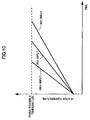
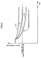
- FIGS. 10 through 13 are diagrams showing relationships between time and the heater temperature, that is, the surface temperature of the fixing roller 40, for different input voltages supplied from the commercial power supply to the main power supply unit 3.
- the voltage values of 90 V, 95 V and 100 V are merely examples and the voltage values are not limited to such, and the time base is shown in arbitrary units.
- FIG. 12 is a diagram showing a relationship between time and the heater temperature (the surface temperature of the fixing roller 40) for different input voltages of the main power supply unit 3 when starting the fixing unit 36 in a case where the power is supplied from the auxiliary power supply unit 4 to the auxiliary heater element 2b.
- FIG. 13 is a diagram showing a relationship between time and the heater temperature (the surface temperature of the fixing roller 40) for different input voltages of the main power supply unit 3 when the recording media P are successively supplied to the fixing unit 36 to carry out the image forming process continuously in a case where the power is supplied from the auxiliary power supply unit 4 to the auxiliary heater element 2b.
- the power from the auxiliary power supply unit 4 can be used in a power-ON state where the main power supply unit 3 is turned ON or, when the surface temperature of the fixing roller 40 (or the temperature of the fixing unit 36) is returned to the predetermined fixing temperature from the standby state (standby temperature), to thereby make it possible to reduce the time required to raise the surface temperature of the fixing roller 40 to the predetermined fixing temperature, as may be seen from FIGS. 10 and 12 .
- the controller 8 controls the switch 7 based on the temperature detection signal from the temperature sensor 51 so that the auxiliary power supply unit 4 is connected to the charger 6 and the auxiliary power supply unit 4 will not be used in the power-ON state or when the surface temperature of the fixing roller 40 (or the temperature of the fixing unit 36) is returned to the predetermined fixing temperature from the standby state (standby temperature).
- the controller 8 controls the switch 7 so that the auxiliary power supply unit 4 is connected to the auxiliary heater element 2b for the image forming process in the power-ON state or when the surface temperature of the fixing roller 40 (or the temperature of the fixing unit 36) is returned to the predetermined fixing temperature from the standby state (standby temperature).
- the controller 8 controls the switch 7 so as to supply a predetermined minimum power that can avoid deterioration of the productivity from the auxiliary power supply unit 4 to the auxiliary heater element 2b for the image forming process with respect to the consecutively supplied recording media P.
- the controller 8 controls the switch 7 so as to supply the remaining power of the auxiliary power supply unit 4 (power that remains after the discharge at the time of the image forming process with respect to the consecutively supplied recording media P) to the auxiliary heater element 2b in the power-ON state or when the surface temperature of the fixing roller 40 (or the temperature of the fixing unit 36) is returned to the predetermined fixing temperature from the standby state (standby temperature).
- the controller 8 controls the switch 7 so as to supply the remaining power of the auxiliary power supply unit 4 (power that remains after the discharge at the time of the image forming process with respect to the consecutively supplied recording media P) to the auxiliary heater element 2b in the power-ON state or when the surface temperature of the fixing roller 40 (or the temperature of the fixing unit 36) is returned to the predetermined fixing temperature from the standby state (standby temperature).
- the power stored in the auxiliary power supply unit 4 is used differently between the power-ON state or when the surface temperature of the fixing roller 40 (or the temperature of the fixing unit 36) is returned to the predetermined fixing temperature from the standby state (standby temperature) and when the image forming process is carried out with respect to the successively supplied recording media P, depending on the input voltage of the main power supply unit 3.
- the usage and the rate of usage of the power stored in the auxiliary power supply unit 4 is determined as shown in FIG.
- FIG. 14 is a diagram for explaining the usage and the rate of usage of the power stored in the auxiliary power supply unit 4.
- Timing T2 When carrying out the image forming process (by supplying the recording medium P to the fixing unit 36. It is effective to vary the supply timing and/or the supply amount depending on the number of recording media P to be subjected to the image forming process, the size of the recording medium P and the kind of the recording medium P,
- This standby state not only includes the normal standby state between jobs, but also the sleep mode and the power save mode of the image forming apparatus.
- the controller 8 controls the switch 7 based on the temperature detection signal from the temperature sensor 51 so that the auxiliary power supply unit 4 is connected to the charger 6 and the auxiliary power supply unit 4 will not be used in the power-ON state or when the surface temperature of the fixing roller 40 (or the temperature of the fixing unit 36) is returned to the predetermined fixing temperature from the standby state (standby temperature).
- the fixing unit (or heater) only a necessary amount of power from the auxiliary power supply unit is supplied to the fixing unit (or heater) depending on the usage, such as when raising the temperature of the fixing unit (or heater) to the predetermined fixing temperature and when carrying out the image forming process in response to the supplied recording medium, so as to reduce the time required to raise the temperature of the fixing unit (or heater) and to simultaneously avoid deterioration of the productivity.
- a method has been proposed to simultaneously supply the power from the main power supply unit and the power from the auxiliary power supply unit to the plurality of heater elements of the fixing unit, so as to reduce the waiting time that is required to raise the temperature of the fixing unit to a reload temperature, that is, the predetermined fixing temperature capable of carrying out the stable fixing process. By reducing this waiting time, it is also possible to reduce the total time required to form the image on the recording medium.
- the Japanese Laid-Open Patent Application No. 2002-174988 described above proposes such a method.
- a predetermined amount of heat needs to be applied on the recording medium P in order to fix the toner image, and thus, the supply of power to the main and auxiliary heater elements 193 and 194 is controlled so that the surface temperature of the fixing roller 191 reaches the reload temperature, that is, the predetermined fixing temperature capable of carrying out a stable fixing process.
- FIG. 26 is a circuit diagram showing a fixing unit system having a type of structure employed in this fourth embodiment.
- the main heater element 193 receives the power supplied from a main power supply unit 186, that is, an external power supply such as a commercial power supply.
- the auxiliary heater element 193 receives the power supplied from an auxiliary power supply unit 187 which is formed by a capacitor, for example.
- the auxiliary heater element 194 is desirably made up of a plurality of heater elements that are connected in parallel to the capacitor of the auxiliary power supply unit 187, so that at least one of these heater elements can be connected to the capacitor by controlling a switch part (not shown).
- all of the heater elements of the auxiliary heater element 194 are connected to the capacitor when starting the image forming apparatus, and one or more selected heater elements (less than the total number of heater elements) are connected to the capacitor when carrying out the image forming process by supplying the recording medium P to the fixing unit.
- the CPU 181 controls the supply of power via a triac 183 to the main heater element 193 via a controller 182, and controls the supply of power via a FET 185 to the auxiliary heater element 194 via a controller 184, based on the detection signals *1 and *2, so that the surface temperature of the fixing roller 191 reaches a set temperature.
- the capacitor of the auxiliary power supply unit 197 is connected to a charger 108a and becomes chargeable by controlling a switch 189.
- the charged voltage detector 188 is connected to the capacitor of the auxiliary power supply unit 187.
- FIG. 27 is a diagram for explaining an operation of the fixing unit system 190 shown in FIG. 26 .
- the fixing unit system 190 operates under the following preconditions when carrying out steps s81 through s83.
- Cpm conditions number of recording media P subjected to the image forming process (that is, number of copies made) per minute): 75 cpm
- Copy instruction Continuous copy instruction that instructs a continuous image forming process with respect to 100 successively supplied recording media
- Step s83 The supply of the recording media P at 75 cpm is started, and the power from the main power supply unit 186 is supplied to the main heater element 193 and the power from the auxiliary power supply unit 187 is supplied to the auxiliary heater element 194.
- the fixing roller 191 is heated by the heater elements 193 and 194, and the toner image (toner T) on each recording medium P is fixed as the recording media P successively pass through the nip part between the fixing roller 191 and the pressure roller 192.
- the amount of power supplied from the main power supply unit (commercial power supply) 186 is assumed to be constant (for example, 100 V and 15 A) and the amount of power to be supplied from the capacitor of the auxiliary power supply unit 187 is set by subtracting the amount of power supplied from the main power supply unit 186 from the amount of power required by the fixing unit, the voltage drop of the main power supply unit 186 caused insufficient heating of the fixing unit and resulted in the surface temperature of the fixing roller 191 becoming lower than the reload temperature.
- the main power supply unit 186 In addition, in recent office environments, not only the office automation (OA) equipments but also various electronic and electrical equipments such as personal computers receive the power supplied from the commercial power supply, that is, the main power supply unit 186. For this reason, it was found that the main power supply unit 186 cannot always supply constant power (100 V and 15 A). Furthermore, the extent of the voltage drop of the main power supply unit 186 is dependent on the electronic and electrical equipments used and varies for each office environment, thereby making it difficult to prevent the incomplete fixing in the image forming apparatus.
- the present inventors have found that the problems described above can be suppressed and the utilization efficiency of the capacitor of the auxiliary power supply unit can be improved, by monitoring an output voltage of the commercial power supply, that is, the main power supply unit.
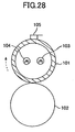
- FIG. 28 is a cross sectional view showing a fixing unit of the fourth embodiment.
- a known pressing mechanism or means urges a pressure roller 102 to press against a fixing roller 101 with a predetermined nip pressure, and the fixing roller 101 is rotated clockwise and the pressure roller 102 is rotated counterclockwise by a known driving mechanism or means (not shown).
- the fixing roller 101 and the pressure roller 102 are stationary when starting the fixing unit.
- the fixing roller 101 includes a main heater element 103 and an auxiliary heater element 104 which heat the fixing roller 101 so that the surface temperature of the fixing roller 101 reaches a predetermined fixing temperature capable of carrying out a fixing process with respect to a toner image (or toner T) that is formed on a recording medium P.
- the surface temperature of the fixing roller 101 is monitored by a temperature sensor 105.
- the temperature sensor 105 is arranged to monitor the surface temperature of the fixing roller 101 at a position on an opposite end from the nip part relative to a center axis of the fixing roller 101.
- the temperature sensor 105 may be formed by any type of sensor or detector, such as a radiation thermometer and a thermocouple, that can detect the surface temperature of the fixing roller 101, and may be a contact type which makes contact with the outer peripheral surface of the fixing roller 101 or a non-contact type.
- the fixing roller 101 is normally formed by a hollow cylindrical roller, but may be formed by an endless belt.
- the pressure roller 102 is normally formed by a hollow cylindrical roller having an outer surface that is made of a resilient material such as silicone rubber.
- FIG. 28 shows a case where the main and auxiliary heater elements 103 and 104 have a rod shape.
- the main heater element 103 generates heat when supplied with power from a main power supply unit 116 such as a commercial power supply capable of constantly supplying power.
- the fixing roller 101 is heated by the radiated heat from the main heater element 103.
- the auxiliary heater element 104 generates heat when supplied with power from an auxiliary power supply unit 117 such as a capacitor.
- the fixing roller 101 is heated by the radiated heat from the auxiliary heater element 104.
- the surface temperature of the fixing roller 101 is maintained to an appropriate temperature by turning the auxiliary power supply unit 117 ON and OFF by a power control unit or means.
- the recording medium P formed with the toner image (or toner T) is supplied to the nip part between the fixing roller 101 and the pressure roller 102.
- the toner image is fixed on the recording medium P as the recording medium P passes between the fixing roller 101 and the pressure roller 102 due to the heat and pressure applied on the recording medium P.
- FIG. 29 is a circuit diagram showing a fixing unit system of the fourth embodiment.
- the main heater element 103 receives the power supplied from the main power supply unit 116, that is, an external power supply such as the commercial power supply.
- the auxiliary heater element 103 receives the power supplied from an auxiliary power supply unit 117 which is formed by a capacitor, for example.
- the auxiliary heater element 104 is desirably made up of a plurality of heater elements that are connected in parallel to the capacitor of the auxiliary power supply unit 117, so that at least one of these heater elements can be connected to the capacitor by controlling a switch part (not shown).
- a charged voltage detector 118 detects a capacitor voltage of the capacitor, indicating the charged energy (remaining amount of power) of the auxiliary power supply unit 117, and outputs a voltage detection signal *1 indicative of the detected capacitor voltage.
- the temperature sensor 105 detects the surface temperature of the fixing roller 101, and outputs a temperature detection signal *2 indicative of the detected surface temperature.
- a voltage detector 101b detects the output voltage of the main power supply unit 116, and outputs a voltage detection signal *3 indicative of the detected output voltage of the main power supply unit 116.
- the detection signals *1, *2 and *3 are supplied to a controller that is formed by a CPU 111 directly, or via an input circuit (not shown).
- the CPU 111 controls the supply of power via a triac 113 to the main heater element 103 via a controller 112, and controls the supply of power via a FET 115 to the auxiliary heater element 104 via a controller 114, based on the detection signals *1, *2 and *3, so that the surface temperature of the fixing roller 101 reaches a set temperature.
- the capacitor of the auxiliary power supply unit 117 is connected to a charger 101a and becomes chargeable by controlling a switch 119.
- the charged voltage detector 118 is connected to the capacitor of the auxiliary power supply unit 117.
- the capacitor of the auxiliary power supply unit 117 has an electrostatic capacitance on the F order or greater, and may be realized by an electric double layer capacitor.
- FIG. 30 is a system block diagram showing an important part of the fixing unit system 110 of this fourth embodiment, related to changing a target voltage based on a voltage drop of the commercial power supply, that is, the main power supply unit 116.
- the CPU 111 shown in FIG. 30 includes an information analyzing part Dd and a control executing part Ca.
- This control executing part Ca includes a judging part 111C, a target voltage setting part 111e, and a charge and discharge control part 111A, as functional blocks.
- the judging part 111C has a function of judging whether or not a voltage drop of the main power supply unit (commercial power supply) 116 occurred based on the voltage detection signal *3, and judging whether or not the capacitor voltage of the auxiliary power supply unit 117 has reached a target voltage set in the target voltage setting part 111e based on the voltage detection signal *1.
- the judging part 111C holds a threshold value (commercial power supply voltage threshold value) for judging whether or not the voltage drop of the main power supply unit 116 occurred.
- the judging part 111C judges no voltage drop if the voltage detection signal *3 indicates that the output voltage of the main power supply unit 116 is greater than or equal to 93 V, and judges that the voltage drop occurred if the voltage detection signal *3 indicates that the output voltage of the main power supply unit 116 is less than 93 V.
- the charging and discharging voltage control part 111A has a function of controlling the charging of the capacitor of the auxiliary power supply unit 117 by controlling the switch 119 based on the judgement result of the judging part 111C related to the capacitor voltage of the auxiliary power supply unit 117. More particularly, the switch 119 is switched and connected to the auxiliary heater element 104 so as to put the capacitor of the auxiliary power supply unit 117 in the discharge standby state if the capacitor voltage is greater than or equal to the target voltage, and the switch 119 is switched and connected to the charger 101a so as to charge the capacitor of the auxiliary power supply unit 117 if the capacitor voltage is less than the target voltage.
- Step s11 When a voltage drop from 100 V to 92 V occurs in the output voltage of the main power supply unit (commercial power supply) 116, the voltage detection signal *3 from the voltage detector 101b indicating that the output voltage of the main power supply unit 116 has dropped to 92 V is input to the judging part 111C via the information analyzing part Dd within the CPU 111.
- Step s12 The judging part 111C judges that the voltage drop of the main power supply unit 116 has occurred since the voltage of 92 V indicated by the voltage detection signal *3 is less than the threshold value of 93 V.
- Step s14 The judging part 111C receives, via the information analyzing part Dd within the CPU 111, the voltage detection signal *1 from the charged voltage detector 118 indicating that the capacitor voltage is 40 V.
- Step s15 The judging part 111C judges that the capacitor voltage is less than the target voltage of 43 V, based on the voltage detection signal *1.
- Step s18 The judging part 111C judges that the capacitor voltage of the auxiliary power supply unit 117 is greater than or equal to the target voltage of 43 V, based on the voltage detection signal *1.
- Step s19 The charging and discharging voltage control part 111A switches and connects the switch 119 to the auxiliary heater element 104 so as to put the capacitor of the auxiliary power supply unit 117 in the discharge standby state, based on the judgement result of the judging part 111C indicating that the capacitor voltage is greater than or equal to the target voltage.
- Step s21 The supply of the recording media P at 75 cpm is started, and the power (92 V) from the main power supply unit 116 is supplied to the main heater element 103 and the power (discharge starting voltage of 43 V) from the auxiliary power supply unit 117 is supplied to the auxiliary heater element 104.
- the fixing roller 101 is heated by the heater elements 103 and 104, and the toner image (toner T) on each recording medium P is fixed as the recording media P successively pass through the nip part between the fixing roller 101 and the pressure roller 102.
- the surface temperature of the fixing roller 101 is maintained to the reload temperature or greater up to the last recording medium P, and a satisfactory fixing process can be carried out with respect to each of the successively supplied recording media P.
- the fixing process with respect to the 100 consecutive recording media P requires 80 seconds, for example.
- this fourth embodiment it is possible to carry out a satisfactory fixing process and maintain a high image quality of the images formed on the recording media P, even when the voltage drop of the main power supply unit 116 occurs, by effectively utilizing the capacitor of the auxiliary power supply unit 117.
- FIG. 32 is a cross sectional view showing the image forming apparatus of this fourth embodiment having the fixing unit system 110 described above.
- An image forming apparatus 400 shown in FIG. 32 employs the electrophotography technique and includes a drum-shaped photoconductive body 401 that is provided as an image bearing member, a charging unit 402 that uniformly charges the outer peripheral surface of the photoconductive body 401, a laser optical system 440 that irradiates a laser beam L on the charged surface of the photoconductive body 401 to expose and form an electrostatic latent image, and a developing unit 407.
- the developing unit 407 includes a developing sleeve 405 that develops the electrostatic latent image on the surface of the photoconductive body 401 into a toner image.
- the recording media P are supported on a plate 411 within the media supply cassette 410 which is detachable in a direction a.
- a spring urges the plate 111 upwards via an arm 412, so that the recording media P are pushed against a media supply roller 413.
- the top recording medium P is supplied from the media supply cassette 410 by the media supply roller 413 which rotates in response to an instruction from a controller (not shown), and a separating pad 414 prevents more than one recording medium P from being supplied at one time.
- the supplied recording medium P is transported to a resist roller pair 415.
- An operation panel 430 is provided in a slightly projecting manner on an upper front surface (top right portion in FIG. 32 ) of a housing 431.
- a media supply tray 432 is pivotally supported on the housing 431.
- the top recording medium P is supplied from the media supply tray 432 by a media supply roller 433 which rotates in response to an instruction from the controller (not shown), and a separating pad prevents more than one recording medium P from being supplied at one time.
- the supplied recording medium P is transported to the resist roller pair 415.
- the recording medium P is supplied from the selected one of the media supply cassette 410 and the media supply tray 432.
- the resist roller pair 415 transports the recording medium P towards the transfer unit 406 at a timing synchronized to the toner image on the photoconductive body 401.
- the transfer unit 406 transfers the toner image on the photoconductive body 401 onto the recording medium P supplied by the resist roller pair 514, and the fixing unit system 110 fixes the toner image on the recording medium P.
- each part of the image forming apparatus 400 is started, and thus, the fixing unit system 110 is also started at the same time.
- the supply of power from the capacitor of the auxiliary power supply unit 117 to the auxiliary heater element 104 is also started, to thereby heat the fixing roller 101 and put the fixing unit into the standby state.
- the power supply control of this fourth embodiment described above is carried out.
- the target voltage to which the capacitor of the auxiliary power supply unit 117 is to be charged is increased if the voltage drop occurs in the output voltage of the main power supply unit 116, so as to charge the capacitor to the target voltage.
- the recording medium P having the toner image that is fixed is ejected by an eject roller pair 420 onto an eject tray 422 via a media eject opening 421.
- the ejected recording media P are stacked on the eject tray 422.
- the eject tray 422 is provided with an auxiliary tray 425 which is slidable in a direction b.
- a power supply circuit 435, a printed circuit board 436 such as an engine driver board, a controller board 437 and various other electronic and control units are accommodated within a casing part 434.
- FIG. 33 is a cross sectional view showing a fixing unit having a type of structure employed in the first modification of the fourth embodiment.
- those parts which are the same as those corresponding parts in FIG. 25 are designated by the same reference numerals, and a description thereof will be omitted.
- the main heater element 193 and two auxiliary heater elements 194a and 194b are arranged at equi-angular intervals about a rotary axis within the fixing roller 191. Otherwise, the fixing unit shown in FIG. 33 is the same as the fixing unit shown in FIG. 25 .
- the main heater element 193 receives the power from the main power supply unit 186, that is, the commercial power supply, and has a rated power of 1200 W, for example.
- the auxiliary heater elements 194a and 194b receive the power from the auxiliary power supply unit 187, that is, the capacitor.
- the auxiliary heater element 194a is used when starting the image forming apparatus, and has a rated power of 700 W (at 100 V), for example.
- the auxiliary heater element 194b is used when supplying the recording medium P to the fixing unit, and has a rated power of 500 W (at 100 V), for example.
- the circuit structure of the fixing unit system including this fixing unit shown in FIG. 33 is basically the same as that shown in FIG. 26 , except that the auxiliary heater elements 194a and 194b are connected in parallel to the capacitor of the auxiliary power supply unit 187, so that at least one of these auxiliary heater elements 194a and 194b can be connected to the capacitor by controlling a switch part (not shown).
- the capacitor of the auxiliary power supply unit 187 is to be charged to a capacitor voltage of 100 V.
- Step s91 The capacitor of the auxiliary power supply unit 187 is charged to the target voltage of 100 V and is put in a discharge standby state.
- Step s92 When a continuous copy instruction is issued in response to the copy key (or button) of the operation part that is pushed by the user, for example, the operation of the fixing unit system 190 is started. More particularly, the power from the main power supply unit 186 is supplied to the main heater element 193, and the power from the capacitor of the auxiliary power supply unit 187 is supplied to the auxiliary heater elements 194a and 194b, so as to heat the fixing roller 191 to a temperature greater than or equal to the reload temperature. Since all of the heater elements 193, 194a and 194b are turned ON, a power of 2400 W is input to the fixing unit, to thereby rapidly heat the fixing roller 191 to the set temperature in 10 seconds.
- the present inventors have found that an incomplete fixing (or unstable fixing) may occur in some cases. According to analysis performed by the present inventors, it was found that the incomplete fixing is caused by a voltage drop of the main power supply unit 186.
- the amount of power supplied from the main power supply unit (commercial power supply) 186 is assumed to be constant (for example, 100 V) and the amount of power to be supplied from the capacitor of the auxiliary power supply unit 187 is set by subtracting the amount of power supplied from the main power supply unit 186 from the amount of power required by the fixing unit, the voltage drop of the main power supply unit 186 caused insufficient heating of the fixing unit and resulted in the surface temperature of the fixing roller 191 becoming lower than the reload temperature, even though the power from the main power supply unit 186 is supplied to the main heater element 193 and the power from the auxiliary power supply unit 187 is supplied to the auxiliary heater elements 194a and 194b.
- the main heater element 103 and two auxiliary heater elements 104a and 104b are arranged at equi-angular intervals about a rotary axis within the fixing roller 101. Otherwise, the fixing unit shown in FIG. 35 is the same as the fixing unit shown in FIG. 28 .
- the main heater element 103 receives the power from the main power supply unit 116, that is, the commercial power supply, and has a rated power of 1200 W, for example.
- the auxiliary heater elements 104a and 104b receive the power from the auxiliary power supply unit 117, that is, the capacitor.
- the auxiliary heater element 104a is used when starting the image forming apparatus, and has a rated power of 700 W (at 100 V), for example.
- the auxiliary heater element 104b is used when supplying the recording medium P to the fixing unit, and has a rated power of 500 W (at 100 V), for example.
- the circuit structure of the fixing unit system including this fixing unit shown in FIG. 35 is basically the same as that shown in FIG. 29 , except that the auxiliary heater elements 104a and 104b are connected in parallel to the capacitor of the auxiliary power supply unit 117, so that at least one of these auxiliary heater elements 104a and 104b can be connected to the capacitor by controlling a switch part 101C (shown in FIG. 36 ).
- the capacitor of the auxiliary power supply unit 117 is to be charged to a capacitor voltage of 100 V.
- FIG. 36 is a circuit diagram showing an important part of the fixing unit system of the first modification of the fourth embodiment, which differs from the fixing unit system shown in FIG. 29 .
- the auxiliary heater elements 104a and 104b are connected to the capacitor of the auxiliary power supply unit 117 via the switch part 101C, so that at least one of the auxiliary heater elements 104a and 104b may be selected to vary the total rated power of the heater part. More particularly, when a switch SW1 of the switch part 101C is turned ON and a switch SW2 of the switch part 101C is turned OFF, only the auxiliary heater element 104a is connected to the capacitor. When the switch SW1 is turned OFF and the switch SW2 is turned ON, only the auxiliary heater element 104b is connected to the capacitor. Further, when the switch SW1 is turned ON and the switch SW2 is turned ON, both the auxiliary heater elements 104a and 104b are connected to the capacitor.
- the information analyzing part Dd receives the voltage detection signal (or voltage information) *3 from the voltage detector 101b.
- the total rated power setting part 111f sets a normal combination of the heater elements 103, 104a and 104b, that is, the combination of the main heater element 103 and the auxiliary heater element 104b.
- the fixing unit system 110 operates under the following preconditions when carrying out steps s31 through s35.
- Cpm conditions number of recording media P subjected to the image forming process (that is, number of copies made) per minute): 75 cpm
- Capacitor charging target voltage 100 V
- Voltage drop of commercial power supply drop to 92 V from 100 V
- Capacitor voltage when copy instruction issued 100 V Heater rated power:
- Step s32 Since the output voltage (92 V) of the main power supply unit 116 is less than the threshold voltage (93 V), the judging part 111C judges that a voltage drop has occurred in the output voltage of the main power supply unit 116.
- Step s33 Based on the judgement result of the judging part 111C, the total rated power setting part 111f selects a combination of the main heater element 103 and the auxiliary heater element 104a to obtain the total rated power for the case where the recording media P are successively supplied for the continuous image forming process.
- Step s34 The operation of the fixing unit system 110 is started. More particularly, the power from the main power supply unit 116 is supplied to the main heater element 103, and the power from the capacitor of the auxiliary power supply unit 117 is supplied to the auxiliary heater elements 104a and 104b, so as to heat the fixing roller 101 to a temperature greater than or equal to the reload temperature. Since all of the heater elements 103, 104a and 104b are turned ON, a power of 2400 W is input to the fixing unit, to thereby rapidly heat the fixing roller 101 to the set temperature in 10 seconds.
- Step s35 The supply of the recording media P at 75 cpm is started, and the power from the main power supply unit 116 is supplied to the main heater element 103 and the power from the auxiliary power supply unit 117 is supplied to the auxiliary heater element 104a.
- the fixing roller 101 is heated by the heater elements 103 and 104a, and the toner image (toner T) on each recording medium P is fixed as the recording media P successively pass through the nip part between the fixing roller 101 and the pressure roller 102.
- the input power to the heater elements 103 and 104a is 1150 W in total.
- the surface temperature of the fixing roller 101 is maintained to the reload temperature or greater up to the last recording medium P, and a satisfactory fixing process can be carried out with respect to each of the successively supplied recording media P.
- this first modification of the example sets the total rated power for the case where the recording media are successively supplied for the continuous image forming process by using a combination of the main heater element and a selected one of the two auxiliary heater elements
- the heater element combination is of course not limited to such.
- One or a plurality of heater elements of the heater part may be selected to set the total rated power.
- the following combinations c1 through c4 are possible.
- Combination c1 Combination of the auxiliary heater elements 104a and 104b
- Combination c2 Combination of the main heater element 103 and the auxiliary heater element 104b
- Combination c3 Combination of the main heater element 103 and the auxiliary heater element 104a
- Combination c4 Combination of the main heater element 103 and the auxiliary heater elements 104a and 104b
- the image forming apparatus of this first modification of the example having the fixing unit system 110 described above is basically the same as the image forming apparatus 400 shown in FIG. 32 , and a detailed description thereof will be omitted.
- the image forming apparatus of this first modification of the third example receives an external copy instruction, the total rated power of the heater is set for the case where the recording media P are successively supplied for the continuous image forming process, depending on the output voltage of the main power supply unit (commercial power supply) 116 that is detected by the voltage detector 101b.
- the total rated power of the heater is changed to a value that is higher than normal when a voltage drop in the output voltage of the main power supply unit 116 is detected.
- the amount of heat generated by at least one of the auxiliary heater elements 104a and 104b powered by the capacitor of the auxiliary power supply unit 117 is increased so as to compensate for an amount corresponding to the voltage drop in the output voltage of the main power supply unit 116.
- FIG. 38 is a cross sectional view showing a fixing unit of a second modification of the fourth embodiment.
- a known pressing mechanism or means urges a pressure roller 102 to press against a fixing roller 101 with a predetermined nip pressure, and the fixing roller 101 is rotated clockwise and the pressure roller 102 is rotated counterclockwise by a known driving mechanism or means (not shown).
- the fixing roller 101 and the pressure roller 102 are stationary when starting the fixing unit.
- the fixing roller 101 includes a main heater element 103 and an auxiliary heater element 104 which heat the fixing roller 101 so that the surface temperature of the fixing roller 101 reaches a predetermined fixing temperature capable of carrying out a fixing process with respect to a toner image (or toner T) that is formed on a recording medium P.
- the surface temperature of the fixing roller 101 is monitored by a temperature sensor 105.
- the temperature sensor 105 is arranged to monitor the surface temperature of the fixing roller 101 at a position on an opposite end from the nip part relative to a center axis of the fixing roller 101.
- the temperature sensor 105 may be formed by any type of sensor or detector, such as a radiation thermometer and a thermocouple, that can detect the surface temperature of the fixing roller 101, and may be a contact type which makes contact with the outer peripheral surface of the fixing roller 101 or a non-contact type.
- the fixing roller 101 is normally formed by a hollow cylindrical roller, but may be formed by an endless belt.
- the pressure roller 102 is normally formed by a hollow cylindrical roller having an outer surface that is made of a resilient material such as silicone rubber.
- FIG. 38 shows a case where the main and auxiliary heater elements 103 and 104 have a rod shape.
- the main heater element 103 generates heat when supplied with power from a main power supply unit 116 such as a commercial power supply capable of constantly supplying power.
- the fixing roller 101 is heated by the radiated heat from the main heater element 103.
- the auxiliary heater element 104 generates heat when supplied with power from an auxiliary power supply unit 117 such as a capacitor.
- the fixing roller 101 is heated by the radiated heat from the auxiliary heater element 104.
- the surface temperature of the fixing roller 101 is maintained to an appropriate temperature by turning the auxiliary power supply unit 117 ON and OFF by a power control unit or means.
- the recording medium P formed with the toner image (or toner T) is supplied to the nip part between the fixing roller 101 and the pressure roller 102.
- the toner image is fixed on the recording medium P as the recording medium P passes between the fixing roller 101 and the pressure roller 102 due to the heat and pressure applied on the recording medium P.
- FIG. 39 is a circuit diagram showing a fixing unit system of this second modification of the fourth embodiment.
- the main heater element 103 receives the power supplied from the main power supply unit 116, that is, an external power supply such as the commercial power supply.
- the auxiliary heater element 103 receives the power supplied from an auxiliary power supply unit 117 which is formed by a capacitor, for example.
- the auxiliary heater element 104 is desirably made up of a plurality of heater elements that are connected in parallel to the capacitor of the auxiliary power supply unit 117, so that at least one of these heater elements can be connected to the capacitor by controlling a switch part (not shown).
- all of the heater elements of the auxiliary heater element 104 are connected to the capacitor when starting the image forming apparatus, and one or more selected heater elements (less than the total number of heater elements) are connected to the capacitor when carrying out the image forming process by supplying the recording medium P to the fixing unit.
- a charged voltage detector 118 detects a capacitor voltage of the capacitor, indicating the charged energy (remaining amount of power) of the auxiliary power supply unit 117, and outputs a voltage detection signal *1 indicative of the detected capacitor voltage.
- the temperature sensor 105 detects the surface temperature of the fixing roller 101, and outputs a temperature detection signal *2 indicative of the detected surface temperature.
- a voltage detector 101b detects the output voltage of the main power supply unit 116, and outputs a voltage detection signal *3 indicative of the detected output voltage of the main power supply unit 116.
- the detection signals *1, *2 and *3 are supplied to a controller that is formed by a CPU 131 directly, or via an input circuit (not shown).
- the CPU 131 controls the supply of power via a triac 113 to the main heater element 103 via a controller 112, and controls the supply of power via a FET 115 to the auxiliary heater element 104 via a controller 114, based on the detection signals *1, *2 and *3, so that the surface temperature of the fixing roller 101 reaches a set temperature.
- the capacitor of the auxiliary power supply unit 117 is connected to a charger 101a and becomes chargeable by controlling a switch 119.
- the charged voltage detector 118 is connected to the capacitor of the auxiliary power supply unit 117.
- the capacitor of the auxiliary power supply unit 117 has an electrostatic capacitance on the F order or greater, and may be realized by an electric double layer capacitor. It is desirable that the cell capacitance of the capacitor forming the auxiliary power supply unit 117 is 500 F or greater.
- FIG. 40 is a system block diagram showing an important part of the fixing unit system 130 of this second modification of the fourth embodiment, related to changing a target voltage based on a voltage drop of the commercial power supply, that is, the main power supply unit 116.
- the CPU 111 shown in FIG. 40 includes an information analyzing part Dd and a control executing part Ca.
- This control executing part Ca includes a judging part 131C and a charge and discharge control part 131A, as functional blocks.
- the information analyzing part Dd receives the voltage detection signal (or charged energy information) *1 from the charged voltage detector 118.
- the judging part 131C has a function of judging whether or not the capacitor voltage of the auxiliary power supply unit 117 has reached a target voltage to which the capacitor of the auxiliary power supply unit 117 is to be charged, based on the voltage detection signal *1.
- the judging part 131C holds a threshold value (target voltage threshold value) for judging whether or not the capacitor voltage of the auxiliary power supply unit 117 has reached the target voltage. It is desirable that this threshold value is set to approximately 80% of the cell rated voltage of the cells forming the capacitor.
- Step s41 The judging part 131C receives, via the information analyzing part Dd within the CPU 131, the voltage detection signal *1 from the charged voltage detector 118 indicating the capacitor voltage of the auxiliary power supply unit 117 is 35 V.
- Step s42 The judging part 131C judges that the capacitor voltage of the auxiliary power supply unit 117 indicated by the voltage detection signal *1 is less than the target voltage of 40 V.
- Step s43 The charging and discharging voltage control part 131A switches and connects the switch 119 to the charger 101a, based on the judgement result of the judging part 131C indicating that the capacitor voltage is less than the target voltage of 40 V, so as to start charging the capacitor of the auxiliary power supply unit 117.
- Step s44 When the capacitor voltage reaches 40 V, the judging part 131C receives, via the information analyzing part Dd within the CPU 131, the voltage detection signal *1 from the charged voltage detector 118 indicating that the capacitor voltage is 40 V.
- Step s45 The judging part 131C judges that the capacitor voltage of the auxiliary power supply unit 117 is greater than or equal to the target voltage of 40 V, based on the voltage detection signal *1.
- Step s46 The charging and discharging voltage control part 131A switches and connects the switch 119 to the auxiliary heater element 104 so as to put the capacitor of the auxiliary power supply unit 117 in the discharge standby state, based on the judgement result of the judging part 131C indicating that the capacitor voltage is greater than or equal to the target voltage of 40 V.
- the operation of the fixing unit system 130 is started. More particularly, when starting the fixing unit system 130 or when carrying out the continuous image forming process, the power from the main power supply unit 116 is supplied to the main heater element 103, and the power from the auxiliary power supply unit 117 is supplied to the auxiliary heater element 104.
- the fixing roller 101 is thus heated by the heater elements 103 and 104 to a temperature greater than or equal to the reload temperature, and the toner image (toner T) on each recording medium P is fixed as the recording media P successively pass through the nip part between the fixing roller 101 and the pressure roller 102.
- the surface temperature of the fixing roller 101 is maintained to the reload temperature or greater up to the last recording medium P, and a satisfactory fixing process can be carried out with respect to each of the successively supplied recording media P. Since the capacitor voltage of the auxiliary power supply unit 117 becomes less than the target voltage after the above discharge, the charging operation of the steps s41 through s46 is carried out again in the standby state of the fixing unit system 130.
Landscapes
- Physics & Mathematics (AREA)
- General Physics & Mathematics (AREA)
- Engineering & Computer Science (AREA)
- Microelectronics & Electronic Packaging (AREA)
- Fixing For Electrophotography (AREA)
- Control Or Security For Electrophotography (AREA)
Claims (15)
- Fixiereinheit (36), enthaltend:eine Heizung, die mit einer Hauptstromzuführeinheit betrieben wird, und eine aufladbare Hilfsstromzuführeinheit, und enthaltend ein Heizteil (1, 2), das ein Heizelement oder eine Mehrzahl von Heizelementen aufweist, ein Detektionsmittel, das eingerichtet ist bzw. die eingerichtet sind, Informationen zu detektieren, die sich auf das Heizteil (1, 2), und ein Steuermittel (8), das eingerichtet ist, die von der Hilfsstromzuführeinheit (4) dem Heizteil (1, 2) zugeführte Strommenge pro Einheitszeit abhängig von den von dem Detektionsmittel detektierten Informationen zu variieren; undein Fixierteil (40), das von dem Heizteil (1, 2) geheizt wird und eingerichtet ist, ein Bild auf einem Aufzeichnungsmedium zu fixieren, das in Gleitkontakt mit dem Heizteil (1, 2) steht oder nahe an dem Heizteil (1, 2) vorbeigehen,dadurch gekennzeichnet, dassdas Detektionsmittel eingerichtet ist, ein Zeitintervall zwischen einem vorhergehenden Auftrag und einem gegenwärtigen Auftrag für die Fixiereinheit (36) zu detektieren, und dass das Steuermittel (8) eingerichtet ist, die von der Hilfsstromzuführeinheit (4) dem Heizteil (1, 2) zugeführte Strommenge pro Einheitszeit abhängig von dem von dem Detektionsmittel detektierten Zeitintervall zu variieren.
- Fixiereinheit (36) wie in Anspruch 1 beansprucht, dadurch gekennzeichnet, dass
das Detektionsmittel eingerichtet ist, eine Anzahl von Aufzeichnungsmedien zu detektieren, die die Fixiereinheit (36) während eines vorhergehenden Auftrags passiert haben, und das Steuermittel (8) eingerichtet ist, die von der Hilfsstromzuführeinheit (4) dem Heizteil (1 ,2) zugeführte Strommenge pro Einheitszeit abhängig von der von dem Detektionsmittel für den vorhergehenden Auftrag detektierten Anzahl von Aufzeichnungsmedien zu variieren. - Fixiereinheit (36) wie in Anspruch 2 beansprucht, dadurch gekennzeichnet, dass das Steuermittel (8) eingerichtet ist, die von der Hilfsstromzuführeinheit (4) dem Heizteil (1, 2) zugeführte Strommenge pro Einheitszeit zu reduzieren, wenn die von dem Detektionsmittel detektierte Anzahl von Aufzeichnungsmedien größer als ein vorbestimmter Wert ist.
- Fixiereinheit (36) wie in Anspruch 1 beansprucht, dadurch gekennzeichnet, dass das Steuermittel (8) eingerichtet ist, die von der Hilfsstromzuführeinheit (4) dem Heizteil (1, 2) zugeführte Strommenge pro Einheitszeit zu reduzieren, wenn das von dem Detektionsmittel detektierte Zeitintervall kürzer als ein vorbestimmter Wert ist.
- Fixiereinheit (36) wie in Anspruch 1 beansprucht, dadurch gekennzeichnet, dass
das Detektionsmittel eingerichtet ist, eine Arbeitszeit der Fixiereinheit (36) zu während eine vorhergehenden Auftrags zu detektieren, und das Steuermittel (8) eingerichtet ist, die von der Hilfsstromzuführeinheit (4) dem Heizteil (1 ,2) zugeführte Strommenge pro Einheitszeit abhängig von der von dem Detektionsmittel für den vorhergehenden Auftrag detektierten Arbeitszeit zu variieren. - Fixiereinheit (36) wie in Anspruch 5 beansprucht, dadurch gekennzeichnet, dass das Steuermittel (8) eingerichtet ist, die von der Hilfsstromzuführeinheit (4) dem Heizteil (1, 2) zugeführte Strommenge pro Einheitszeit zu reduzieren, wenn die von dem Detektionsmittel detektierte Arbeitszeit länger als ein vorbestimmter Wert ist.
- Fixiereinheit (36) wie in Anspruch 1 beansprucht, dadurch gekennzeichnet, dass
das Heizteil (1, 2) ein Druckausübungsglied enthält, das Detektionsmittel eingerichtet ist, eine Temperatur des Druckausübungsglieds als die Informationen zu detektieren, und das Steuermittel (8) eingerichtet ist, die von der Hilfsstromzuführeinheit (4) dem Heizteil (1 ,2) zugeführte Strommenge pro Einheitszeit abhängig von der von dem Detektionsmittel detektierten Temperatur zu variieren. - Fixiereinheit (36) wie in Anspruch 1 beansprucht, dadurch gekennzeichnet, dass das Steuermittel (8) eingerichtet ist, die von der Hilfsstromzuführeinheit (4) dem Heizteil (1, 2) zugeführte Strommenge pro Einheitszeit zu reduzieren, wenn die von dem Detektionsmittel detektierte Temperatur des Druckausübungsglieds höher als ein vorbestimmter Wert ist.
- Fixiereinheit (36) wie in Anspruch 1 beansprucht, dadurch gekennzeichnet, dass das Steuermittel (8) eingerichtet ist, die von der Hilfsstromzuführeinheit (4) dem Heizteil (1, 2) zugeführte Strommenge pro Einheitszeit zu erhöhen, wenn die von dem Detektionsmittel detektierte Anzahl von Aufzeichnungsmedien kleiner als ein vorbestimmter Wert ist.
- Fixiereinheit (36) wie in Anspruch 1 beansprucht, dadurch gekennzeichnet, dass
das Detektionsmittel eingerichtet ist, eine Umgebungstemperatur des Heizteils (1, 2) Informationen zu detektieren, und das Steuermittel (8) eingerichtet ist, die von der Hilfsstromzuführeinheit (4) dem Heizteil (1 ,2) zugeführte Strommenge pro Einheitszeit abhängig von der von dem Detektionsmittel detektierten Umgebungstemperatur zu variieren. - Fixiereinheit (36) wie in Anspruch 10 beansprucht, dadurch gekennzeichnet, dass das Steuermittel (8) eingerichtet ist, die von der Hilfsstromzuführeinheit (4) dem Heizteil (1, 2) zugeführte Strommenge pro Einheitszeit zu reduzieren, wenn die von dem Detektionsmittel detektierte Umgebungstemperatur Druckausübungsglieds höher als ein vorbestimmter Wert ist.
- Fixiereinheit (36) wie in Anspruch 10 beansprucht, dadurch gekennzeichnet, dass das Steuermittel (8) eingerichtet ist, die von der Hilfsstromzuführeinheit (4) dem Heizteil (1, 2) zugeführte Strommenge pro Einheitszeit zu erhöhen, wenn die von dem Detektionsmittel detektierte Umgebungstemperatur geringer als ein vorbestimmter Wert ist.
- Fixiereinheit (36) wie in Anspruch 1 beansprucht, dadurch gekennzeichnet, dass die Hilfsstromzuführeinheit (4) einen Kondensator (C) enthält.
- Fixiereinheit (36) wie in Anspruch 13 beansprucht, dadurch gekennzeichnet, dass der Kondensator ein elektrischer Doppelschichtkondensator ist.
- Bilderzeugungsvorrichtung, umfassend:eine Fixiereinheit (46) gemäß irgendeinem der Ansprüche 1 bis 14.
Applications Claiming Priority (8)
| Application Number | Priority Date | Filing Date | Title |
|---|---|---|---|
| JP2003408710 | 2003-12-08 | ||
| JP2003408710A JP4470473B2 (ja) | 2003-12-08 | 2003-12-08 | 定着装置及びこの定着装置を用いた画像形成装置 |
| JP2004024794 | 2004-01-30 | ||
| JP2004024785A JP4252469B2 (ja) | 2004-01-30 | 2004-01-30 | 画像形成装置 |
| JP2004024794A JP4326975B2 (ja) | 2004-01-30 | 2004-01-30 | 画像形成装置 |
| JP2004024785 | 2004-01-30 | ||
| JP2004028834A JP4402972B2 (ja) | 2004-02-05 | 2004-02-05 | 画像形成装置 |
| JP2004028834 | 2004-02-05 |
Publications (3)
| Publication Number | Publication Date |
|---|---|
| EP1542092A2 EP1542092A2 (de) | 2005-06-15 |
| EP1542092A3 EP1542092A3 (de) | 2005-10-12 |
| EP1542092B1 true EP1542092B1 (de) | 2013-12-04 |
Family
ID=34528120
Family Applications (1)
| Application Number | Title | Priority Date | Filing Date |
|---|---|---|---|
| EP04029044.7A Expired - Lifetime EP1542092B1 (de) | 2003-12-08 | 2004-12-08 | Heizelement, Fixiereinheit und Bilderzeugungsgerät |
Country Status (2)
| Country | Link |
|---|---|
| US (4) | US7609988B2 (de) |
| EP (1) | EP1542092B1 (de) |
Families Citing this family (84)
| Publication number | Priority date | Publication date | Assignee | Title |
|---|---|---|---|---|
| US7609988B2 (en) * | 2003-12-08 | 2009-10-27 | Ricoh Company, Ltd. | Heater, fixing unit and image forming apparatus having power supplied from chargeable auxiliary power supplying unit varied per unit time |
| JP4578179B2 (ja) * | 2004-08-23 | 2010-11-10 | 株式会社リコー | 定着装置、及び画像形成装置 |
| JP4578178B2 (ja) * | 2004-08-23 | 2010-11-10 | 株式会社リコー | 画像形成装置 |
| JP4530770B2 (ja) * | 2004-09-08 | 2010-08-25 | 株式会社リコー | 定着装置、及び画像形成装置 |
| US7343113B2 (en) * | 2004-09-08 | 2008-03-11 | Ricoh Company, Ltd. | Fixing device, image forming apparatus including the fixing device, and fixing method |
| JP4530771B2 (ja) * | 2004-09-08 | 2010-08-25 | 株式会社リコー | 定着装置、及び画像形成装置 |
| US7333743B2 (en) * | 2004-09-09 | 2008-02-19 | Ricoh Company, Ltd. | Fixing device, image forming apparatus including the fixing device, and fixing method |
| JP2006154010A (ja) * | 2004-11-26 | 2006-06-15 | Ricoh Co Ltd | 定着装置及び画像形成装置 |
| JP4866031B2 (ja) * | 2005-04-22 | 2012-02-01 | 株式会社リコー | 画像形成装置 |
| JP2007035606A (ja) * | 2005-07-29 | 2007-02-08 | Ricoh Co Ltd | 加熱装置、定着装置及び画像形成装置 |
| US7933529B2 (en) * | 2005-08-30 | 2011-04-26 | Ricoh Company, Ltd. | Image forming apparatus, method for controlling image forming apparatus, fixing apparatus |
| JP4943100B2 (ja) * | 2005-09-16 | 2012-05-30 | 株式会社リコー | 画像形成装置 |
| JP5019814B2 (ja) * | 2005-10-14 | 2012-09-05 | 株式会社リコー | 画像形成装置および電力制御方法 |
| US8315534B2 (en) * | 2005-11-01 | 2012-11-20 | Ricoh Company, Ltd. | Image forming device to supply DC power to a load from both a main power supply device and a capacitor supply device |
| US7629780B2 (en) * | 2005-11-21 | 2009-12-08 | Ricoh Company, Ltd. | Power supply unit and printing apparatus with a supplemental power supply unit |
| JP4824396B2 (ja) | 2005-12-19 | 2011-11-30 | 株式会社リコー | 画像形成装置 |
| JP4793920B2 (ja) | 2006-02-24 | 2011-10-12 | 株式会社リコー | 電源装置および画像形成装置 |
| JP4577781B2 (ja) | 2006-03-03 | 2010-11-10 | 株式会社リコー | 電源装置および画像形成装置 |
| JP4917903B2 (ja) * | 2007-01-31 | 2012-04-18 | 株式会社リコー | 加熱装置、定着装置、加熱部材の温度制御方法及び画像形成装置 |
| US7855471B2 (en) * | 2007-03-15 | 2010-12-21 | Ricoh Company, Ltd. | Power supply device and image forming apparatus |
| JP4603027B2 (ja) * | 2007-11-08 | 2010-12-22 | 株式会社沖データ | 画像形成装置 |
| JP4592782B2 (ja) * | 2008-05-14 | 2010-12-08 | シャープ株式会社 | 定着装置及び画像形成装置 |
| JP5188278B2 (ja) * | 2008-06-10 | 2013-04-24 | キヤノン株式会社 | 電子機器 |
| JP5482104B2 (ja) | 2009-09-15 | 2014-04-23 | 株式会社リコー | 定着装置及び画像形成装置 |
| JP2011090232A (ja) * | 2009-10-26 | 2011-05-06 | Ricoh Co Ltd | 加熱装置、定着装置及び画像形成装置 |
| JP5648291B2 (ja) * | 2010-02-01 | 2015-01-07 | 株式会社リコー | 光沢付与装置および画像形成装置 |
| JP5482310B2 (ja) * | 2010-03-09 | 2014-05-07 | 株式会社リコー | 定着装置及び画像形成装置 |
| JP5640473B2 (ja) | 2010-06-04 | 2014-12-17 | 株式会社リコー | 定着装置及び画像形成装置 |
| JP5562132B2 (ja) * | 2010-06-14 | 2014-07-30 | キヤノン株式会社 | 加熱装置及び電圧検知回路 |
| JP5552939B2 (ja) | 2010-07-27 | 2014-07-16 | 株式会社リコー | ベルト走行装置、定着装置及び画像形成装置 |
| US20120036872A1 (en) * | 2010-08-10 | 2012-02-16 | Brent Alden Junge | Method and apparatus for improving energy efficiency of an ice maker system |
| JP5636889B2 (ja) | 2010-11-09 | 2014-12-10 | 株式会社リコー | 定着装置および画像形成装置 |
| JP5625779B2 (ja) | 2010-11-12 | 2014-11-19 | 株式会社リコー | 定着装置および画像形成装置 |
| JP5747502B2 (ja) | 2010-11-12 | 2015-07-15 | 株式会社リコー | 定着装置及び画像形成装置 |
| JP5696835B2 (ja) | 2010-12-14 | 2015-04-08 | 株式会社リコー | 定着装置及び画像形成装置 |
| JP5625860B2 (ja) | 2010-12-14 | 2014-11-19 | 株式会社リコー | 定着装置及び画像形成装置 |
| JP5625865B2 (ja) | 2010-12-16 | 2014-11-19 | 株式会社リコー | 定着装置及び画像形成装置 |
| US8693934B2 (en) | 2010-12-17 | 2014-04-08 | Ricoh Company, Ltd. | Fixing device and image forming apparatus incorporating same |
| JP5589820B2 (ja) | 2010-12-17 | 2014-09-17 | 株式会社リコー | 定着装置及び画像形成装置 |
| JP5640750B2 (ja) | 2011-01-07 | 2014-12-17 | 株式会社リコー | 定着装置、画像形成装置、定着制御方法 |
| JP5825545B2 (ja) | 2011-01-11 | 2015-12-02 | 株式会社リコー | 定着装置および画像形成装置 |
| JP5879988B2 (ja) | 2011-01-11 | 2016-03-08 | 株式会社リコー | 定着装置及び画像形成装置 |
| JP5669010B2 (ja) | 2011-01-11 | 2015-02-12 | 株式会社リコー | 定着装置及びその定着装置を備えた画像形成装置 |
| JP5699656B2 (ja) | 2011-02-08 | 2015-04-15 | 株式会社リコー | 光沢付与装置及び定着装置、画像形成装置 |
| JP2012181337A (ja) | 2011-03-01 | 2012-09-20 | Ricoh Co Ltd | 光沢付与装置及びこれを用いた画像形成装置 |
| JP2012185295A (ja) | 2011-03-04 | 2012-09-27 | Ricoh Co Ltd | 定着装置および画像形成装置 |
| JP5870569B2 (ja) | 2011-03-09 | 2016-03-01 | 株式会社リコー | 定着装置及び画像形成装置 |
| JP5768507B2 (ja) | 2011-03-17 | 2015-08-26 | 株式会社リコー | 定着装置および画像形成装置 |
| JP5708084B2 (ja) | 2011-03-17 | 2015-04-30 | 株式会社リコー | 定着装置、及び、これを備える画像形成装置 |
| JP5932249B2 (ja) * | 2011-06-14 | 2016-06-08 | キヤノン株式会社 | 画像形成装置 |
| JP5822061B2 (ja) | 2011-06-21 | 2015-11-24 | 株式会社リコー | 光沢付与装置、画像形成装置、カラー画像形成装置 |
| JP2013003517A (ja) | 2011-06-21 | 2013-01-07 | Ricoh Co Ltd | 光沢付与装置、定着装置、及び画像形成装置 |
| JP2013007801A (ja) | 2011-06-22 | 2013-01-10 | Ricoh Co Ltd | 光沢付与装置、及び画像形成装置 |
| JP5824903B2 (ja) | 2011-06-23 | 2015-12-02 | 株式会社リコー | 光沢付与装置および画像形成装置 |
| JP5831740B2 (ja) | 2011-06-30 | 2015-12-09 | 株式会社リコー | 定着装置、および画像形成装置 |
| JP5891764B2 (ja) | 2011-12-12 | 2016-03-23 | 株式会社リコー | 光沢付与装置および画像形成装置 |
| JP6136221B2 (ja) | 2011-12-27 | 2017-05-31 | 株式会社リコー | 定着装置、及び、画像形成装置 |
| JP6136220B2 (ja) | 2011-12-27 | 2017-05-31 | 株式会社リコー | 定着装置、及び、画像形成装置 |
| JP5796711B2 (ja) | 2011-12-28 | 2015-10-21 | 株式会社リコー | 定着装置及び画像形成装置 |
| JP2013140214A (ja) | 2011-12-28 | 2013-07-18 | Ricoh Co Ltd | 画像形成装置 |
| CN103186087B (zh) | 2011-12-28 | 2016-08-03 | 株式会社理光 | 定影装置、成像装置和分离构件 |
| JP5904325B2 (ja) | 2011-12-28 | 2016-04-13 | 株式会社リコー | 定着装置及び画像形成装置 |
| JP5970828B2 (ja) | 2012-01-19 | 2016-08-17 | 株式会社リコー | 分離部材、定着装置、及び画像形成装置 |
| JP5967468B2 (ja) | 2012-01-24 | 2016-08-10 | 株式会社リコー | 定着装置、及び、画像形成装置 |
| JP5943231B2 (ja) | 2012-01-26 | 2016-07-05 | 株式会社リコー | 定着装置、及び、画像形成装置 |
| JP6035668B2 (ja) | 2012-01-27 | 2016-11-30 | 株式会社リコー | 定着装置、及び、画像形成装置 |
| JP6051741B2 (ja) | 2012-01-31 | 2016-12-27 | 株式会社リコー | 定着装置および画像形成装置 |
| JP5751428B2 (ja) | 2012-01-31 | 2015-07-22 | 株式会社リコー | 定着装置及び画像形成装置 |
| JP5963105B2 (ja) | 2012-02-02 | 2016-08-03 | 株式会社リコー | 定着装置及び画像形成装置 |
| JP6423994B2 (ja) | 2012-02-09 | 2018-11-14 | 株式会社リコー | 定着装置及び画像形成装置 |
| JP5850326B2 (ja) | 2012-02-09 | 2016-02-03 | 株式会社リコー | 定着装置および画像形成装置 |
| JP6003619B2 (ja) | 2012-02-09 | 2016-10-05 | 株式会社リコー | 定着装置及び画像形成装置 |
| JP6201312B2 (ja) | 2012-02-09 | 2017-09-27 | 株式会社リコー | 画像形成装置 |
| JP6209311B2 (ja) | 2012-02-09 | 2017-10-04 | 株式会社リコー | 定着装置及び画像形成装置 |
| US9026024B2 (en) | 2012-02-09 | 2015-05-05 | Ricoh Company, Ltd. | Fixing device capable of minimizing damage of endless rotary body and image forming apparatus incorporating same |
| JP2013195857A (ja) | 2012-03-22 | 2013-09-30 | Ricoh Co Ltd | 定着装置、及び、画像形成装置 |
| JP6015176B2 (ja) | 2012-07-10 | 2016-10-26 | 株式会社リコー | 光沢付与装置、及び、画像形成装置 |
| JP6465578B2 (ja) * | 2013-08-07 | 2019-02-06 | キヤノン株式会社 | 画像形成装置 |
| JP6326829B2 (ja) * | 2014-01-28 | 2018-05-23 | 株式会社リコー | 電気機器及び残留電荷放電方法 |
| WO2016119896A1 (en) * | 2015-01-30 | 2016-08-04 | Hewlett-Packard Development Company, L.P. | Heating unit |
| US9715197B2 (en) * | 2015-07-09 | 2017-07-25 | Ricoh Company, Ltd. | Fixing device and image forming apparatus incorporating fixing device |
| JP6796274B2 (ja) | 2016-01-25 | 2020-12-09 | 株式会社リコー | 定着装置、及び画像形成装置 |
| JP7058965B2 (ja) * | 2017-09-29 | 2022-04-25 | キヤノン株式会社 | 定着装置 |
| JP7663861B2 (ja) | 2021-07-05 | 2025-04-17 | 株式会社リコー | 接離装置、定着装置及び画像形成装置 |
Family Cites Families (50)
| Publication number | Priority date | Publication date | Assignee | Title |
|---|---|---|---|---|
| JPS5773773A (en) | 1980-10-24 | 1982-05-08 | Ricoh Co Ltd | Method for warranting quality of copy of copier |
| JPS6017473B2 (ja) | 1982-08-03 | 1985-05-02 | 上村工業株式会社 | 乾式流動研摩用研摩材料 |
| JPS6017473A (ja) | 1983-07-09 | 1985-01-29 | Mita Ind Co Ltd | 熱定着装置の温度制御方法 |
| JPH0634133B2 (ja) * | 1984-11-21 | 1994-05-02 | 富士通株式会社 | フラッシュ定着装置 |
| US4771312A (en) * | 1985-02-15 | 1988-09-13 | Canon Kabushiki Kaisha | Image forming apparatus having a battery |
| JPS63113563A (ja) | 1986-10-31 | 1988-05-18 | Ricoh Co Ltd | 補助電源付き電子装置の読み書き制御装置 |
| JPS6459178A (en) * | 1987-08-31 | 1989-03-06 | Canon Kk | Battery state detecting apparatus |
| JPH0336579A (ja) | 1989-07-04 | 1991-02-18 | Canon Inc | 定着装置用の加熱装置 |
| JPH03174570A (ja) | 1989-12-04 | 1991-07-29 | Canon Inc | 画像形成装置 |
| US5481350A (en) * | 1993-04-12 | 1996-01-02 | Ricoh Company, Ltd. | Heat roller fixing device divided into first and second frames and with positioning members of the first frame |
| JP3118117B2 (ja) | 1993-06-01 | 2000-12-18 | 富士写真フイルム株式会社 | 定着用ヒーター制御装置 |
| US6055068A (en) * | 1994-05-09 | 2000-04-25 | Canon Kabushiki Kaisha | Facsimile apparatus with energy and ink conserving features |
| US5701554A (en) | 1994-06-10 | 1997-12-23 | Seiko Epson Corporation | Fixing apparatus having controller for setting a target temperature and for estimating the amount of heat transferred to a pressure roller |
| JPH09109518A (ja) * | 1995-10-19 | 1997-04-28 | Canon Inc | 電源制御装置および電子機器の電源制御方法 |
| JPH09230739A (ja) | 1996-02-22 | 1997-09-05 | Canon Inc | 画像形成方法および装置 |
| US5700994A (en) | 1996-04-01 | 1997-12-23 | Xerox Corporation | Apparatus and fuser control method for reducing power star fuser recovery time |
| JPH10282821A (ja) | 1997-04-03 | 1998-10-23 | Canon Inc | 画像形成装置および画像形成方法 |
| JP2000197277A (ja) | 1998-12-25 | 2000-07-14 | Asahi Glass Co Ltd | 電気二重層コンデンサ内蔵電源装置 |
| JP3588006B2 (ja) | 1999-05-06 | 2004-11-10 | 株式会社リコー | 画像形成装置 |
| JP2001324892A (ja) | 2000-05-17 | 2001-11-22 | Canon Inc | 像加熱装置及びそれを有する画像形成装置 |
| JP2002184554A (ja) | 2000-10-04 | 2002-06-28 | Ricoh Co Ltd | 加熱装置とそれを使用した定着装置及び画像形成装置 |
| US6542705B2 (en) * | 2000-09-29 | 2003-04-01 | Ricoh Company, Ltd. | Electrophotographic heating apparatus, system, and method |
| JP3670977B2 (ja) | 2000-09-29 | 2005-07-13 | 株式会社リコー | 定着装置 |
| US6701102B2 (en) * | 2000-12-01 | 2004-03-02 | Canon Kabushiki Kaisha | Method and apparatus for controlling the temperature in a fixing device of an image forming apparatus |
| JP2002280146A (ja) | 2001-03-15 | 2002-09-27 | Ricoh Co Ltd | 加熱装置、定着装置および画像形成装置 |
| JP4417611B2 (ja) | 2001-05-30 | 2010-02-17 | 株式会社リコー | 定着装置 |
| JP4365052B2 (ja) * | 2001-07-17 | 2009-11-18 | 株式会社リコー | 画像形成装置 |
| JP2003033003A (ja) | 2001-07-23 | 2003-01-31 | Fuji Xerox Co Ltd | ヒータ制御装置 |
| JP2003066764A (ja) | 2001-08-24 | 2003-03-05 | Fuji Xerox Co Ltd | 印刷装置、温度制御方法、およびプログラム |
| JP2003162184A (ja) * | 2001-11-26 | 2003-06-06 | Ricoh Co Ltd | 画像形成装置 |
| CN100355319C (zh) * | 2002-02-04 | 2007-12-12 | 株式会社理光 | 加热装置、定影装置及图像形成装置 |
| JP2003257590A (ja) | 2002-02-27 | 2003-09-12 | Ricoh Co Ltd | 加熱装置とそれを使用した定着装置及び画像形成装置 |
| US6813464B2 (en) * | 2002-03-01 | 2004-11-02 | Ricoh Company, Ltd. | Fixing device with a peeler and biasing devices and image forming apparatus including the same |
| JP3902565B2 (ja) * | 2002-05-31 | 2007-04-11 | 株式会社リコー | 定着装置および画像形成装置 |
| JP2004078155A (ja) | 2002-06-21 | 2004-03-11 | Ricoh Co Ltd | 画像形成装置 |
| WO2004008808A1 (ja) * | 2002-07-12 | 2004-01-22 | Ricoh Company, Ltd. | 加熱装置、補助電力供給装置、補助電力供給システム、定着装置及び画像形成装置 |
| JP2004070011A (ja) * | 2002-08-06 | 2004-03-04 | Ricoh Co Ltd | 定着装置、画像形成装置および定着制御方法 |
| JP2004117468A (ja) * | 2002-09-24 | 2004-04-15 | Ricoh Co Ltd | 画像形成装置 |
| US20040108309A1 (en) * | 2002-12-10 | 2004-06-10 | Xerox Corporation | Apparatus and fuser control method for reducing power star fuser recovery time |
| JP2004206079A (ja) * | 2002-12-13 | 2004-07-22 | Ricoh Co Ltd | 定着装置と画像形成装置 |
| US7054570B2 (en) * | 2003-03-27 | 2006-05-30 | Ricoh Company, Ltd. | Image-forming apparatus |
| JP4485833B2 (ja) * | 2003-04-10 | 2010-06-23 | 株式会社リコー | 定着装置、画像形成装置 |
| JP4531487B2 (ja) * | 2003-11-13 | 2010-08-25 | 株式会社リコー | 定着装置および画像形成装置 |
| US7609988B2 (en) * | 2003-12-08 | 2009-10-27 | Ricoh Company, Ltd. | Heater, fixing unit and image forming apparatus having power supplied from chargeable auxiliary power supplying unit varied per unit time |
| JP2005174577A (ja) | 2003-12-08 | 2005-06-30 | Ricoh Co Ltd | 加熱装置、これを用いた定着装置及びこの定着装置を用いた画像形成装置 |
| JP2005221676A (ja) * | 2004-02-04 | 2005-08-18 | Canon Inc | 画像形成装置およびその制御方法 |
| JP4386262B2 (ja) * | 2004-02-04 | 2009-12-16 | キヤノン株式会社 | 画像形成装置 |
| JP4418689B2 (ja) * | 2004-02-04 | 2010-02-17 | キヤノン株式会社 | 画像形成装置 |
| JP2005221677A (ja) * | 2004-02-04 | 2005-08-18 | Canon Inc | 画像形成装置 |
| JP2007035606A (ja) * | 2005-07-29 | 2007-02-08 | Ricoh Co Ltd | 加熱装置、定着装置及び画像形成装置 |
-
2004
- 2004-12-07 US US11/004,885 patent/US7609988B2/en not_active Expired - Fee Related
- 2004-12-08 EP EP04029044.7A patent/EP1542092B1/de not_active Expired - Lifetime
-
2009
- 2009-01-09 US US12/351,357 patent/US7664410B2/en not_active Expired - Fee Related
- 2009-09-01 US US12/552,080 patent/US7885569B2/en not_active Expired - Fee Related
-
2010
- 2010-12-17 US US12/971,321 patent/US7957663B2/en not_active Expired - Fee Related
Also Published As
| Publication number | Publication date |
|---|---|
| US20110085815A1 (en) | 2011-04-14 |
| EP1542092A3 (de) | 2005-10-12 |
| US7664410B2 (en) | 2010-02-16 |
| US7885569B2 (en) | 2011-02-08 |
| US7609988B2 (en) | 2009-10-27 |
| US7957663B2 (en) | 2011-06-07 |
| EP1542092A2 (de) | 2005-06-15 |
| US20050139584A1 (en) | 2005-06-30 |
| US20090317113A1 (en) | 2009-12-24 |
| US20090123172A1 (en) | 2009-05-14 |
Similar Documents
| Publication | Publication Date | Title |
|---|---|---|
| US7664410B2 (en) | Image forming apparatus with control of power to a fixing unit | |
| EP1542085B1 (de) | Heizvorrichtung mit haupt und neben Stromversorgungseinheit in einer Fixiervorrichtung für ein Bilderzeugungsgerät | |
| US7212759B2 (en) | Heating device, fixing device and image forming apparatus | |
| US7054570B2 (en) | Image-forming apparatus | |
| US7496309B2 (en) | Image forming apparatus with auxiliary power source | |
| JP2004070011A (ja) | 定着装置、画像形成装置および定着制御方法 | |
| JP4376082B2 (ja) | 定着装置及び画像形成装置 | |
| JP4789905B2 (ja) | 画像形成装置 | |
| JP4470473B2 (ja) | 定着装置及びこの定着装置を用いた画像形成装置 | |
| JP2006171089A (ja) | 画像形成装置 | |
| JP4402972B2 (ja) | 画像形成装置 | |
| JP2004303518A (ja) | 加熱装置、これを用いた定着装置及びこの定着装置を用いた画像形成装置 | |
| JP2005216785A (ja) | 加熱装置、定着装置及び画像形成装置 | |
| JP2004296166A (ja) | 加熱装置、これを用いた定着装置及びこの定着装置を用いた画像形成装置 | |
| JP5741905B2 (ja) | 画像形成装置 | |
| JP2002278355A (ja) | 定着装置 | |
| JP4473922B2 (ja) | 画像形成装置 | |
| JP4230344B2 (ja) | 画像形成装置 | |
| JP2004296152A (ja) | 加熱装置、これを用いた定着装置及びこの定着装置を用いた画像形成装置 | |
| JP2004319431A (ja) | 加熱装置、これを用いた定着装置及びこの定着装置を用いた画像形成装置 | |
| JP2005174576A (ja) | 加熱装置、これを用いた定着装置及びこの定着装置を用いた画像形成装置 | |
| JP5190816B2 (ja) | 画像形成装置 | |
| JP2005221742A (ja) | 画像形成装置 | |
| JP2004296292A (ja) | 加熱装置、これを用いた定着装置及びこの定着装置を用いた画像形成装置 | |
| JP2004296153A (ja) | 加熱装置、これを用いた定着装置及びこの定着装置を用いた画像形成装置 |
Legal Events
| Date | Code | Title | Description |
|---|---|---|---|
| PUAI | Public reference made under article 153(3) epc to a published international application that has entered the european phase |
Free format text: ORIGINAL CODE: 0009012 |
|
| 17P | Request for examination filed |
Effective date: 20041208 |
|
| AK | Designated contracting states |
Kind code of ref document: A2 Designated state(s): AT BE BG CH CY CZ DE DK EE ES FI FR GB GR HU IE IS IT LI LT LU MC NL PL PT RO SE SI SK TR |
|
| AX | Request for extension of the european patent |
Extension state: AL BA HR LV MK YU |
|
| PUAL | Search report despatched |
Free format text: ORIGINAL CODE: 0009013 |
|
| AK | Designated contracting states |
Kind code of ref document: A3 Designated state(s): AT BE BG CH CY CZ DE DK EE ES FI FR GB GR HU IE IS IT LI LT LU MC NL PL PT RO SE SI SK TR |
|
| AX | Request for extension of the european patent |
Extension state: AL BA HR LV MK YU |
|
| AKX | Designation fees paid |
Designated state(s): DE ES FR GB IT NL |
|
| 17Q | First examination report despatched |
Effective date: 20090518 |
|
| GRAP | Despatch of communication of intention to grant a patent |
Free format text: ORIGINAL CODE: EPIDOSNIGR1 |
|
| INTG | Intention to grant announced |
Effective date: 20130802 |
|
| GRAS | Grant fee paid |
Free format text: ORIGINAL CODE: EPIDOSNIGR3 |
|
| GRAA | (expected) grant |
Free format text: ORIGINAL CODE: 0009210 |
|
| AK | Designated contracting states |
Kind code of ref document: B1 Designated state(s): DE ES FR GB IT NL |
|
| REG | Reference to a national code |
Ref country code: GB Ref legal event code: FG4D |
|
| REG | Reference to a national code |
Ref country code: DE Ref legal event code: R096 Ref document number: 602004043918 Country of ref document: DE Effective date: 20140130 |
|
| REG | Reference to a national code |
Ref country code: NL Ref legal event code: VDEP Effective date: 20131204 |
|
| PG25 | Lapsed in a contracting state [announced via postgrant information from national office to epo] |
Ref country code: NL Free format text: LAPSE BECAUSE OF FAILURE TO SUBMIT A TRANSLATION OF THE DESCRIPTION OR TO PAY THE FEE WITHIN THE PRESCRIBED TIME-LIMIT Effective date: 20131204 |
|
| PG25 | Lapsed in a contracting state [announced via postgrant information from national office to epo] |
Ref country code: ES Free format text: LAPSE BECAUSE OF FAILURE TO SUBMIT A TRANSLATION OF THE DESCRIPTION OR TO PAY THE FEE WITHIN THE PRESCRIBED TIME-LIMIT Effective date: 20131204 |
|
| REG | Reference to a national code |
Ref country code: DE Ref legal event code: R097 Ref document number: 602004043918 Country of ref document: DE |
|
| PLBE | No opposition filed within time limit |
Free format text: ORIGINAL CODE: 0009261 |
|
| STAA | Information on the status of an ep patent application or granted ep patent |
Free format text: STATUS: NO OPPOSITION FILED WITHIN TIME LIMIT |
|
| 26N | No opposition filed |
Effective date: 20140905 |
|
| REG | Reference to a national code |
Ref country code: DE Ref legal event code: R097 Ref document number: 602004043918 Country of ref document: DE Effective date: 20140905 |
|
| PG25 | Lapsed in a contracting state [announced via postgrant information from national office to epo] |
Ref country code: IT Free format text: LAPSE BECAUSE OF FAILURE TO SUBMIT A TRANSLATION OF THE DESCRIPTION OR TO PAY THE FEE WITHIN THE PRESCRIBED TIME-LIMIT Effective date: 20131204 |
|
| REG | Reference to a national code |
Ref country code: FR Ref legal event code: PLFP Year of fee payment: 12 |
|
| REG | Reference to a national code |
Ref country code: FR Ref legal event code: PLFP Year of fee payment: 13 |
|
| PGFP | Annual fee paid to national office [announced via postgrant information from national office to epo] |
Ref country code: GB Payment date: 20161222 Year of fee payment: 13 |
|
| PGFP | Annual fee paid to national office [announced via postgrant information from national office to epo] |
Ref country code: FR Payment date: 20161222 Year of fee payment: 13 |
|
| GBPC | Gb: european patent ceased through non-payment of renewal fee |
Effective date: 20171208 |
|
| REG | Reference to a national code |
Ref country code: FR Ref legal event code: ST Effective date: 20180831 |
|
| PG25 | Lapsed in a contracting state [announced via postgrant information from national office to epo] |
Ref country code: FR Free format text: LAPSE BECAUSE OF NON-PAYMENT OF DUE FEES Effective date: 20180102 |
|
| PG25 | Lapsed in a contracting state [announced via postgrant information from national office to epo] |
Ref country code: GB Free format text: LAPSE BECAUSE OF NON-PAYMENT OF DUE FEES Effective date: 20171208 |
|
| P01 | Opt-out of the competence of the unified patent court (upc) registered |
Effective date: 20230522 |
|
| PGFP | Annual fee paid to national office [announced via postgrant information from national office to epo] |
Ref country code: DE Payment date: 20231214 Year of fee payment: 20 |
|
| REG | Reference to a national code |
Ref country code: DE Ref legal event code: R071 Ref document number: 602004043918 Country of ref document: DE |