EP1542477A2 - Dispositif d'affichage 2D/3D - Google Patents
Dispositif d'affichage 2D/3D Download PDFInfo
- Publication number
- EP1542477A2 EP1542477A2 EP04029386A EP04029386A EP1542477A2 EP 1542477 A2 EP1542477 A2 EP 1542477A2 EP 04029386 A EP04029386 A EP 04029386A EP 04029386 A EP04029386 A EP 04029386A EP 1542477 A2 EP1542477 A2 EP 1542477A2
- Authority
- EP
- European Patent Office
- Prior art keywords
- polarizing
- polarizing plate
- patterns
- display device
- plate
- Prior art date
- Legal status (The legal status is an assumption and is not a legal conclusion. Google has not performed a legal analysis and makes no representation as to the accuracy of the status listed.)
- Withdrawn
Links
Images


Classifications
-
- H—ELECTRICITY
- H04—ELECTRIC COMMUNICATION TECHNIQUE
- H04N—PICTORIAL COMMUNICATION, e.g. TELEVISION
- H04N13/00—Stereoscopic video systems; Multi-view video systems; Details thereof
- H04N13/30—Image reproducers
- H04N13/356—Image reproducers having separate monoscopic and stereoscopic modes
- H04N13/359—Switching between monoscopic and stereoscopic modes
-
- H—ELECTRICITY
- H04—ELECTRIC COMMUNICATION TECHNIQUE
- H04N—PICTORIAL COMMUNICATION, e.g. TELEVISION
- H04N13/00—Stereoscopic video systems; Multi-view video systems; Details thereof
- H04N13/30—Image reproducers
- H04N13/302—Image reproducers for viewing without the aid of special glasses, i.e. using autostereoscopic displays
- H04N13/31—Image reproducers for viewing without the aid of special glasses, i.e. using autostereoscopic displays using parallax barriers
Definitions
- the present invention relates to an electronic display device, and more particularly, to a display device that can selectively display 2D and 3D images.
- binocular parallax is used, and the method of displaying is stereoscopy, when glasses are required, and autostereoscopy, when no glasses are required.
- Stereoscopy can require the use of polarized glasses or liquid crystal shutter glasses.
- Autostereoscopy uses a lenticular display, a parallax barrier screen, or a parallax illumination.
- the stereoscopy is mainly use when many people are viewing, such as a theater using a polarized projector.
- autostereoscopy is mainly used when a small group of people are viewing such as for personal use, display for a game, a home TV set, an exhibition display, etc.
- FIG. 1 is a perspective view of a display device according to the parallax illumination method disclosed in U.S. Patent No. 4,717,949.
- the display device comprises a liquid crystal display 12 on which an image is displayed and an illumination plate 14, a front surface of which has a stationary barrier 16 having a plurality of slits 18 formed at a periodic interval on the back of the stationary barriers 16 are formed.
- the illumination plate 14 When light is emitted from a backlight mounted in the illumination plate 14, the illumination plate 14 becomes a backlight for 3D that irradiates light having stripe forms by passing through the plurality of slits 18 between the barriers 16. And, pixels of odd-numbered columns of the LCD 12 display a left eye image observed by the left eye and the pixels of even-numbered columns display right eye image observed by right eye thus obtaining a three dimensional image.
- This method can only display three dimensional images. Therefore, since movies with 3D contents are relatively rare, consumers cannot get much use out of this device. Accordingly, there is a need to develop a display device capable of switching back and forth from 2D to 3D images as required.
- FIG. 2 is a cross-sectional view of an autostereoscopic display disclosed in U.S. Patent No. 6,157,424, which is a typical display unit that can display both 2D and 3D images.
- the autostereoscopic display depicted in FIG. 2 has a structure that, instead of the stationary barriers 16 that include a plurality of slits, a liquid crystal shutter 10 is mounted behind the LCD 62.
- the backlight can be used selectively as a 2D backlight that generally irradiates light in uniform and a 3D backlight that irradiates light of stripe form spaced apart with a predetermined distance by regionally controlling the permeability distribution of light generated from a backlight by a liquid crystal shutter 10 using an electrical signal.
- the autostereoscopic display can easily alternate between 2D and 3D mode, however, a liquid crystal shutter 10 must be disposed behind the LCD 62. That is, two glass panels have to be used, thereby increasing the overall thickness of the LCD. Also, high power consumption is required to produce both 2D and 3D images.
- the present invention provides a display device that employs a pair of patterned polarizers in a stationary parallax illumination device combined with a 2D DISPLAY AND can switch between displaying 2D and 3D images by slightly moving polarizer parallel to each other.
- a display device that can display switching back and forth from 2D to 3D images selectively, comprising: a backlight unit; a liquid crystal device; and a light control device that includes a pair of polarizing plates, disposed between the backlight and the liquid crystal device, wherein each polarizing plate of the pair of the polarizing plates has polarizing patterns, and at least one of the pair of the polarizing plates is moveable.
- a display device for displaying 2D images including a backlight unit and a liquid crystal device, in which a light control device that includes a pair of polarizing plates each having a polarizing pattern are disposed in front of the liquid crystal device, and a parallax illumination occurs by moving one of the pair of polarizing plates.
- FIG. 3 is a cross-sectional view of a display device according to an embodiment of the present invention.
- the display device 100 comprises a backlight unit 102, a first polarizing plate 104, a second polarizing plate 106, and a thin film transistor liquid crystal device (TFT-LCD) 150.
- the LCD display device is not limited to using the TFT-LCD 150, and can include any transmissive display.
- FIG. 4 is a cross-sectional view of the TFT-LCD of FIG. 3.
- the TFT-LCD 150 comprises a first transparent substrate 154 a third polarizing plate 152 disposed on a surface of the first transparent substrate 154, a transparent electrode 156 disposed on the other surface of the first transparent substrate 154, a liquid crystal unit 158 formed on the transparent electrode 156, a patterned transparent electrode 160 facing the transparent electrode 156 in the liquid crystal unit 158, a second transparent substrate 162 formed on the patterned transparent electrode 160, and a frontal polarizing plate 164 formed on the second transparent substrate 162.
- the first and the second transparent substrate 154 and 162 may be formed of glass or polymer, and the transparent electrode 156 and the patterned transparent electrode 160 may both be formed of Indium-Tin-Oxide (ITO).
- ITO Indium-Tin-Oxide
- the polarizing plates can be formed by absorbing iodine or a bicolor dye on a patterned vertical alignment (PVA) film which is a polymer elongated to one direction.
- PVA patterned vertical alignment
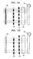
- FIGS. 5A and 5B are cross-sectional views for describing an operation of the display when a pair of linear polarizing plates is disposed in front of the TFT-LCD.
- the black colored regions of the pair of linear polarizing plates represents 90° polarizing patterns
- that of the white region represents 0° polarizing patterns.
- the frontal polarizing plate 164 is a 45° polarizing plate and the third polarizing plate 152 is a 135° polarizing plate, and each of the first and the second polarizing plates 104 and 106 has an alternating 0° and 90° polarizing patterns.
- the 45° polarized light passes through the 0° polarizing patterns and the 90° polarizing patterns of the first polarizing plate 104. Accordingly, the light passed through the first polarizing plate 104 has stripe form portions of 0° polarized light and stripe form portions of 90° polarized light, alternately disposed. Intensities of the 0° polarized light and the 90° polarized light are equal.
- the second polarizing plate 106 has the same polarizing pattern as the first polarizing pattern 104.
- the size of the 0° and 90° polarizing patterns of the second polarizing plate 106 may be different from each other.
- Phases of the polarizing patterns of the first polarizing plate 104 and those of the second polarizing plate 106 can be placed in a non-aligned manner by slightly moving one of the first polarizing plate 104 and the second polarizing plate 106 parallel to each other.
- the non-aligned state is shown in FIG. 5A.
- the 0° polarized light exiting from the first polarizing plate 104 cannot pass through the 90° polarizing patterns but can pass through the 0° polarizing patterns of the second polarizing plate 106, and the 90° polarized light exiting from the first polarizing plate 104 cannot pass through the 0° polarizing patterns but can pass through the 90° polarizing patterns of the second polarizing plate 106, Thus, a light pattern 130 exits second polarizing plate 106.
- the pair of polarizing plates 104 and 106 act as a 3 D barrier through which light having a line-shaped pattern passes so that a left eye and a right eye observe separate images.
- a 3D effect can be obtained by generating a left image for observation by a viewer's left eye in odd-numbered columns of the TFT-LCD 150 and generating a right image for observation by the viewer's right eye in even-numbered columns of the TFT-LCD 150.
- the patterns of the first and the second polarizing plates 104 and 106 are aligned by slightly moving one of the first polarizing plate 104 and the second polarizing plate 106 parallel to the other such that the light passing through the of 0° polarizing patterns of the first polarizing plate 104 can pass through the 0° polarizing patterns of the second polarizing plate 106, and the light passing through the 90° polarizing patterns of the first polarizing plate 104 can pass through the 90° polarizing patterns of the second polarizing plate 106,
- the light passed through the pair of polarizing plates 104 and 106 can be observed as a 2D image in which the left eye and right eye see the same image, that is, this becomes an ordinary 2D image display device,
- a light pattern 132 exits second polarizing plate 106.
- FIG. 6 is a cross-sectional view for describing an operation of the display device when the pair of linear polarizing plates is disposed between the TFT-LCD and the backlight unit.
- the display device in FIG. 6 has the same operational principle as the display device depicted in FIGS. 5A and 5B, with the only difference being that the pair of patterned polarizing plates 104 and 106 are disposed between the TFT-LCD 150 and the backlight unit 102.
- the two patterned polarizing plates i.e., the first and the second polarizing plates 104 and 106
- the pair of patterned polarizing plates 104 and 106 are disposed between the backlight unit 102 and the TFT-LCD 150 to act as the 3D image display parallax barrier. Accordingly, the device depicted in FIG.
- FIG. 6 is a switching device that changes a type of a backlight between one used for viewing 2D image and one used for 3D image by slightly moving the first polarizing plate 104 that is closer to the backlight unit 102. Also, the same effect can be obtained by slightly moving the second polarizing plate 106 parallel to the first polarizing plate 104.
- the principle of the display of FIG. 6 is the same principle as explained with reference to the FIGS. 5A and 5B. That is, light that has passed through the 0° polarizing patterns of each of the first polarizing plate 104 and the second polarizing plate 106, and light that has passed through the 90° polarizing patterns of each of the first polarizing plate 104 and the second polarizing plate 106 can enter the TFT-LCD 150, while light that has passed through the 0° polarizing patterns of the first polarizing plate 104 does not pass through the 90° polarizing patterns of the second polarizing plate 106, and light that has passed through the 90° polarizing patterns of the first polarizing plate 104 cannot pass through the 0° polarizing patterns of the second polarizing plate 106.
- the light that has passed through the first and the second polarizing plates 104 and 106 enters the third polarizing plate 152, which is polarized in 135° disposed at the front of the TFT-LCD 150 with a uniform intensity.
- a light pattern 134 exits the TFT-LCD 150,
- a 3D image can be observed by crossing the patterns of the two polarizing plates 104 and 106 by slightly moving the first and/or the second polarizing plates 104 and 106.
- 2D images can be observed by supplying a pattern for 2D images to the TFT-LCD 150 by aligning the two polarizing patterns of the first and the second polarizing plates 104 and 106.
- the display device 100 enables selectively switching between 2D and 3D modes by slightly moving the first and the second polarizing plates 104 and 106 with respect to each other in parallel.
- FIGS. 7A and 7B are cross-sectional views for describing an operation of a display device according to an embodiment of the present invention.
- a black colored region of a pair of linear polarizing plates 204 and 206 represents a 135° polarizing pattern
- a white colored region represents 45° polarizing pattern.
- the present embodiment depicted in FIGS. 7A and 7B is different from the embodiment depicted in FIGS. 5A and 5B in that the pair of the first and the second polarizing plates 204 and 206 have stripe form patterns of 135°and 45° polarizing alternating patterns.
- non-polarized light emitted from the backlight unit 202 becomes polarized light having 45° polarized and 135° polarized stripe form portions.
- the 135° polarized light exiting from the first polarizing plate 204 cannot pass through the 45° polarizing patterns of the second polarizing plate 206 but can pass through the 135° polarizing patterns, and the 45° polarized light exiting from the first polarizing plate 204 cannot pass through the 135° polarizing patterns of the second polarizing plate 206, but can pass through the 45° polarizing patterns of the second polarized plate 206.
- the light that passes through the second polarizing plate 206 enters a A /4 plate 224.
- a 135° polarized portion of light becomes left circularly polarized and a 45 ° polarized portion of the light becomes right circularly polarized when passing the ⁇ /4 plate 224.
- Both the left and right circularly polarized lights exiting from the ⁇ /4 plate 224 pass through the third polarizing plate 152 of the TFT-LCD 150 which is a 135° polarizing plate. If there is no ⁇ /4 plate 224 between the second polarizing plate 206 and the TFT-LCD 150, the 45 ° polarized portion of the light would be blocked by the third polarizing plate 152.
- the left circularly polarized light and the right circularly polarized light form a regularly spaced pattern 135 such that the left eye and the right eye see different images. This is done by slightly moving the first polarizing plate 204 in parallel with the second polarizing plate 206 and fixing the second polarizing plate 206 in place.
- the light that passes through the 45° polarized regions of both the first and the second polarizing plates 204 and 206 is transformed into a left circularly polarized light by the A /4 plate 224, and the light that passes through the 135° polarizing patterns of both the first and the second polarizing plates 204 and 206 is transformed into right circularly polarized light by the A /4 plate 224.
- the left circularly polarized light and the right circularly polarized light exiting from the A /4 plate 224 are cast on a rear surface of the TFT-LCD 150, and the intensity of light passing through the third polarizing plate 152, which is 135° polarized, are uniform.
- the light pattern 136 that has passed through the pair of non-polarizing plate 204 and 206 forms 2D images by allowing a left eye and a right eye to see identical images.
- a width of a light valve through which light used for viewing 3D images passes can be easily controlled by moving the patterned micro polarizing plate.
- FIG. 8 is a cross-sectional view for describing an operation principle of a display device according to an embodiment of the present invention.
- the present embodiment depicted in FIG. 8 is substantially same as the embodiment depicted in FIGS. 7A and 7B except that the TFT-LCD 150, the A /4 plate 224 and the second polarizing plate 206 are separated one another, Therefore the principle of the display of FIG. 8 is the same principle as explained with reference to the FIGS. 7A and 7B.
- the resulting light pattern 138 can be 2D or 3D images depending on the alignment of the first and second polarizing plates 204 and 206.
- a display device allows a viewer to switch between 2D and 3D images by slightly moving one of a pair of polarizing plates, each having polarized regions forming columns, and the width of light valve through which light passes when displaying a 3D image can be easily controlled.
- a display device is capable of displaying both 2D and 3D images without requiring continuous power consumption when viewing 3D images since the device does not use a liquid crystal shutter.
Landscapes
- Engineering & Computer Science (AREA)
- Multimedia (AREA)
- Signal Processing (AREA)
- Liquid Crystal (AREA)
- Polarising Elements (AREA)
- Testing, Inspecting, Measuring Of Stereoscopic Televisions And Televisions (AREA)
Applications Claiming Priority (2)
| Application Number | Priority Date | Filing Date | Title |
|---|---|---|---|
| KR2003089356 | 2003-12-10 | ||
| KR1020030089356A KR100580633B1 (ko) | 2003-12-10 | 2003-12-10 | 디스플레이 디바이스 |
Publications (2)
| Publication Number | Publication Date |
|---|---|
| EP1542477A2 true EP1542477A2 (fr) | 2005-06-15 |
| EP1542477A3 EP1542477A3 (fr) | 2008-01-23 |
Family
ID=34511199
Family Applications (1)
| Application Number | Title | Priority Date | Filing Date |
|---|---|---|---|
| EP04029386A Withdrawn EP1542477A3 (fr) | 2003-12-10 | 2004-12-10 | Dispositif d'affichage 2D/3D |
Country Status (4)
| Country | Link |
|---|---|
| US (2) | US7250990B2 (fr) |
| EP (1) | EP1542477A3 (fr) |
| JP (1) | JP3899099B2 (fr) |
| KR (1) | KR100580633B1 (fr) |
Cited By (3)
| Publication number | Priority date | Publication date | Assignee | Title |
|---|---|---|---|---|
| EP1711022A3 (fr) * | 2005-04-04 | 2010-01-20 | Samsung Electronics Co., Ltd. | Dispositif d'affichage stéréoscopique avec commutation entre des modes de fonctionnement 3D et 2D en utilisant une grille de diffraction de polarisation |
| CN101876755B (zh) * | 2010-02-05 | 2011-12-07 | 华映视讯(吴江)有限公司 | 一种立体显示器 |
| WO2013007036A1 (fr) * | 2011-07-13 | 2013-01-17 | 惠州市睿立宝莱光电科技有限公司 | Modulateur de lumière à cristaux liquides permettant de convertir un signal lumineux en une imagerie stéréo à polarisation circulaire bidirectionnelle |
Families Citing this family (27)
| Publication number | Priority date | Publication date | Assignee | Title |
|---|---|---|---|---|
| US7564504B2 (en) * | 2002-11-29 | 2009-07-21 | Asahi Glass Company, Limited | Phase plate and an optical data recording/reproducing device |
| GB0328005D0 (en) * | 2003-12-03 | 2004-01-07 | Koninkl Philips Electronics Nv | 2D/3D Displays |
| KR101113235B1 (ko) * | 2004-11-29 | 2012-02-29 | 삼성전자주식회사 | 입체 디스플레이 장치 |
| TWI264600B (en) * | 2005-02-03 | 2006-10-21 | Au Optronics Corp | 2D/3D display and method for forming 3D images |
| KR100922348B1 (ko) * | 2005-08-29 | 2009-10-21 | 삼성모바일디스플레이주식회사 | 입체 영상 표시장치 |
| KR101167318B1 (ko) * | 2005-08-31 | 2012-07-19 | 엘지디스플레이 주식회사 | 입체 영상 표시 장치 |
| KR101331900B1 (ko) * | 2006-06-29 | 2014-01-14 | 엘지디스플레이 주식회사 | 광제어필름을 이용한 입체영상 표시장치 |
| KR101309313B1 (ko) * | 2006-06-30 | 2013-09-13 | 엘지디스플레이 주식회사 | 화면이 분할된 입체영상 표시장치 |
| KR20080079550A (ko) * | 2007-02-27 | 2008-09-01 | 삼성전자주식회사 | 2차원/3차원 영상 호환용 고효율 디스플레이 장치 |
| KR100839414B1 (ko) * | 2007-04-19 | 2008-06-19 | 삼성에스디아이 주식회사 | 전자 영상 기기 |
| KR101406795B1 (ko) * | 2007-05-30 | 2014-06-12 | 삼성전자주식회사 | 스캐닝이 가능한 백라이트를 이용한 풀해상도의2차원/3차원 영상 디스플레이 장치 및 제어 방법 |
| JP5165443B2 (ja) | 2007-06-14 | 2013-03-21 | 株式会社フジクラ | 石英系マルチコア光ファイバ |
| JP2009069458A (ja) * | 2007-09-13 | 2009-04-02 | Seiko Epson Corp | 電気光学装置及び電子機器 |
| BRPI0910144A2 (pt) * | 2008-06-27 | 2016-07-05 | Koninkl Philips Electronics Nv | dispositivo de display autoestereoscópico e método de formação de imagens autoestereoscópico |
| KR101277223B1 (ko) * | 2008-07-09 | 2013-06-24 | 엘지디스플레이 주식회사 | 입체영상표시장치 |
| US7815729B2 (en) * | 2009-03-05 | 2010-10-19 | Cummings Robert S | Method for recycling construction and demolition fines |
| US7978407B1 (en) | 2009-06-27 | 2011-07-12 | Holovisions LLC | Holovision (TM) 3D imaging with rotating light-emitting members |
| JP4875127B2 (ja) * | 2009-09-28 | 2012-02-15 | パナソニック株式会社 | 三次元画像処理装置 |
| US9106925B2 (en) * | 2010-01-11 | 2015-08-11 | Ubiquity Holdings, Inc. | WEAV video compression system |
| JP4818440B2 (ja) * | 2010-01-21 | 2011-11-16 | 株式会社東芝 | 映像表示装置及び映像表示方法 |
| US8587498B2 (en) * | 2010-03-01 | 2013-11-19 | Holovisions LLC | 3D image display with binocular disparity and motion parallax |
| JP2012002866A (ja) * | 2010-06-14 | 2012-01-05 | Sony Corp | 立体表示用光学デバイスおよび立体表示装置 |
| JP2012053342A (ja) * | 2010-09-02 | 2012-03-15 | Sony Corp | 表示装置 |
| JP5664031B2 (ja) * | 2010-09-02 | 2015-02-04 | ソニー株式会社 | 表示装置 |
| KR101296910B1 (ko) * | 2010-10-20 | 2013-08-14 | 엘지디스플레이 주식회사 | 게이트 드라이버 및 이를 포함한 유기발광다이오드 표시장치 |
| CN105304677B (zh) * | 2015-09-24 | 2019-09-06 | 京东方科技集团股份有限公司 | 一种oled显示面板及显示装置、显示系统 |
| CN105467604B (zh) | 2016-02-16 | 2018-01-12 | 京东方科技集团股份有限公司 | 一种3d显示装置及其驱动方法 |
Family Cites Families (19)
| Publication number | Priority date | Publication date | Assignee | Title |
|---|---|---|---|---|
| JPS5132110B2 (fr) | 1972-07-19 | 1976-09-10 | ||
| JPS5327661A (en) | 1976-08-04 | 1978-03-15 | Unitika Ltd | Method of producing biaxially stretching polyvinyl alcohol film excellent in moistureeproof and heat seal property |
| JPH0785138B2 (ja) * | 1986-05-29 | 1995-09-13 | 日本電装株式会社 | 光透過量調整装置 |
| JP2526652B2 (ja) | 1989-01-05 | 1996-08-21 | 日本電気株式会社 | 液晶投射型立体表示装置 |
| EP0610924B1 (fr) * | 1993-02-10 | 2001-10-10 | Stanley Electric Co., Ltd. | Dispositif d'affichage à cristal liquide avec structure à multi-domaines |
| JP2778543B2 (ja) * | 1995-07-27 | 1998-07-23 | 日本電気株式会社 | 立体表示装置 |
| JPH09304739A (ja) * | 1996-05-17 | 1997-11-28 | Canon Inc | 立体画像表示方法及びそれを用いた立体画像表示装置 |
| US6046849A (en) * | 1996-09-12 | 2000-04-04 | Sharp Kabushiki Kaisha | Parallax barrier, display, passive polarisation modulating optical element and method of making such an element |
| GB2317291A (en) | 1996-09-12 | 1998-03-18 | Sharp Kk | Observer tracking directional display |
| JP2882393B2 (ja) * | 1997-01-27 | 1999-04-12 | 日本電気株式会社 | 立体表示装置 |
| US6157424A (en) * | 1998-03-30 | 2000-12-05 | Dimension Technologies, Inc. | 2D/3D imaging display |
| JPH11334877A (ja) * | 1998-05-22 | 1999-12-07 | Sekisui Chem Co Ltd | 長尺物の積み上げ装置 |
| US6590605B1 (en) * | 1998-10-14 | 2003-07-08 | Dimension Technologies, Inc. | Autostereoscopic display |
| JP2001045521A (ja) | 1999-07-30 | 2001-02-16 | Canon Inc | 立体画像撮影光学系及びそれを用いた立体画像撮影装置 |
| GB0119176D0 (en) * | 2001-08-06 | 2001-09-26 | Ocuity Ltd | Optical switching apparatus |
| JP2003066370A (ja) * | 2001-08-27 | 2003-03-05 | Canon Inc | 立体ディスプレイ装置 |
| JP3932098B2 (ja) * | 2002-01-31 | 2007-06-20 | 株式会社デンソー | 車両用配電装置およびユーザー後付け負荷接続用の補助端子 |
| JP2003337390A (ja) * | 2002-05-17 | 2003-11-28 | Canon Inc | 画像表示装置および画像表示システム |
| GB2393344A (en) * | 2002-09-17 | 2004-03-24 | Sharp Kk | Autostereoscopic display |
-
2003
- 2003-12-10 KR KR1020030089356A patent/KR100580633B1/ko not_active Expired - Fee Related
-
2004
- 2004-12-10 JP JP2004358498A patent/JP3899099B2/ja not_active Expired - Fee Related
- 2004-12-10 US US11/008,128 patent/US7250990B2/en not_active Expired - Lifetime
- 2004-12-10 EP EP04029386A patent/EP1542477A3/fr not_active Withdrawn
-
2007
- 2007-05-09 US US11/746,336 patent/US7382425B2/en not_active Expired - Lifetime
Cited By (4)
| Publication number | Priority date | Publication date | Assignee | Title |
|---|---|---|---|---|
| EP1711022A3 (fr) * | 2005-04-04 | 2010-01-20 | Samsung Electronics Co., Ltd. | Dispositif d'affichage stéréoscopique avec commutation entre des modes de fonctionnement 3D et 2D en utilisant une grille de diffraction de polarisation |
| US7697203B2 (en) | 2005-04-04 | 2010-04-13 | Samsung Electronics Co., Ltd. | Stereoscopic display switching between 2D/3D images using polarization grating screen |
| CN101876755B (zh) * | 2010-02-05 | 2011-12-07 | 华映视讯(吴江)有限公司 | 一种立体显示器 |
| WO2013007036A1 (fr) * | 2011-07-13 | 2013-01-17 | 惠州市睿立宝莱光电科技有限公司 | Modulateur de lumière à cristaux liquides permettant de convertir un signal lumineux en une imagerie stéréo à polarisation circulaire bidirectionnelle |
Also Published As
| Publication number | Publication date |
|---|---|
| US20050134762A1 (en) | 2005-06-23 |
| EP1542477A3 (fr) | 2008-01-23 |
| US20070206134A1 (en) | 2007-09-06 |
| JP3899099B2 (ja) | 2007-03-28 |
| US7382425B2 (en) | 2008-06-03 |
| KR100580633B1 (ko) | 2006-05-16 |
| KR20050057700A (ko) | 2005-06-16 |
| US7250990B2 (en) | 2007-07-31 |
| JP2005173619A (ja) | 2005-06-30 |
Similar Documents
| Publication | Publication Date | Title |
|---|---|---|
| US7382425B2 (en) | 2D and 3D display device having a particular light control device | |
| JP4925702B2 (ja) | 偏光格子スクリーンを利用した2次元/3次元映像互換用の立体映像ディスプレイ装置 | |
| KR100677637B1 (ko) | 고해상도 오토스테레오스코픽 디스플레이 | |
| KR100728204B1 (ko) | 2차원 영상과 3차원 영상 겸용 디스플레이 장치 | |
| US7986375B2 (en) | Multi-view autostereoscopic display device having particular driving means and driving method | |
| CN100390607C (zh) | 在二维和三维图像之间进行切换的立体显示器 | |
| CN101750748B (zh) | 立体影像显示装置 | |
| US7626644B2 (en) | Multiview autostereoscopic display | |
| EP1666950B1 (fr) | Barrière à parallaxe pour un afficheur autostereoscopique | |
| KR101299728B1 (ko) | 2차원/3차원 영상 호환용 고효율 디스플레이 장치 | |
| US7920216B2 (en) | Stereo image display with switch function between horizontal display and vertical display | |
| CN100424563C (zh) | 液晶显示装置 | |
| JP2007025683A (ja) | ディスプレイ | |
| CN102298217A (zh) | 投影式立体显示器及立体荧幕 | |
| KR20130064325A (ko) | 입체 영상 표시용 패럴랙스 배리어 및 이를 이용한 표시 장치 | |
| CN101339310A (zh) | 三维影像显示装置以及双模式影像显示装置 | |
| US7898568B2 (en) | Image display system | |
| JP2002296540A (ja) | 眼鏡無し立体映像表示装置 | |
| KR20150004028A (ko) | 입체 영상 표시장치 | |
| JP2004264760A (ja) | 立体映像表示装置 | |
| KR100658670B1 (ko) | 입체 영상 디스플레이 장치 | |
| KR20060076986A (ko) | 입체영상 표시장치 | |
| KR20120005305A (ko) | 3디 영상 구현 시스템 | |
| KR20080039039A (ko) | 2차원/3차원 영상표시장치 |
Legal Events
| Date | Code | Title | Description |
|---|---|---|---|
| PUAI | Public reference made under article 153(3) epc to a published international application that has entered the european phase |
Free format text: ORIGINAL CODE: 0009012 |
|
| 17P | Request for examination filed |
Effective date: 20041210 |
|
| AK | Designated contracting states |
Kind code of ref document: A2 Designated state(s): AT BE BG CH CY CZ DE DK EE ES FI FR GB GR HU IE IS IT LI LT LU MC NL PL PT RO SE SI SK TR |
|
| AX | Request for extension of the european patent |
Extension state: AL BA HR LV MK YU |
|
| PUAL | Search report despatched |
Free format text: ORIGINAL CODE: 0009013 |
|
| AK | Designated contracting states |
Kind code of ref document: A3 Designated state(s): AT BE BG CH CY CZ DE DK EE ES FI FR GB GR HU IE IS IT LI LT LU MC NL PL PT RO SE SI SK TR |
|
| AX | Request for extension of the european patent |
Extension state: AL BA HR LV MK YU |
|
| AKX | Designation fees paid |
Designated state(s): DE FR GB |
|
| 17Q | First examination report despatched |
Effective date: 20081121 |
|
| STAA | Information on the status of an ep patent application or granted ep patent |
Free format text: STATUS: THE APPLICATION IS DEEMED TO BE WITHDRAWN |
|
| 18D | Application deemed to be withdrawn |
Effective date: 20090401 |