EP1543720B1 - Melkvorrichtung mit Reinigungsmitteln - Google Patents
Melkvorrichtung mit Reinigungsmitteln Download PDFInfo
- Publication number
- EP1543720B1 EP1543720B1 EP05075562A EP05075562A EP1543720B1 EP 1543720 B1 EP1543720 B1 EP 1543720B1 EP 05075562 A EP05075562 A EP 05075562A EP 05075562 A EP05075562 A EP 05075562A EP 1543720 B1 EP1543720 B1 EP 1543720B1
- Authority
- EP
- European Patent Office
- Prior art keywords
- milk
- piston
- chamber
- line
- discharge
- Prior art date
- Legal status (The legal status is an assumption and is not a legal conclusion. Google has not performed a legal analysis and makes no representation as to the accuracy of the status listed.)
- Expired - Lifetime
Links
- 239000008267 milk Substances 0.000 claims description 88
- 210000004080 milk Anatomy 0.000 claims description 88
- 235000013336 milk Nutrition 0.000 claims description 88
- 238000007789 sealing Methods 0.000 claims description 27
- 230000008878 coupling Effects 0.000 claims description 24
- 238000010168 coupling process Methods 0.000 claims description 24
- 238000005859 coupling reaction Methods 0.000 claims description 24
- 239000007788 liquid Substances 0.000 claims description 12
- XLYOFNOQVPJJNP-UHFFFAOYSA-N water Substances O XLYOFNOQVPJJNP-UHFFFAOYSA-N 0.000 claims description 10
- 239000000203 mixture Substances 0.000 claims description 8
- 238000007599 discharging Methods 0.000 claims description 5
- 238000000034 method Methods 0.000 claims description 5
- 239000012530 fluid Substances 0.000 claims description 4
- 238000004891 communication Methods 0.000 claims description 3
- 230000007704 transition Effects 0.000 claims description 2
- 238000011144 upstream manufacturing Methods 0.000 claims description 2
- 239000003599 detergent Substances 0.000 claims 2
- 239000000645 desinfectant Substances 0.000 claims 1
- 210000002445 nipple Anatomy 0.000 description 46
- 239000008237 rinsing water Substances 0.000 description 4
- ZCYVEMRRCGMTRW-UHFFFAOYSA-N 7553-56-2 Chemical compound [I] ZCYVEMRRCGMTRW-UHFFFAOYSA-N 0.000 description 3
- 230000004308 accommodation Effects 0.000 description 3
- 210000000481 breast Anatomy 0.000 description 3
- 238000011161 development Methods 0.000 description 3
- 239000002184 metal Substances 0.000 description 3
- 230000009471 action Effects 0.000 description 2
- 230000000295 complement effect Effects 0.000 description 2
- 230000000249 desinfective effect Effects 0.000 description 2
- 229910052740 iodine Inorganic materials 0.000 description 2
- 239000011630 iodine Substances 0.000 description 2
- 229920002994 synthetic fiber Polymers 0.000 description 2
- 238000010276 construction Methods 0.000 description 1
- 238000011109 contamination Methods 0.000 description 1
- 238000013461 design Methods 0.000 description 1
- 230000003670 easy-to-clean Effects 0.000 description 1
- 230000000694 effects Effects 0.000 description 1
- PNDPGZBMCMUPRI-UHFFFAOYSA-N iodine Chemical compound II PNDPGZBMCMUPRI-UHFFFAOYSA-N 0.000 description 1
- 238000004519 manufacturing process Methods 0.000 description 1
- 239000000463 material Substances 0.000 description 1
- 230000002028 premature Effects 0.000 description 1
- 230000002265 prevention Effects 0.000 description 1
- 230000002787 reinforcement Effects 0.000 description 1
- 238000012546 transfer Methods 0.000 description 1
Images


Classifications
-
- A—HUMAN NECESSITIES
- A01—AGRICULTURE; FORESTRY; ANIMAL HUSBANDRY; HUNTING; TRAPPING; FISHING
- A01J—MANUFACTURE OF DAIRY PRODUCTS
- A01J7/00—Accessories for milking machines or devices
- A01J7/04—Accessories for milking machines or devices for treatment of udders or teats, e.g. for cleaning
-
- A—HUMAN NECESSITIES
- A01—AGRICULTURE; FORESTRY; ANIMAL HUSBANDRY; HUNTING; TRAPPING; FISHING
- A01J—MANUFACTURE OF DAIRY PRODUCTS
- A01J7/00—Accessories for milking machines or devices
- A01J7/02—Accessories for milking machines or devices for cleaning or sanitising milking machines or devices
- A01J7/025—Teat cup cleaning, e.g. by rinse jetters or nozzles
Definitions
- the invention relates to a milking device provided with cleansing means, in particular for cleansing/disinfecting the teat to which the milking device is connected.
- a milking device as described in the preamble of claim 1 is known from WO-A-9 966 787 .
- German patent application 26 22 794 shows a milking device for pneumatically milking a cow and subsequent cleansing or disinfecting the teats of the cow's udder, with a system of four milk extractors, each comprising a teat cup which at one end is provided with an open lining and with the other end is connected to a milk line to a common milk collection chamber for the milk from the cow in question, each cup having a connection to a source of changing vacuum, and an outflow opening of a line for the supply of cleansing liquid being arranged in the wall of a teat cup.
- the method used is to first place the teat cups around the cow's teats, after which the cow is milked by means of the changing vacuum. After finishing milking the cow, while the cow's teats are still in the teat cups, a certain quantity of cleansing liquid is squirted into the teat cup by means of a pump. Said liquid will disinfect the teat and the space in the teat cup, but will subsequently together with the milk residue in the teat cup deposit on the inner wall of the teat cup. The liquid will then have the chance, even before the teat cups have been removed from the teats, to go back past the inner wall or from the teat back down and thus partially end up in the milk line.
- milk residues of a cow will not only be left in the teat cup and milk line but will thus also transfer a contamination from the one cow to the other.
- milking the next cow residues of the cleansing liquid that have ended up in the milk line will subsequently end up in the central milk storage to which it is connected and therefore in the milk to be delivered.
- the leaf spring is directly operated by the pressure of the cleansing medium itself.
- a further object of the invention is to provide a milking device, with which in a reliable or positive manner a closure can be realised and maintained for and during discharging cleansing liquid in a milk extractor, particularly teat cup and contiguous line portion.
- a further object of the invention is providing a milking device, with which it can almost entirely be ruled out that cleansing medium might end up in the milk.
- At least one of these objects is achieved according to the invention with a device for pneumatically milking a cow, as described in claim 1.
- the recess can be a levelling in the surface of the piston.
- the device is provided with means for pneumatically moving the body.
- the device may comprise a compressed air connection to the supply line for the supply of cleansing medium.
- said compressed air line may be used for the movement of the closing body.
- these functions may be separated, in two separately operable pressure lines.
- the closing body is movable between the free position and a closing position by means of a reciprocating movement.
- a simple failure-free embodiment is one in which the closing body is formed by a -preferably free- piston that is bearing mounted in a sliding manner in a chamber debouching in the milk extractor and preferably is positioned transverse to it.
- a free piston is easy to manufacture and mount, and moreover takes up little length of place.
- the piston is a free piston it can advantageously be provided at its inner end with a duct in which a fixed pin extends, the duct being part of the squirt line.
- the pin cannot only form a guidance means for the piston, but also ensure a relative closing of the duct and thus the squirt line during the (fast) pressure build-up in the end chamber and the movement of the piston.
- the piston At its inner end the piston may be provided with a sealing for sealing against the inner surface of the chamber, a supply line for at least compressed air debouching in the chamber in its portion opposite the inner side of the piston.
- the chamber near the connection to the milk extractor can be provided with a sealing for sealing engagement of the piston's circumference, at the side of the piston facing away from the milk extractor.
- the piston may have a circular cross-section, the duct being arranged eccentrically in the piston, as a result of which undesirable rotation of the piston (and thus of the discharge opening) is counteracted.
- rotation of the piston may be prevented by using a piston of a cross-section that is not round.
- the chamber and milk extractor passages are then complementary fittingly formed.
- the piston is arranged/indexed to always discharge the cleansing medium in the correct direction when cleansing .
- the device can also be used for rinsing the milk extractor, upstream of the closing of the milk line, when it is further provided with means for passage of water, particularly in the form of a pulsating water/air mixture, through the supply line to the discharge end.
- the piston may also have a narrowed portion, situated at radial distance from the inner surface of the chamber, the sealing provided at the chamber engaging about the narrowed piston portion.
- said sealing is a ring having a sealing lip oriented to the chamber inner side, as a result of which it is prevented that residues of particularly the cleansing medium that are at the inner side of the sealing, are sucked towards the milk line during milking as a result of the pulsating vacuum in said line.
- the discharge opening in the piston is substantially radially oriented, preferably in a direction substantially parallel to the passage of the milk extractor and towards the teat cup.
- the milk extractor is provided with a chamber for fitting accommodation of the end of the closing body in a position completely closing off the milk extractor, so that it is once more additionally prevented that cleansing medium flows past the closing body.
- the milk extractor can be provided in the inner surface with means for guiding the closing body, so that the action of the piston is further improved.
- the device is furthermore provided with means, such as a spring, for biassing the closing body in the closing-off, cleansing position towards the free, milking position (also see above).
- means such as a spring
- the pin has a passage for -preferably permanent- fluid communication of the duct to the supply line, the means for pneumatically moving the body also being formed by a pressurized air or compressed air line separate from the supply line. It is then prevented that cleansing medium ends up at the inner side of the piston.
- the means for pneumatically moving the body are also formed by the pressurized cleansing medium.
- the said pin when the said pin, but then without passage, is used, it may be shortened, so that it closes off the duct in the piston in a first section and then no discharge of cleansing medium from the squirt line takes place.
- the piston When the piston is in the closing position the pin will have come out of the opening of the duct, so that pressurised cleansing medium will go through the duct in the piston and will squirt out of the discharge opening.
- the discharge opening is situated at such a distance from the end of the closing body that it is not released in the passage of the milk extractor until the body has closed off the passage of the milk extractor completely.
- the closing body is movable between the free position and the closing-off position by a rotational movement.
- the closing body can then be provided with a milk passage which in the free position is in open line with the milk flow paths in the milk extractor.
- the rotation can take place about an own axis of the closing body, particularly transverse to the milk line.
- end portion of the discharge end or the discharge nozzle can advantageously be positioned to be closed off from either the milk extractor or the milk passage when in the free position.
- the closing means are accommodated in a coupling piece which is accommodated in the milk extractor, preferably near the transition between the teat cup and the (flexible) milk line.
- the invention also relates to such a coupling piece, as well as to an assembly of a number of devices according to the invention and a central milk storage connected to the milk collection chamber.
- the invention provides a method for milking a cow, as described in claim 18.
- the closing body is subsequently moved to the open position, in which the chamber is sealed with respect to the milk discharge, and subsequently a water/air mixture is discharged again via the closing body, for rinsing the chamber, the rinsing liquid escaping via drainage holes.
- Figure 1 shows a cow of which only the hind legs have been drawn with an udder 2 and four teats 3, in which a device 1 according to the invention has been arranged under the teats 3 of the udder 2 of the cow.
- the device 1 for pneumatically milking the cow comprises four milk extractors, which each comprise a teat cup 5 and a milk line 6, in which between the teat cup 5 and the milk line 6 a coupling piece 4 according to the invention has been arranged.
- the milk lines 6 supply the milk to a milk collection chamber 7, from where the milk is transported to a central storage via a common discharge line 25.
- Each teat cup 5 is connected via a line 8 to a source of changing vacuum, by means of which the milking is carried out.
- Each coupling piece 4 is provided with a supply line 9, which is connected to a manifold 10 for cleansing liquid, such as iodine, which is supplied via a line 11. Via the line 12 the air is supplied under pressure to the manifold 10 in order to blow the liquid under the influence of the pressure of the air into the teat cup.
- the coupling piece 4 shown in figure 2A has a housing 14 made of synthetic material, having a connection end 16 to which the teat cup 5 can be connected, and a discharge end 17, to which the milk line 6 can be connected.
- the housing 14 forms a passage 15 for milk coming from the direction A, so that it may continue flowing from the teat cup to the milk line 6.
- the coupling piece 4 is provided with extension 18, in which a chamber 19 is formed, in which a free piston 23 has been accommodated.
- the chamber 19 has been provided with a connecting nipple 30 for the line 9.
- the piston 23 is straight circle-cylindrical and provided with a flat end 23a and an inner end 23b widened with flange 24.
- a duct opening 26 is situated eccentrically with respect to the circle-cylindrical body of the piston 23, in which opening a pin 27 extends, which with widened head 28 is secured in the wall 18a.
- the flange 24 leaves a slit space open with respect to the inner surface of the chamber 19.
- a ring shoulder 33 and a sealing ring 22 have been accommodated in the wall of the housing 14.
- Said sealing ring 22 sealingly engages the outer surface of the piston 23, but makes movement along it possible.
- the piston 23 is internally provided with a duct 31 extending in axial direction, which duct near its bottom merges in radial direction in a little duct 32, which ends in discharge opening 29.
- the eccentricity of the duct 31 and of the pin 27 is such that the discharge opening 29 and the little duct 32 are oriented parallel to the centre line of the passage 15, and will remain so.
- the pin 27 fits (very) snugly in the duct 31.
- the pressure prevailing in the line 9 will also be present at the inner surface 23b of the piston 23. As a result the piston 23 will be slid out of the chamber 19. During the movement of the end 23a transversely through the passage 15, the piston 23 is guided on both sides by guidance grooves 21 made in the wall of the housing 14. The movement of the piston 23 will take place very quickly, in which it should be considered that the pressure used could be approximately 5 Bar. Finally the end 23a end up in the cavity 20, in which it is accommodated in a snugly fitting manner. At that moment the pin 27 has come out of the duct 31. The surface of the smallest passage of the duct 31 /little duct 32 is smaller than the one of the nipple 30, so that no discharge will take place before the piston 23 has moved out completely.
- the discharge opening 29 has then just become exposed in the passage 15, which further contributes to the prevention of premature discharge.
- the pressure prevailing in the chamber 19 can no longer have the effect that the piston 23 moves further, so that said pressure is entirely used for discharging cleansing medium, via chamber 19, access 26, duct 31, little duct 32 and finally discharge opening 29 in the direction C, towards the teat cup 5.
- the piston 23, a kind of sliding cock as it were, here completely closes off the passage 15, so that there is no danger that cleansing medium ends up in the milk line 6.
- the fitting of the piston between the grooves 21 and the cavity 23 is so snug, that the -intended- operation movement of the piston is possible, though that leakage of liquid past the piston is prevented.
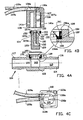
- the coupling piece 104 shown in figures 4A-C corresponds to some extent to the coupling piece 4 discussed above, though differs from it on some points.
- a housing 114 made of synthetic material, having a passage 115, a connection end 116 and a discharge end 117.
- a circular collar 139 is formed on the housing 114, the collar having a passage 170 that is transverse to the passage 115 and is in open connection to it.
- the passage 170 is limited by a shoulder 133 and an edge 134 above it, on which a sealing ring 122 is placed.
- Said sealing ring 122 is further shown in figure 4B , and has an outer ring 156, which to the inside merges in a wedge-shaped lip 155 that is formed as a unity with it.
- the ring 155 is able to deform in the direction M for the sealing.
- the ring 122 is made of suitable rubber material, in which metal reinforcement rings 156a and 156b have been integrally formed.
- the top side of the ring 156 forms a shoulder 161, on which a metal support ring 160 may come to lie.
- Said metal support ring 160 forms a stop for the pressure spring 125 ( figure 5A ), and also protects the ring 122 against damage by the spring.
- the housing 114 is furthermore provided with a transverse guidance 140, that is formed complementary to the free piston 123 yet to be discussed.
- Said recess 140 is situated at two diametrically opposite sides of the inner wall of the passage 115.
- a shallow recess 120 is formed, for accommodation of the end of the piston 123, in the cleansing position.
- the free, in this example substantially straight circle cylindrical piston 123 is provided with a duct 131 extending in axial direction, that is turned at right angles to a little duct 132, that ends in discharge opening 129.
- a shoulder 151 is formed in the duct 131, for accommodation of an O-ring 154.
- a passage 150 is situated, in which pin 127 yet to be discussed can easily be inserted.
- a shoulder 185 is situated and above it a circumferential groove 152, in which an O-ring 153 is placed.
- the piston 123 has a narrowed portion 123b below the widened inner end 123a.
- a flat surface 180 is arranged in the narrowed portion 123b, at one side, at the side where the opening 129 is situated, forming a recess with respect to the circumference of the narrowed portion 123b.
- extension 118 is shown forming a straight circle cylindrical chamber 119, and at the lower end or outer end being provided with a collar 138, that snugly fits in the edge 134 also lying on support ring 160.
- the extension 118 can be glued to the housing 114 and/or by means of screws (not shown) that are to be inserted into holes 163a,b.
- a pin 127 Fixedly attached in the extension 118 is a pin 127, forming a continuous duct 127a, that is in communication with the supply hose 109a, for, at choice, compressed air, water and cleansing medium, such as iodine.
- said line 109a ends in connection 130a eccentrically with respect tot he chamber 119, and thus the pin 127 is also eccentric, just like in the example discussed earlier.
- a separate line 109b is present for compressed air, with which in the assembled situation, a delivery pressure can be put on the top side or inner side of the piston 123 -via centric connection 130b-, for axial movement of the piston 123. Said pressure hits the inner surface of the widened head 123a of the piston 123, and said pressure cannot leave as a result of the O-ring 153.
- the extension 118 is further provided with drainage holes or drainage slits 141a, 141b, that open in the free atmosphere.
- FIG 5A the situation immediately after milking is shown.
- the last milk has flown down in the direction A.
- compressed air from the direction D is supplied via line 109b, as a result of which, for the above-mentioned reasons, the piston 123 is urged in the direction F.
- the piston Guided by the guidances 140 the piston finally arrives with its end in shallow recess 120, and because of the snugly fitting design the passage 115 is then closed off, in correspondence with the situation of figures 2B/3B .
- rinsing water can be supplied in the direction E through the duct 109a, which rinsing water flows via the pin 127 then accommodated in the duct 131, the pin 127 being short enough for the rinsing water to enter the little duct 132, in order to come out in the direction L and then flowing around the narrowed piston portion 123b and the spring 125 to finally come out through the now lowermost drainage hole 141a in the direction M.
- the sealing ring 122 with lip 155 here ensures that no rinsing water with possible iodine residues ends up in passage 115.
- a coupling piece 204 is first shown in figures 6A,B having an input end 217 situated at the teat cup side and an end 216 leading to the milk collection chamber, in which coupling piece a milk passage 215 is formed.
- the coupling piece 204 has a circular cross-section at the ends 216 and 217, which however in the cross-section of figures 6B,D taper with walls 292, 293, and in the cross-section in figures 6A,C flares of towards the middle of the coupling piece 204.
- a truncated conical closing body 223 is accommodated rotatable about its centre line and snugly fitting in said conical space.
- Said closing body 223 has an inner cavity 290 limited by wall 296 in which two holes 291a, 291b are formed that are situated diametrically opposite each other.
- a duct 227 extends through the closing body 223, which duct is connected to a line 209 for compressed air/cleansing medium, and possibly water.
- the duct 227 is turned at right angles in order to debouch in passage 215 at the location of the discharge opening 229, coinciding with the centre line of passage 215 and directed towards the end 217.
- the closing body 223 is attached in the coupling piece 204 with suitable means, such as for instance a threaded end/bolt, washer connection, against movement along its centre line.
- suitable means such as for instance a threaded end/bolt, washer connection, against movement along its centre line.
- Other means, and sealing rings where needed, can be provided. This embodiment is meant to be schematically shown.
- milk can flow in the direction A of the teat cup, through the passage 215, through hole 291a, space 290, hole 291b and further to a milk collection point.
- the closing body 223 When milking is completed the closing body 223 is turned in the direction P over 90° by means of remote controllable means that are not further shown. Then the situation shown in the figures 6C,D is achieved, in which the discharge opening 229, which in the situation of the figures 6A,B is either shielded or closed off by the cone wall 294, has been released and lies in the centre line of the coupling piece 204. Compressed air with cleansing medium is then supplied in the direction R through line 209, and squirts in the direction S out of the discharge opening 229.
Landscapes
- Life Sciences & Earth Sciences (AREA)
- Animal Husbandry (AREA)
- Environmental Sciences (AREA)
- External Artificial Organs (AREA)
- Dairy Products (AREA)
- Apparatus For Making Beverages (AREA)
- Cleaning In General (AREA)
Claims (19)
- Vorrichtung (1) zum pneumatischen Melken einer Kuh, die eine Anzahl von Milch-Absaugeinrichtungen umfasst, die jeweils einen Zitzenbecher (5) sowie eine mit dem unteren Ende des Zitzenbechers verbundene Milchleitung (6) umfassen, wobei die Leitung von dem Zitzenbecher zu einer Sammelkammer (7) für die Milch aus den Zitzenbechern führt und jede Milch-Absaugeinrichtung mit einer Zufuhr für ein Reinigungsmedium, wie beispielsweise ein Desinfektionsmittel, zu dem Zitzenbecher, insbesondere einer in dem Zitzenbecher befindlichen Zitze, versehen ist, die Zufuhr eine Leitung (109a, 127a, 131, 132) umfasst, die einen Endabschnitt mit einem Ausstoßende (132) hat, und jede Milch-Absaugeinrichtung mit einer Einrichtung versehen ist, mit der der Durchlass (115) der Milch-Absaugeinrichtung an dem Ausstoßende der Leitung für das Reinigungsmedium oder diesem nachgelagert, vorzugsweise auf der Höhe des Ausstoßendes, abgesperrt wird, wenn das Reinigungsmedium ausgestoßen wird,
dadurch gekennzeichnet, dass
die Absperreinrichtung einen beweglichen Absperrkörper (123) umfasst, der zwischen einer Position, in der der Durchlass (115) der Milch-Absaugeinrichtung frei bleibt, und einer Position bewegt werden kann, in der er abgesperrt wird, der Absperrkörper mit einer Ausstoßdüse bzw. einer Spritzleitung (129, 132) versehen ist, die den Endabschnitt mit Ausstoßende für die Leitung für die Zufuhr von Reinigungsmedium bildet und so positioniert ist, dass sie in die Milch-Absaugeinrichtung, insbesondere die Milchleitung, einmündet, wenn sie sich in der Absperrposition befindet, der Absperrkörper (123) durch einen vorzugsweise freien Kolben gebildet wird, der sich hin- und herbewegt oder gleitend, vorzugsweise quer zu der Milchleitung, in einer Kammer (119) gelagert ist, die in die Milch-Absaugeinrichtung einmündet und vorzugsweise quer dazu positioniert ist, wobei der Kolben an einem Abschnitt, der sich innerhalb des Ausstoßendes bzw. der Öffnung (129) befindet, mit einer Aussparung, einem Kanal oder dergleichen (180) versehen ist, die/der dazu dient, Fluidverbindung eines Raums (181) in der Milch-Absaugeinrichtung, dem Kolben vorgelagert, und der Kammer in der abgesperrten Position herzustellen, wenn sich der Kolben in der Absperrposition befindet. - Vorrichtung nach Anspruch 1, wobei die Aussparung eine Einebnung bzw. Abflachung (180) in der Oberfläche des Kolbens ist.
- Vorrichtung nach Anspruch 2, wobei die Abflachung (180) an der Seite angeordnet ist, an der sich das Ausstoßende bzw. die Öffnung befindet.
- Vorrichtung nach Anspruch 1, 2 oder 3, wobei die Kammer (119) mit Ableitlöchern (141a, 141 b) versehen ist.
- Vorrichtung nach Anspruch 4, wobei in der Absperrposition des Kolbens die Ableitlöcher (141a, 141 b) in Fluidverbindung mit der Aussparung (180) stehen.
- Vorrichtung nach einem der Ansprüche 1-5, wobei die Kammer (118) in der Nähe der Verbindung mit der Milch-Absaugeinrichtung mit einer Dichtung (122) für dichtenden Eingriff am Umfang des Kolbens versehen ist.
- Vorrichtung nach Anspruch 6, wobei der Kolben (123) einen verengten Abschnitt (123b) aufweist, der sich in einem radialen Abstand zu der Innenfläche der Kammer befindet, und die Dichtung (122) um den verengten Kolbenabschnitt herum in Eingriff ist.
- Vorrichtung nach Anspruch 6 oder 7, wobei die Dichtung ein Ring (122) ist, der eine Dichtungslippe (155) hat, die zu der Kammer-Innenseite hin ausgerichtet ist.
- Vorrichtung nach einem der vorangehenden Ansprüche, wobei die Ausstoßöffnung (132) in dem Kolben (123) im Wesentlichen radial, vorzugsweise in einer Richtung im Wesentlichen parallel zu dem Durchlass der Milch-Absaugeinrichtung und auf den Zitzenbecher zu, ausgerichtet ist.
- Vorrichtung nach den Ansprüchen 6 und 9, wobei in der eingezogenen, freien Position des Kolbens (123) sich das Ausstoßende (132) bzw. die Öffnung an der Innenseite der Dichtung (122) öffnet und die Dichtung um ein Kolbenende herum aktiv ist, das sich außerhalb derselben befindet.
- Vorrichtung nach einem der vorangehenden Ansprüche, wobei der Kolben (123) ein freier Kolben ist und er an seinem inneren Ende mit einem Kanal (131) versehen ist, in dem sich ein stationärer Bolzen (127) erstreckt, der Kanal Teil der Spritzleitung ist, der Bolzen vorzugsweise einen Durchlass (127a), vorzugsweise für permanente Fluidverbindung des Kanals mit der Zuführleitung, aufweist und eine Einrichtung zum pneumatischen Bewegen des Körpers durch eine Druckluftleitung separat von der Zuführleitung gebildet wird.
- Vorrichtung nach einem der vorangehenden Ansprüche, wobei der Kolben (123) an dem inneren Ende mit einer Dichtung (153) zum Abdichten an der Innenfläche der Kammer (119) versehen ist und eine Zuführleitung wenigstens für Druckluft in der Kammer in ein Ende der Kammer einmündet, das der Innenseite des Kolbens gegenüberliegend angeordnet ist.
- Vorrichtung nach Anspruch 11, wobei der Kolben (123) einen kreisförmigen Querschnitt hat und der Kanal exzentrisch in dem Kolben angeordnet ist.
- Vorrichtung nach einem der vorangehenden Ansprüche, die des Weiteren mit einer Einrichtung (109b) zum Durchlassen von Wasser, insbesondere in Form eines pulsierenden Wasser-/Luft-Gemischs, durch die Zuführleitung für das Reinigungsmedium zu dem Ausstoßende versehen ist
- Vorrichtung nach einem der vorangehenden Ansprüche, wobei die Absperreinrichtung in einem Kupplungsteil (114) aufgenommen ist, das in der Milch-Absaugeinrichtung, vorzugsweise in der Nähe des Übergangs zwischen dem Zitzenbecher (5) und der Milchleitung (6), aufgenommen ist.
- Anordnung aus einer Anzahl von Vorrichtungen nach einem der Ansprüche 1-15 und einem zentralen Milchspeicher, der mit der Milchsammelkammer verbunden ist.
- Verfahren zum Melken einer Kuh unter Verwendung einer Vorrichtung zum pneumatischen Melken einer Kuh, die einen Milchaustritt und einen damit verbundenen Zitzenbecher umfasst, wobei der Milchaustritt nach dem Melken abgesperrt wird, indem ein Absperrkörper von einer Position, an der der Milchaustritt offengehalten wird, an eine Position bewegt wird, an der der Milchaustritt abgesperrt gehalten wird, Reinigungsmedium über den Absperrkörper ausgestoßen wird, indem es in dem Milchaustritt auf den Zitzenbecher zu gespritzt wird, wobei, wenn die Zitzenbecher noch an der Kuh angebracht sind, das Reinigungsmittel in der Absperrposition des Absperrkörpers auf den Absperrkörper zurückfällt und von der Seite des Absperrkörpers, die dem Zitzenbecher zugewandt ist, zu einer Kammer, insbesondere einer Kammer, abgeleitet wird, in der der Absperrkörper in der offenen Position aufgenommen werden kann.
- Verfahren nach Anspruch 17, wobei das in die Kammer abgeleitete Reinigungsmittel über Ableitlöcher aus der Kammer nach außen gelangt.
- Verfahren nach Anspruch 18, wobei der Absperrkörper anschließend an die offene Position bewegt wird, die Kammer in Bezug auf den Milchaustritt abgedichtet wird, und anschließend ein Wasser-/Luft-Gemisch wieder über den Absperrkörper ausgestoßen wird, um die Kammer zu spülen, und die Spülflüssigkeit über Ableitlöcher austritt.
Applications Claiming Priority (3)
| Application Number | Priority Date | Filing Date | Title |
|---|---|---|---|
| NL1016237 | 2000-09-22 | ||
| NL1016237A NL1016237C2 (nl) | 2000-09-22 | 2000-09-22 | Melkinrichting voorzien van reinigingsmiddelen. |
| EP01979075A EP1328148B1 (de) | 2000-09-22 | 2001-09-21 | Melkvorrichtung mit reinigungsmitteln |
Related Parent Applications (2)
| Application Number | Title | Priority Date | Filing Date |
|---|---|---|---|
| EP01979075.7 Division | 2001-09-21 | ||
| EP01979075A Division EP1328148B1 (de) | 2000-09-22 | 2001-09-21 | Melkvorrichtung mit reinigungsmitteln |
Publications (2)
| Publication Number | Publication Date |
|---|---|
| EP1543720A1 EP1543720A1 (de) | 2005-06-22 |
| EP1543720B1 true EP1543720B1 (de) | 2011-12-28 |
Family
ID=19772123
Family Applications (2)
| Application Number | Title | Priority Date | Filing Date |
|---|---|---|---|
| EP05075562A Expired - Lifetime EP1543720B1 (de) | 2000-09-22 | 2001-09-21 | Melkvorrichtung mit Reinigungsmitteln |
| EP01979075A Expired - Lifetime EP1328148B1 (de) | 2000-09-22 | 2001-09-21 | Melkvorrichtung mit reinigungsmitteln |
Family Applications After (1)
| Application Number | Title | Priority Date | Filing Date |
|---|---|---|---|
| EP01979075A Expired - Lifetime EP1328148B1 (de) | 2000-09-22 | 2001-09-21 | Melkvorrichtung mit reinigungsmitteln |
Country Status (8)
| Country | Link |
|---|---|
| US (4) | US7281493B2 (de) |
| EP (2) | EP1543720B1 (de) |
| AU (1) | AU2002211064A1 (de) |
| DE (1) | DE60109312T2 (de) |
| ES (1) | ES2239683T3 (de) |
| GB (1) | GB2384682A (de) |
| NL (1) | NL1016237C2 (de) |
| WO (1) | WO2002023976A1 (de) |
Cited By (8)
| Publication number | Priority date | Publication date | Assignee | Title |
|---|---|---|---|---|
| US8336502B2 (en) | 2008-11-10 | 2012-12-25 | Gea Farm Technologies Gmbh | Method and device for automatically bringing a fluid into contact with the teats of an animal |
| US8528500B2 (en) | 2004-06-12 | 2013-09-10 | Gea Farm Technologies, Inc. | Automatic dairy animal milker unit backflusher and teat dip applicator system and method |
| US8590486B2 (en) | 2004-06-12 | 2013-11-26 | Gea Farm Technologies, Inc. | Safety valve for an automatic dairy animal milker unit backflusher and teat dip applicator |
| US8770146B2 (en) | 2009-09-04 | 2014-07-08 | Gea Farm Technologies, Inc. | Methods and apparatus for applying teat dip to a dairy animal |
| US8925483B2 (en) | 2010-02-22 | 2015-01-06 | Gea Farm Technologies, Inc. | Dairy harvesting facility with milk line protection system and methods |
| US8991335B2 (en) | 2008-06-27 | 2015-03-31 | Gea Farm Technologies, Inc. | Milk tube dome with flow controller |
| US9072273B2 (en) | 2004-06-12 | 2015-07-07 | Gea Farm Technologies, Inc. | Automatic dairy animal milker unit backflusher and teat dip applicator system and method |
| US9526224B2 (en) | 2013-12-20 | 2016-12-27 | Gea Farm Technologies Gmbh | Safety valve device |
Families Citing this family (25)
| Publication number | Priority date | Publication date | Assignee | Title |
|---|---|---|---|---|
| US20080022932A1 (en) * | 2001-09-21 | 2008-01-31 | Westfaliasurge, Inc. | Milking device provided with cleansing means |
| US7290497B2 (en) * | 2001-09-21 | 2007-11-06 | Westfaliasurge, Inc. | Milking device provided with cleansing means |
| NL1016237C2 (nl) * | 2000-09-22 | 2002-03-25 | Rieberjo B V | Melkinrichting voorzien van reinigingsmiddelen. |
| SE0201596D0 (sv) * | 2002-05-29 | 2002-05-29 | Delaval Holding Ab | A device for cleaning the teats of an animal |
| PL1790217T3 (pl) | 2003-10-22 | 2013-09-30 | An Udder Ip Company Ltd | Sprzęt udojowy |
| GB0408968D0 (en) | 2004-04-22 | 2004-05-26 | Duke James R J | Milking equipment |
| WO2005072516A1 (en) | 2004-01-30 | 2005-08-11 | James Richard John Duke | Milking equipment |
| US10874084B2 (en) | 2004-06-12 | 2020-12-29 | Gea Farm Technologies, Inc. | Safety valve for a dairy system component |
| US7401573B2 (en) | 2004-06-12 | 2008-07-22 | Westfaliasurge, Inc. | Liner contact automatic teat dip applicator |
| EP1788863A1 (de) * | 2004-09-14 | 2007-05-30 | WestfaliaSurge GmbH | Zitzenbecher und verfahren zum in kontakt bringen eines fluids mit einer zitze eines tieres |
| US20070022961A1 (en) * | 2005-08-01 | 2007-02-01 | Wheeler Raymond C | Colostrum collection system |
| GB0518976D0 (en) | 2005-09-16 | 2005-10-26 | Duke James R J | Teat cup |
| NL1031749C2 (nl) | 2006-05-04 | 2007-11-06 | Jacob Hendrik Berthold Dietric | Melkklauwinrichting. |
| NL1031764C2 (nl) | 2006-05-08 | 2007-11-13 | Jacob Hendrik Berthold Dietric | Melkklauwinrichting eventueel met reinigingsfunctie. |
| US20080095203A1 (en) * | 2006-10-19 | 2008-04-24 | Bratkovski Alexandre M | Multi-emitter image formation with reduced speckle |
| AU2010290055B2 (en) * | 2009-09-04 | 2015-07-30 | Gea Farm Technologies, Inc. | Automatic dairy animal milker unit backflusher and teat dip applicator system and method |
| US11723341B2 (en) | 2009-09-04 | 2023-08-15 | Gea Farm Technologies, Inc. | Safety valve for an automated milker unit backflushing and teat dip applicator system |
| USD624715S1 (en) * | 2009-11-10 | 2010-09-28 | Gea Farm Technologies Gmbh | Milking machine |
| US20120097107A1 (en) | 2010-02-22 | 2012-04-26 | Gea Farm Technologies, Inc. | Dairy animal milking preparation system and methods |
| GB201213231D0 (en) | 2012-07-25 | 2012-09-05 | An Udder Company Ltd | Milking equipment |
| DE102012215751A1 (de) * | 2012-09-05 | 2014-03-06 | Jakob Maier | Automatische Reinigungsanlage und Verfahren zur Reinigung/Behandlung von Zitzen eines Milchtieres |
| NL2010864C2 (en) * | 2013-05-27 | 2014-12-01 | M Van Wenum Holding B V | Disinfection dip system for a nipple. |
| DE102013114595B4 (de) | 2013-12-20 | 2026-01-15 | Gea Farm Technologies Gmbh | Sicherheitsventil |
| DE102016108300A1 (de) | 2016-05-04 | 2017-11-09 | Gea Farm Technologies Gmbh | Sicherheitsventil |
| WO2019090136A1 (en) | 2017-11-03 | 2019-05-09 | Gea Farm Technologies, Inc. | Automated milking system safety valve arrangement |
Family Cites Families (29)
| Publication number | Priority date | Publication date | Assignee | Title |
|---|---|---|---|---|
| US2747544A (en) * | 1948-08-18 | 1956-05-29 | Babson Bros Co | Teat cup support assembly |
| DE1299165B (de) * | 1966-06-06 | 1969-07-10 | Maier Jakob | Melkbecher fuer Melkmaschinen |
| US3973520A (en) * | 1974-09-30 | 1976-08-10 | Flocchini Andrew J | Automated milking assembly |
| US3958584A (en) * | 1975-04-10 | 1976-05-25 | Leon Jones | System for flushing of a milking machine |
| DE2622794A1 (de) * | 1976-05-21 | 1977-12-08 | Alfa Laval Agrar Gmbh | Verfahren und vorrichtung zur automatisierten anwendung von sanitisern an strichen und melkzeug |
| US4175514A (en) * | 1977-05-19 | 1979-11-27 | Frank F. Souza, Inc. | Automatic milking machine control and cleansing |
| US4222346A (en) * | 1978-11-29 | 1980-09-16 | Reisgies Rolf W | Milk line back flushing method and apparatus |
| DE3020758A1 (de) * | 1980-05-31 | 1981-12-10 | Jörn Dr. 2300 Kiel Hamann | Verfahren und vorrichtung zur verhinderung der benetzung von zitzenspitzen durch einen rueckstrom |
| US4333421A (en) * | 1980-06-18 | 1982-06-08 | Dec International, Inc. | Milking unit support and detacher mechanism |
| US4498419A (en) * | 1982-10-18 | 1985-02-12 | Flocchini Andrew J | Backwash valve and system for teat cup assembly |
| DE3406878C1 (de) * | 1984-02-25 | 1985-06-20 | Westfalia Separator Ag, 4740 Oelde | Trag- und Abziehmechanismus fuer Melkzeuge |
| US4803979A (en) * | 1987-05-27 | 1989-02-14 | Fischer Edmund C | Pulsating water and air jet structure for cleaning helmet window |
| IL94341A (en) * | 1990-05-09 | 1992-09-06 | Afikim S A E | System for disinfecting milking apparatus |
| GB9224405D0 (en) * | 1992-11-20 | 1993-01-13 | Silsoe Research Inst | Cleaning of milking animal teats |
| NL9301099A (nl) * | 1993-06-24 | 1995-01-16 | Texas Industries Inc | Inrichting voor het automatisch melken van dieren. |
| NL9400241A (nl) * | 1994-02-17 | 1995-10-02 | Prolion Bv | Besturingswijze voor een melkbehandelingssysteem en op deze wijze bestuurde melkinrichting. |
| NL9401113A (nl) * | 1994-07-04 | 1996-02-01 | Maasland Nv | Constructie met een inrichting voor het automatisch melken van dieren. |
| NL9401801A (nl) * | 1994-08-23 | 1996-04-01 | Maasland Nv | Constructie met een inrichting voor het melken van dieren. |
| NL9401451A (nl) * | 1994-09-07 | 1996-04-01 | Maasland Nv | Inrichting en werkwijze voor het melken van dieren. |
| NL1004921C2 (nl) * | 1996-12-31 | 1998-07-01 | Prolion Bv | Inrichting en werkwijze voor het melken van dieren. |
| NL1004922C2 (nl) * | 1996-12-31 | 1998-07-01 | Prolion Bv | Inrichting en werkwijze voor het melken van dieren. |
| US5960736A (en) * | 1997-04-17 | 1999-10-05 | Cornell Research Foundation, Inc. | Vacuum level control system using variable frequency drive |
| US5896828A (en) * | 1997-05-22 | 1999-04-27 | Alfa Laval Agri Inc. | Method and apparatus for cleaning milking pipelines and milking equipment |
| DE69906288T2 (de) * | 1998-06-22 | 2003-12-04 | Rieberjo B.V., Gorssel | Melkvorrichtung mit reinigungsmitteln |
| NL1010323C2 (nl) * | 1998-10-15 | 2000-04-18 | Maasland Nv | Werkwijze voor het automatisch melken van dieren en volautomatische melkmachine met een melkrobot geschikt voor het uitvoeren van de werkwijze. |
| NL1015803C2 (nl) | 2000-07-25 | 2002-01-28 | Nedap Nv | Inrichting bestemd voor het injecteren van een flu´dum in een systeem dat een melkbeker en een melkleiding omvat. |
| US7290497B2 (en) | 2001-09-21 | 2007-11-06 | Westfaliasurge, Inc. | Milking device provided with cleansing means |
| NL1016237C2 (nl) * | 2000-09-22 | 2002-03-25 | Rieberjo B V | Melkinrichting voorzien van reinigingsmiddelen. |
| US6997135B1 (en) * | 2003-10-08 | 2006-02-14 | Dewaard Dave | Valve for a milking apparatus |
-
2000
- 2000-09-22 NL NL1016237A patent/NL1016237C2/nl not_active IP Right Cessation
-
2001
- 2001-09-21 AU AU2002211064A patent/AU2002211064A1/en not_active Abandoned
- 2001-09-21 GB GB0310227A patent/GB2384682A/en not_active Withdrawn
- 2001-09-21 DE DE60109312T patent/DE60109312T2/de not_active Expired - Lifetime
- 2001-09-21 EP EP05075562A patent/EP1543720B1/de not_active Expired - Lifetime
- 2001-09-21 EP EP01979075A patent/EP1328148B1/de not_active Expired - Lifetime
- 2001-09-21 WO PCT/NL2001/000699 patent/WO2002023976A1/en not_active Ceased
- 2001-09-21 ES ES01979075T patent/ES2239683T3/es not_active Expired - Lifetime
-
2003
- 2003-03-20 US US10/393,431 patent/US7281493B2/en not_active Expired - Lifetime
-
2007
- 2007-01-10 US US11/652,372 patent/US20070186860A1/en not_active Abandoned
- 2007-10-15 US US11/974,682 patent/US7765951B2/en not_active Expired - Lifetime
-
2008
- 2008-08-20 US US12/229,219 patent/US20090064937A1/en not_active Abandoned
Cited By (13)
| Publication number | Priority date | Publication date | Assignee | Title |
|---|---|---|---|---|
| US9510556B2 (en) | 2004-06-12 | 2016-12-06 | Gea Farm Technologies, Inc. | Dosage valve for a backflushing and teat dip applicator system |
| US8528500B2 (en) | 2004-06-12 | 2013-09-10 | Gea Farm Technologies, Inc. | Automatic dairy animal milker unit backflusher and teat dip applicator system and method |
| US8590486B2 (en) | 2004-06-12 | 2013-11-26 | Gea Farm Technologies, Inc. | Safety valve for an automatic dairy animal milker unit backflusher and teat dip applicator |
| US9072273B2 (en) | 2004-06-12 | 2015-07-07 | Gea Farm Technologies, Inc. | Automatic dairy animal milker unit backflusher and teat dip applicator system and method |
| US9468189B2 (en) | 2004-06-12 | 2016-10-18 | Gea Farm Technologies, Inc. | Safety valve for an automated milker unit backflushing and teat dip applicator system |
| US9491925B2 (en) | 2004-06-12 | 2016-11-15 | Gea Farm Technologies, Inc. | Valve block for a backflushing and teat dip applicator system |
| US9545079B2 (en) | 2008-06-27 | 2017-01-17 | Gea Farm Technologies, Inc. | Milk tube dome with flow controller |
| US8991335B2 (en) | 2008-06-27 | 2015-03-31 | Gea Farm Technologies, Inc. | Milk tube dome with flow controller |
| US8336502B2 (en) | 2008-11-10 | 2012-12-25 | Gea Farm Technologies Gmbh | Method and device for automatically bringing a fluid into contact with the teats of an animal |
| US8770146B2 (en) | 2009-09-04 | 2014-07-08 | Gea Farm Technologies, Inc. | Methods and apparatus for applying teat dip to a dairy animal |
| US9504226B2 (en) | 2009-09-04 | 2016-11-29 | Gea Farm Technologies, Inc. | Methods and apparatus for applying teat dip to a dairy animal |
| US8925483B2 (en) | 2010-02-22 | 2015-01-06 | Gea Farm Technologies, Inc. | Dairy harvesting facility with milk line protection system and methods |
| US9526224B2 (en) | 2013-12-20 | 2016-12-27 | Gea Farm Technologies Gmbh | Safety valve device |
Also Published As
| Publication number | Publication date |
|---|---|
| EP1328148B1 (de) | 2005-03-09 |
| US20090064937A1 (en) | 2009-03-12 |
| ES2239683T3 (es) | 2005-10-01 |
| US20080083373A1 (en) | 2008-04-10 |
| DE60109312T2 (de) | 2006-04-06 |
| US7765951B2 (en) | 2010-08-03 |
| DE60109312D1 (de) | 2005-04-14 |
| EP1328148A1 (de) | 2003-07-23 |
| GB2384682A (en) | 2003-08-06 |
| US20070186860A1 (en) | 2007-08-16 |
| NL1016237C2 (nl) | 2002-03-25 |
| EP1543720A1 (de) | 2005-06-22 |
| US20030226520A1 (en) | 2003-12-11 |
| WO2002023976A1 (en) | 2002-03-28 |
| AU2002211064A1 (en) | 2002-04-02 |
| US7281493B2 (en) | 2007-10-16 |
Similar Documents
| Publication | Publication Date | Title |
|---|---|---|
| EP1543720B1 (de) | Melkvorrichtung mit Reinigungsmitteln | |
| US7290497B2 (en) | Milking device provided with cleansing means | |
| US20080022932A1 (en) | Milking device provided with cleansing means | |
| US8210123B2 (en) | Teat cup | |
| EP1089615B1 (de) | Melkvorrichtung mit reinigungsmitteln | |
| EP1679956B2 (de) | Melkausrüstung und -verfahren | |
| EP1219167B1 (de) | Vorrichtung zum Melken von Tieren, so wie Kühen | |
| EP2056669B1 (de) | Milchsammelvorrichtung, wahlweise mit reinigungsfunktion | |
| WO2005072516A1 (en) | Milking equipment | |
| US9861069B2 (en) | Claw for a milking machine | |
| CA3021980C (en) | Mechanized milking machine including a device for injection of a product for rinsing the pipe for routing of the milk to the milk tank | |
| RU2084136C1 (ru) | Доильный аппарат винникова и.к. | |
| EP1744616B1 (de) | Melkvorrichtung und verbinderglied | |
| CZ277892B6 (en) | Teat-cup with automatic closure |
Legal Events
| Date | Code | Title | Description |
|---|---|---|---|
| PUAI | Public reference made under article 153(3) epc to a published international application that has entered the european phase |
Free format text: ORIGINAL CODE: 0009012 |
|
| AC | Divisional application: reference to earlier application |
Ref document number: 1328148 Country of ref document: EP Kind code of ref document: P |
|
| AK | Designated contracting states |
Kind code of ref document: A1 Designated state(s): DE ES GB NL SE |
|
| 17P | Request for examination filed |
Effective date: 20051130 |
|
| AKX | Designation fees paid |
Designated state(s): DE ES GB NL SE |
|
| GRAP | Despatch of communication of intention to grant a patent |
Free format text: ORIGINAL CODE: EPIDOSNIGR1 |
|
| GRAC | Information related to communication of intention to grant a patent modified |
Free format text: ORIGINAL CODE: EPIDOSCIGR1 |
|
| RIN1 | Information on inventor provided before grant (corrected) |
Inventor name: BERTHOLD, JOHANNES T. D. |
|
| GRAS | Grant fee paid |
Free format text: ORIGINAL CODE: EPIDOSNIGR3 |
|
| GRAA | (expected) grant |
Free format text: ORIGINAL CODE: 0009210 |
|
| AC | Divisional application: reference to earlier application |
Ref document number: 1328148 Country of ref document: EP Kind code of ref document: P |
|
| AK | Designated contracting states |
Kind code of ref document: B1 Designated state(s): DE ES GB NL SE |
|
| REG | Reference to a national code |
Ref country code: GB Ref legal event code: FG4D |
|
| REG | Reference to a national code |
Ref country code: DE Ref legal event code: R096 Ref document number: 60145886 Country of ref document: DE Effective date: 20120301 |
|
| REG | Reference to a national code |
Ref country code: NL Ref legal event code: T3 |
|
| PG25 | Lapsed in a contracting state [announced via postgrant information from national office to epo] |
Ref country code: SE Free format text: LAPSE BECAUSE OF FAILURE TO SUBMIT A TRANSLATION OF THE DESCRIPTION OR TO PAY THE FEE WITHIN THE PRESCRIBED TIME-LIMIT Effective date: 20111228 |
|
| PLBE | No opposition filed within time limit |
Free format text: ORIGINAL CODE: 0009261 |
|
| STAA | Information on the status of an ep patent application or granted ep patent |
Free format text: STATUS: NO OPPOSITION FILED WITHIN TIME LIMIT |
|
| 26N | No opposition filed |
Effective date: 20121001 |
|
| REG | Reference to a national code |
Ref country code: DE Ref legal event code: R097 Ref document number: 60145886 Country of ref document: DE Effective date: 20121001 |
|
| PGFP | Annual fee paid to national office [announced via postgrant information from national office to epo] |
Ref country code: ES Payment date: 20121126 Year of fee payment: 12 |
|
| PG25 | Lapsed in a contracting state [announced via postgrant information from national office to epo] |
Ref country code: ES Free format text: LAPSE BECAUSE OF FAILURE TO SUBMIT A TRANSLATION OF THE DESCRIPTION OR TO PAY THE FEE WITHIN THE PRESCRIBED TIME-LIMIT Effective date: 20120408 |
|
| PGFP | Annual fee paid to national office [announced via postgrant information from national office to epo] |
Ref country code: GB Payment date: 20200924 Year of fee payment: 20 Ref country code: DE Payment date: 20200923 Year of fee payment: 20 Ref country code: NL Payment date: 20200924 Year of fee payment: 20 |
|
| REG | Reference to a national code |
Ref country code: DE Ref legal event code: R071 Ref document number: 60145886 Country of ref document: DE |
|
| REG | Reference to a national code |
Ref country code: NL Ref legal event code: MK Effective date: 20210920 |
|
| REG | Reference to a national code |
Ref country code: GB Ref legal event code: PE20 Expiry date: 20210920 |
|
| PG25 | Lapsed in a contracting state [announced via postgrant information from national office to epo] |
Ref country code: GB Free format text: LAPSE BECAUSE OF EXPIRATION OF PROTECTION Effective date: 20210920 |
|
| PGFP | Annual fee paid to national office [announced via postgrant information from national office to epo] |
Ref country code: ES Payment date: 20221001 Year of fee payment: 12 |