EP1543883B1 - Ventilanordnung zum Mischen eines Mehrkomponenten-Lacks und zugehöriges Betriebsverfahren - Google Patents
Ventilanordnung zum Mischen eines Mehrkomponenten-Lacks und zugehöriges Betriebsverfahren Download PDFInfo
- Publication number
- EP1543883B1 EP1543883B1 EP04023208A EP04023208A EP1543883B1 EP 1543883 B1 EP1543883 B1 EP 1543883B1 EP 04023208 A EP04023208 A EP 04023208A EP 04023208 A EP04023208 A EP 04023208A EP 1543883 B1 EP1543883 B1 EP 1543883B1
- Authority
- EP
- European Patent Office
- Prior art keywords
- valve
- hardener
- paint
- conduit
- supply conduit
- Prior art date
- Legal status (The legal status is an assumption and is not a legal conclusion. Google has not performed a legal analysis and makes no representation as to the accuracy of the status listed.)
- Expired - Lifetime
Links
Images


Classifications
-
- B—PERFORMING OPERATIONS; TRANSPORTING
- B05—SPRAYING OR ATOMISING IN GENERAL; APPLYING FLUENT MATERIALS TO SURFACES, IN GENERAL
- B05B—SPRAYING APPARATUS; ATOMISING APPARATUS; NOZZLES
- B05B7/00—Spraying apparatus for discharge of liquids or other fluent materials from two or more sources, e.g. of liquid and air, of powder and gas
- B05B7/02—Spray pistols; Apparatus for discharge
- B05B7/04—Spray pistols; Apparatus for discharge with arrangements for mixing liquids or other fluent materials before discharge
- B05B7/0408—Spray pistols; Apparatus for discharge with arrangements for mixing liquids or other fluent materials before discharge with arrangements for mixing two or more liquids
-
- B—PERFORMING OPERATIONS; TRANSPORTING
- B05—SPRAYING OR ATOMISING IN GENERAL; APPLYING FLUENT MATERIALS TO SURFACES, IN GENERAL
- B05B—SPRAYING APPARATUS; ATOMISING APPARATUS; NOZZLES
- B05B12/00—Arrangements for controlling delivery; Arrangements for controlling the spray area
- B05B12/14—Arrangements for controlling delivery; Arrangements for controlling the spray area for supplying a selected one of a plurality of liquids or other fluent materials or several in selected proportions to a spray apparatus, e.g. to a single spray outlet
- B05B12/1409—Arrangements for controlling delivery; Arrangements for controlling the spray area for supplying a selected one of a plurality of liquids or other fluent materials or several in selected proportions to a spray apparatus, e.g. to a single spray outlet the selection means being part of the discharge apparatus, e.g. part of the spray gun
-
- B—PERFORMING OPERATIONS; TRANSPORTING
- B05—SPRAYING OR ATOMISING IN GENERAL; APPLYING FLUENT MATERIALS TO SURFACES, IN GENERAL
- B05B—SPRAYING APPARATUS; ATOMISING APPARATUS; NOZZLES
- B05B12/00—Arrangements for controlling delivery; Arrangements for controlling the spray area
- B05B12/14—Arrangements for controlling delivery; Arrangements for controlling the spray area for supplying a selected one of a plurality of liquids or other fluent materials or several in selected proportions to a spray apparatus, e.g. to a single spray outlet
- B05B12/1418—Arrangements for controlling delivery; Arrangements for controlling the spray area for supplying a selected one of a plurality of liquids or other fluent materials or several in selected proportions to a spray apparatus, e.g. to a single spray outlet for supplying several liquids or other fluent materials in selected proportions to a single spray outlet
-
- B—PERFORMING OPERATIONS; TRANSPORTING
- B05—SPRAYING OR ATOMISING IN GENERAL; APPLYING FLUENT MATERIALS TO SURFACES, IN GENERAL
- B05B—SPRAYING APPARATUS; ATOMISING APPARATUS; NOZZLES
- B05B15/00—Details of spraying plant or spraying apparatus not otherwise provided for; Accessories
- B05B15/50—Arrangements for cleaning; Arrangements for preventing deposits, drying-out or blockage; Arrangements for detecting improper discharge caused by the presence of foreign matter
- B05B15/55—Arrangements for cleaning; Arrangements for preventing deposits, drying-out or blockage; Arrangements for detecting improper discharge caused by the presence of foreign matter using cleaning fluids
-
- B—PERFORMING OPERATIONS; TRANSPORTING
- B05—SPRAYING OR ATOMISING IN GENERAL; APPLYING FLUENT MATERIALS TO SURFACES, IN GENERAL
- B05B—SPRAYING APPARATUS; ATOMISING APPARATUS; NOZZLES
- B05B12/00—Arrangements for controlling delivery; Arrangements for controlling the spray area
- B05B12/14—Arrangements for controlling delivery; Arrangements for controlling the spray area for supplying a selected one of a plurality of liquids or other fluent materials or several in selected proportions to a spray apparatus, e.g. to a single spray outlet
- B05B12/149—Arrangements for controlling delivery; Arrangements for controlling the spray area for supplying a selected one of a plurality of liquids or other fluent materials or several in selected proportions to a spray apparatus, e.g. to a single spray outlet characterised by colour change manifolds or valves therefor
Definitions
- the invention relates to a valve arrangement for producing a multicomponent varnish, in particular in the form of a mixer for producing a multicomponent water-based paint, according to the preamble of claim 1 and an operating method for such a valve arrangement according to the preamble of claim 12.
- a valve assembly for mixing such a multi-component paint which may be arranged for example on the arm of a painting robot and supplies the multi-component paint an atomizer, which is also attached to the arm of the painting robot.
- This known valve arrangement has a hardener feed line and a base paint feed line, which open into a common output line, wherein a controllable valve is arranged in the hardener feed line and in the base paint feed line.
- the known valve arrangement on a purge line which also opens via a purge valve in the common output line of the valve assembly.
- the two controllable valves in the hardener feed line and in the base paint feed line are open, whereas the flushing valve is closed, so that the parent lacquer in the common output line mixes with the hardener and forms the multi-component lacquer.
- the two controllable valves in the hardener supply line and the stem paint supply line are closed while the purge valve is opened, whereupon a water scavenger is introduced into the valve assembly and the common output line and the downstream of the hardener valve or the Stammlack valve located pipe sections of the hardener feed line and the base paint feed line cleans.
- a water scavenger is introduced into the valve assembly and the common output line and the downstream of the hardener valve or the Stammlack valve located pipe sections of the hardener feed line and the base paint feed line cleans.
- water rinsing agent and pulse air are introduced alternately.
- atmospheric moisture can also penetrate into the valve arrangement from the environment (for example from the paint booth, via the nozzle or via a hose) and trigger the above-described chemical reaction with the solvent-based hardener, which leads to irreversible damage, especially during a longer shutdown can lead.
- DE 1 900 518 A a spray device for liquid synthetic resins, in which a check valve is arranged behind a catalyst valve in a catalyst feed line.
- the U.S. 4,703,894 further discloses a two-component mixer which enables a spray gun removed from the paint reservoir and the hardener to be supplied with the two-component mixture.
- the invention is therefore based on the object to improve the known valve arrangement described above to the extent that a chemical reaction of the solvent-based hardener is prevented as much as possible with moisture from the water rinse, the pulse air or the environment.
- the invention includes the general technical teaching when flushing with a water rinse and / or blowing in moisture-containing pulse air and / or at a longer shutdown the hardener valve by a shut-off valve to a contact between the hardener and in the water rinse, the Pulse air or the ambient air contained moisture to prevent.
- the solvent-based hardener eg isocyanate
- a controllable shut-off valve is therefore arranged downstream of the hardener valve in order to seal off the hardener valve, the shut-off valve being arranged in the hardener feed line.
- a hardener supply line preferably comprises the entire line area for the supply of the curing agent upstream of the mouth of the base paint feed line.
- the hardener supply line is therefore not limited to the line region upstream of the shut-off valve or even upstream upstream of the hardener valve.
- controllability of the shut-off valve used in the context of the invention preferably means that the shut-off valve can be set independently of the input-side and / or output-side pressure, whereas, for example, a check valve opens or closes independently according to the input-side or output-side pressure.
- the shut-off valve is controllable by compressed air, however, the invention is not limited to a compressed air control of the shut-off valve. Rather, it is also possible to control the shut-off valve electrically, hydraulically or in any other way.
- the valve arrangement according to the invention preferably has a flushing agent supply line, which opens downstream behind the shut-off valve into the outlet line.
- a flushing agent is supplied via this flushing agent supply line, wherein the shut-off valve is closed during the flushing operation to prevent contact of the water flushing agent with the curing agent.
- pulsed air for cleaning the valve arrangement can also be injected via this flushing agent supply line, the shut-off valve also being closed during the blowing in order to prevent contact between the air humidity contained in the pulse air and the hardening agent.
- a separate pulse air supply line may be provided, which opens downstream behind the shut-off valve in the output line.
- the water rinsing agent can be supplied from an upstream color changer, for example in a color change on the stock paint feed line. In this case too, it is possible alternately to introduce water scavenging and pulsed air via the stock paint feed line.
- valve arrangement according to the invention preferably has a further flushing agent supply line, which opens into a line section between the hardener valve and the shut-off valve.
- a further flushing agent supply line which opens into a line section between the hardener valve and the shut-off valve.
- an additional rinsing agent which is based on solvent and / or is adapted to the hardener and therefore does not react with the hardener can be supplied via this rinsing agent feed line.
- This additional flushing agent may be used to remove moisture from the valve assembly as part of a flushing operation.
- the line section between the hardener valve and the shut-off valve is flooded with the solvent-based rinsing agent. This is especially advantageous for a longer shutdown, since the solvent-containing detergent then prevents as a barrier medium that the humidity slowly reacts with the hardener.
- Pulse air can also be blown into the valve arrangement according to the invention via this additional flushing agent supply line.
- a further additional pulse air supply line is provided, which opens into the line section between the hardener valve and the shut-off valve.
- a conventional hardener e.g., isocyanate
- no pulse air is injected through the additional detergent feed line, since the hardener could chemically react with the humidity contained in the pulse air, which can harden the hardener.
- a chamber is preferably arranged, which can be flooded during a business interruption with the solvent-containing rinsing agent, so that during the interruption of service at the hardener valve always solvent-based rinse acts as a barrier medium, whereby hardening of the hardener is prevented .
- the chamber between the hardener valve and the shut-off valve can be formed, for example, by a hose or a hose section.
- the shut-off valve is thus opened, so that the hardener can pass through the likewise opened hardener valve and the shut-off valve into the common outlet line in order to mix there with the master paint to the multi-component paint.
- shut-off valve For shorter downtimes then a normal flushing can be done by the water scavenger or pulse air is introduced downstream behind the shut-off valve, the hardener valve, the stem paint valve and the shut-off valve is closed.
- the closed shut-off valve prevents the water rinse from coming into contact with the hardener.
- an additional rinsing process is preferably carried out in order to prevent clumping which may occur due to the chemical reaction between the aqueous rinsing agent and the hardener.
- a conventional, solvent-containing detergent is preferably introduced into the valve assembly, wherein the introduction is preferably carried out between the hardener valve and the shut-off valve.
- the hardener valve and the stem paint valve are closed while the shut-off valve is open.
- residues of the hardener are rinsed out by this rinsing so that later hardenings during the interruption of operation are prevented.
- the shut-off valve is then preferably closed, so that the line region between the hardener valve and the shut-off valve during the stoppage of operation preferably remains filled with the solvent-containing detergent to prevent clumping during the stoppage.
- the solvent-containing detergent acts as a barrier medium, which prevents hardening of the hardener.
- the valve arrangement according to the invention therefore preferably has two detergent feed lines, wherein the one detergent feed line Preferably, an aqueous rinsing agent feeds and preferably downstream flows behind the shut-off valve in the common outlet line, while the other detergent feed line preferably an anhydrous, solvent-containing rinse supplies and preferably opens into the line section between the hardener valve and the shut-off valve.
- the one detergent feed line Preferably, an aqueous rinsing agent feeds and preferably downstream flows behind the shut-off valve in the common outlet line, while the other detergent feed line preferably an anhydrous, solvent-containing rinse supplies and preferably opens into the line section between the hardener valve and the shut-off valve.
- valve arrangement according to the invention may also have a return line, which branches off from the parent lacquer feed line and allows for a color change pressing and flushing the stem paint feed line.
- a color changer can be connected to the base paint feed line, which selects the master paint of the desired color from a plurality of available master paints and supplies it to the valve arrangement.
- a hardener changer can be connected to the hardener supply line, which supplies one of several different hardeners.
- the hardener valve, the stem paint valve and the flushing valves are integrated into the valve assembly according to the invention and part of the same.
- the invention also includes such embodiments in which these valves are designed as separate components and the valve assembly according to the invention are connected upstream.
- the invention is not limited to the valve arrangement described above, but also includes a corresponding operating method, in which the common output line for the multicomponent lacquer can be flushed separately from the hardener feed line.
- the separately flushable line sections of the hardener feed line on the one hand and the output line and / or the master paint feed line on the other hand in this case flushed with different detergents.
- a water-containing rinsing agent is preferably used for rinsing the output line and / or the base paint feed line, if the base coat based on water.
- an anhydrous, solvent-based rinse is preferably used to prevent a chemical reaction between the solvent-based hardener (eg isocyanate) and the rinse as this could lead to irreversible damage.
- FIG. 1b shows a rotary atomizer 1, which is constructed largely conventional, so that in the following no detailed description of the rotary atomizer 1 takes place and only the features essential to the invention are described.
- the front part of the rotary atomizer 1 is shown hatched here for the sake of simplicity, in order not to distract from the details essential to the invention.
- DE 93 21 294 U1 and DE 43 06 800 A1 the content of which is wholly attributable to the present description.
- the rotary atomizer 1 is used for coating parts, such as motor vehicle body parts, with a multi-component water-based paint, which consists of a hardener H and a parent lacquer SL, wherein the curing agent H in an in Fig. 1a schematically illustrated valve assembly 2 is mixed with the base paint SL.
- a multi-component water-based paint which consists of a hardener H and a parent lacquer SL, wherein the curing agent H in an in Fig. 1a schematically illustrated valve assembly 2 is mixed with the base paint SL.
- the valve arrangement 2 For supplying the master varnish SL, the valve arrangement 2 has a stem paint feed line 3, which starts from the end face of the valve arrangement 2 located on the left in the drawing and via a controllable stock paint valve 4 into a common outlet line 5 for the hardener H and the parent varnish SL opens, wherein the base paint valve 4 consists of a pneumatically actuated actuator 6 and a displaceably mounted valve needle 7. In its lower stop position, the valve needle 7 blocks the transition from the hardener supply line 3 in the common output line 5, while the transition is released in the raised position of the valve needle 7. The activation of the actuator 6 of the hardener valve 4 takes place via a compressed air control line 8, which is also of the in the drawing located on the left end face of the valve assembly 2 and ends at the actuator 6.
- a compressed air control line 8 which is also of the in the drawing located on the left end face of the valve assembly 2 and ends at the actuator 6.
- the valve assembly 2 For supplying the hardener H, the valve assembly 2 has a corresponding hardener supply line 9, which also starts from the left in the drawing end face of the valve assembly 2 and opens via a controllable hardener valve 10 into a chamber 11 or a corresponding line volume, said the hardener valve 10 consists of a pneumatically actuated actuator 12 and a valve needle 13 driven and displaceably mounted by the actuator 12.
- the valve needle In its lower stop position, the valve needle blocks the transition from the hardener feed line 9 into the chamber 11, so that no hardener H can penetrate into the chamber 11.
- the valve needle 13 releases the transition from the hardener feed line 9 into the chamber 11, so that the hardener H can pass from the hardener feed line 9 into the chamber 11.
- the actuation of the actuator 12 of the hardener valve 10 takes place pneumatically via a compressed air control line 14, which also starts from the left in the drawing end face of the valve assembly 2 and ends in the actuator 12.
- the chamber 11 in the valve assembly 2 is connected via a controllable shut-off valve 15 to the common output line 5, wherein the shut-off valve 15 consists essentially of an actuator 16 and a valve pin 17 driven by the actuator 16 and slidably mounted.
- the valve needle 17 blocks the transition from the chamber 11 in the common output line 5, so that no hardener H can enter from the chamber 11 in the output line 5.
- the valve needle 17 In the left-hand position in the drawing, the valve needle 17, however, the transition from the chamber 11 to the output line 5 free, so that the hardener H can get out of the chamber 11 in the output line 5, to mix there with the base paint SL to the multi-component water-based paint.
- the actuation of the actuator 16 of the check valve 15 is effected by a compressed air control line 18, which starts from the left in the drawing end face of the valve assembly 2 and is guided to the actuator 16.
- the valve assembly 2 For flushing the common output line 5, the valve assembly 2 has a flushing agent supply line 19, which starts from the left in the drawing end face of the valve assembly 2 and opens via a flushing valve 20 in the output line 5, wherein the flushing valve 20 from a pneumatically actuated actuator 21 and one of the actuator 21 driven and slidably mounted in the valve assembly 2 valve needle 22 consists. In its upper stop position in the drawing, the valve needle 22 obstructs the transition from the rinsing agent supply line 19 to the common output line 5, so that no rinsing takes place.
- valve needle 22 of the flushing valve 20 releases the transition from the flushing agent supply line 19 to the common outlet line 5, so that the rotary atomizer 1 can be flushed with a water-containing flushing agent V1 which is flushed over the flushing agent.
- Supply line 19 is supplied.
- the actuation of the actuator 21 of the flushing valve 20 is pneumatically by a compressed air control line 23, which starts from the left in the drawing end face of the valve assembly 2 and is guided to the actuator 21.
- a water-based rinsing agent is useful when using a multicomponent water-based paint, as the base varnish used is also based on water.
- valve assembly 2 a further detergent supply line 24 which emanates from the left in the drawing end face of the valve assembly 2 and via a flushing valve 25 opens into the chamber 11, wherein the flushing valve 25 from a pneumatically actuated actuator 26 and a consists of the actuator 26 mechanically driven and slidably mounted in the valve assembly 2 valve needle 27.
- the valve needle 27 of the flushing valve 25 blocks the transition from the flushing agent supply line 24 into the chamber 11, so that no flushing agent V2 is supplied.
- valve needle 27 of the flushing valve 25 releases the transition from the flushing agent supply line 24 to the chamber 11, so that the flushing agent V2 can enter the chamber 11 from the flushing agent supply line 24.
- the actuation of the actuator 26 takes place here pneumatically via a compressed air control line 28, which starts from the left in the drawing end face of the valve assembly 2 and is guided to the actuator 26 of the flushing valve 25.
- the rotary atomizer 1 still has a conventional main valve 29 which is arranged in the output line 5 and controls the delivery of the multicomponent aqueous paint, the main valve 29 in turn of a pneumatically actuated actuator 30 and one of the actuator 30 mechanically driven and in the rotary atomizer 1 slidably mounted valve needle 31 consists.
- the actuation of the actuator 30 takes place here pneumatically by a further compressed air control line 32, which starts from the left in the drawing end face of the valve assembly 2 and is guided to the actuator 30 of the main valve 29.
- the hardener valve 10 and the shut-off valve 15, however, are open during normal painting operation, so that the hardener H passes through the hardener valve 10, the chamber 11 and the open shut-off valve 15 in the output line 5, where the hardener H with the Stem varnish SL mixes, which also passes via the open stem paint valve 4 in the output line 5.
- the resulting multi-component water-based paint is then applied by the rotary atomizer 1 according to the valve position of the main valve 29.
- the flushing valve 20 is opened while the shut-off valve 15 and the other flushing valve 25 remain closed.
- Pulse air PL and a water-containing flushing agent V1 are then alternately supplied via the flushing agent supply line 19, which pass into the common outlet line 5 and clean it and the entire rotary atomizer 1 of residues of the 2-component paint.
- shut-off valve 15 and the flushing agent valve 25 are then closed, wherein the solvent-containing, anhydrous flushing agent V2 contained in the chamber 11 prevents water-containing flushing agent residues of the flushing agent V1 in the rotary atomizer 1 or the valve arrangement 2 from reacting chemically with the hardener H, which in extreme cases could lead to clogging of the hardener valve 10 and the other valves.
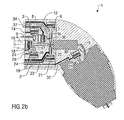
- FIGS. 2a and 2 B illustrated embodiment is largely consistent with that described above and in the FIGS. 1a and 1b illustrated embodiment, so reference is made to avoid repetition of the above description and the same reference numerals are used below for corresponding components.
- a special feature of this embodiment is that of the parent lacquer feed line 3 via a return valve 33rd a return line 34 branches off, wherein the return valve 33 in turn consists of a pneumatically actuated actuator 35 and a driven by the actuator 35 and slidably mounted in the valve assembly 2 valve needle 36.
- the valve needle 36 of the return valve 33 blocks the transition from the parent lacquer feed line 3 into the return line 34, so that no parent lacquer SL is returned.
- the valve needle 36 of the return valve 33 releases the transition from the stock paint feed line 3 to the return line 34, so that the base paint SL is returned.
- the recirculation valve 33 for the master varnish SL is used for pressing and flushing the stock paint feed line 3 when using several different master paints SL with the same hardener H.
- the various master stocks SL are then centrally connected to an upstream and not shown color changer and are as needed the rotary atomizer 1 is pressed.
- the control of the actuator 35 of the return valve 34 is again pneumatically by a compressed air control line 37th
Landscapes
- Nozzles (AREA)
- Spray Control Apparatus (AREA)
- Multiple-Way Valves (AREA)
Description
- Die Erfindung betrifft eine Ventilanordnung zur Herstellung eines Mehrkomponenten-Lacks, insbesondere in Form eines Mischers zur Herstellung eines Mehrkomponenten-Wasserlacks, gemäß dem Oberbegriff des Anspruchs 1 sowie ein Betriebsverfahren für eine derartige Ventilanordnung gemäß dem Oberbegriff des Anspruchs 12.
- Es ist in der Lackiertechnik bekannt, zur Lackierung von Teilen, wie beispielsweise Kraftfahrzeugkarosserieteilen, Mehrkomponenten-Lacke einzusetzen, die aus einem Stammlack und einem Härter gemischt werden. Bei derartigen Mehrkomponenten-Lacken kann der Stammlack wahlweise auf Lösemittelbasis oder auf Wasserbasis beruhen, wobei wässrige Mehrkomponenten-Lacke eine bessere Umweltverträglichkeit bieten. In beiden Fällen ist der Härter jedoch konventionell und beruht auf einer Lösemittelbasis.
- Aus
WO 97/00731 - Während des Lackierbetriebs sind die beiden steuerbaren Ventile in der Härter-Zuleitung und in der Stammlack-Zuleitung geöffnet, wohingegen das Spülmittelventil geschlossen ist, so dass sich der Stammlack in der gemeinsamen Ausgangsleitung mit dem Härter mischt und den Mehrkomponenten-Lack bildet.
- Zur Spülung und bei einem Farbwechsel werden die beiden steuerbaren Ventile in der Härter-Zuleitung und der Stammlack-Zuleitung dagegen geschlossen, während das Spülventil geöffnet wird, woraufhin ein Wasserspülmittel in die Ventilanordnung eingeleitet wird und die gemeinsame Ausgangsleitung sowie die stromabwärts hinter dem Härter-Ventil bzw. dem Stammlack-Ventil befindlichen Leitungsabschnitte der Härter-Zuleitung und der Stammlack-Zuleitung reinigt. Bei diesem Spülvorgang wird abwechselnd Wasserspülmittel und Pulsluft eingeleitet.
- Problematisch ist hierbei die Tatsache, dass bei Mehrkomponenten-Lacken mit einem auf Wasserbasis beruhenden Stammlack ein wässriges Spülmittel eingesetzt werden muss, um eine befriedigende Spülwirkung zu erreichen. Dies ist deswegen problematisch, weil ein wässriges Spülmittel mit dem auf Lösemittelbasis beruhenden konventionellen Härter (z.B. Isocyanat) chemisch reagiert, was zum Aushärten führen kann. Im Extremfall kann diese chemische Reaktion zwischen dem konventionellen Härter und dem Wasserspülmittel dazu führen, dass das in der Härter-Zuleitung angeordnete Ventil sowie andere Ventile und Leitungsabschnitte der Ventilanordnung blockiert werden, was mit einer irreversiblen Beschädigung verbunden ist.
- Ein weiteres Problem bekannter Ventilanordnungen folgt aus der Verwendung sogenannter Pulsluft, die zur Reinigung in die Ventilanordnung eingeblasen wird. Dies ist problematisch, weil die Pulsluft ebenfalls Luftfeuchtigkeit enthält, die mit dem auf Lösemittelbasis beruhenden Härter chemisch reagiert, was ebenfalls zu einem Aushärten und zu einer entsprechenden irreversiblen Beschädigung führen kann.
- Ferner kann auch aus der Umgebung (z.B. aus der Lackierkabine, über die Düse oder über einen Schlauch) Luftfeuchtigkeit in die Ventilanordnung eindringen und dort die vorstehend beschriebene chemische Reaktion mit dem auf Lösemittelbasis beruhenden Härter auslösen, was insbesondere bei einer längeren Betriebsunterbrechung zu einer irreversiblen Beschädigung führen kann.
- Ferner offenbart
DE 1 900 518 A eine Spritzvorrichtung für flüssige Kunstharze, bei der in einer Katalysatorzuleitung hinter einem Katalysatorventil ein Rückschlagventil angeordnet ist. - Aus
DE 83 10 862 U1 ist weiterhin eine Misch- und Spüleinrichtung bekannt, die eine Rückführung des zugeführten Lacks über eine Rücklaufleitung ermöglicht. - Ein System zum Wechseln der Farben eines Farbsprühers ist aus
US 4 993 353 bekannt, wobei vorgeschlagen wird, zwei Farbwechselapparate hintereinander zu betreiben. - Die
US 4 703 894 offenbart ferner einen Zwei-Komponentenmischer, der es ermöglicht, eine von dem Farbreservoir und dem Härter entfernte Spritzpistole mit dem Zweikomponentengemisch zu versorgen. - Aus
GB 2 367 771 A - Darüber hinaus offenbart
DE 102 23 498 A1 ein Verfahren und ein System zur Farbversorgung einer elektrostatischen Beschichtungsanlage mit einer modularen Potentialtrenneinheit, die mindestens zwei Farbvorratsbehälter sowie je einen Behälter für ein Spülmittel und für ein zu entsorgendes Material enthält. - Die letztgenannten Druckschriften betreffen jedoch gattungsfremde Gegenstände oder sind mit denselben Nachteilen behaftet wie der eingangs zitierte Stand der Technik.
- Schließlich ist aus
US 5 126 173 eine Ventilanordnung zur Herstellung eines Mehrkomponenten-Lacks bekannt, bei der ein Stammlack in einem Mischer mit einem Härter gemischt wird. Der Stammlack wird hierbei über eine Stammlack-Zuleitung und ein Stammlack-Ventil dem Mischer zugeführt, während der Härter dem Mischer über eine Härter-Zuleitung und ein Härter-Ventil zugeführt wird. Darüber hinaus münden in den Mischer hierbei noch Spülmittelleitungen, die eine Spülung ermöglichen. Aus dem Mischer mündet eine Ausgangsleitung zu einem Applikationsgerät, das den Mehrkomponenten-Lack appliziert. Problematisch ist hierbei wiederum die Tatsache, dass das Spülmittel mit dem Härter-Ventil in Kontakt kommen kann, was zu den vorstehenden Problemen einer Gemischreaktion des Härters mit Feuchtigkeit aus der Spülflüssigkeit auf Wasserbasis führen kann. - Der Erfindung liegt deshalb die Aufgabe zugrunde, die eingangs beschriebene bekannte Ventilanordnung dahingehend zu verbessern, dass eine chemische Reaktion des auf Lösemittelbasis beruhenden Härters mit Feuchtigkeit aus dem Wasserspülmittel, der Pulsluft oder der Umgebung möglichst weitgehend verhindert wird.
- Diese Aufgabe wird, ausgehend von der vorstehend beschriebenen bekannten Ventilanordnung gemäß dem Oberbegriff des Anspruchs 1, durch die kennzeichnenden Merkmale des Anspruchs 1 und - hinsichtlich eines entsprechenden Betriebsverfahrens - durch die Merkmale des Anspruchs 12 gelöst.
- Die Erfindung umfasst die allgemeine technische Lehre, beim Spülen mit einem Wasserspülmittel und/oder beim Einblasen von feuchtigkeitshaltiger Pulsluft und/oder bei einer längeren Betriebsunterbrechung das Härter-Ventil durch ein Absperrventil abzuschotten, um einen Kontakt zwischen dem Härter und der in dem Wasserspülmittel, der Pulsluft bzw. der Umgebungsluft enthaltenen Feuchtigkeit zu verhindern. Durch diese Abschottung wird vorteilhaft verhindert, dass der auf Lösemittelbasis beruhende Härter (z.B. Isocyanat) durch Feuchtigkeitskontakt aushärtet, was zu einer irreversiblen Beschädigung führen würde.
- Erfindungsgemäß ist deshalb stromabwärts hinter dem Härter-Ventil ein steuerbares Absperrventil angeordnet, um das Härter-Ventil abzuschotten, wobei das Absperrventil in der Härter-Zuleitung angeordnet ist. Der hier verwendete Begriff einer Härter-Zuleitung umfasst hierbei vorzugsweise den gesamten Leitungsbereich für die Zuführung des Härters stromaufwärts vor der Mündungsstelle der Stammlack-Zuleitung. Die Härter-Zuleitung ist also nicht auf den Leitungsbereich beschränkt, der stromaufwärts vor dem Absperrventil oder gar stromaufwärts vor dem Härter-Ventil liegt.
- Der im Rahmen der Erfindung verwendete Begriff der Steuerbarkeit des Absperrventils bedeutet vorzugsweise, dass das Absperrventil unabhängig von dem eingangsseitig und/oder ausgangsseitigen Druck einstellbar ist, wohingegen beispielsweise ein Rückschlagventil selbständig entsprechend dem eingangs- bzw. ausgangsseitigen Druck öffnet bzw. schließt.
- Vorzugsweise ist das Absperrventil durch Druckluft steuerbar, jedoch ist die Erfindung nicht auf eine Druckluftsteuerung des Absperrventils beschränkt. Es vielmehr auch möglich, das Absperrventil elektrisch, hydraulisch oder ins sonstiger Weise anzusteuern.
- Weiterhin weist die erfindungsgemäße Ventilanordnung vorzugsweise eine Spülmittel-Zuleitung auf, die stromabwärts hinter dem Absperrventil in die Ausgangsleitung mündet. Bei einer Verwendung der erfindungsgemäßen Ventilanordnung zur Mischung eines Mehrkomponenten-Wasserlacks wird über diese Spülmittel-Zuleitung ein Wasserspülmittel zugeführt, wobei das Absperrventil während des Spülvorgangs geschlossen wird, um einen Kontakt des Wasserspülmittels mit dem Härter zu verhindern. Darüber hinaus kann über diese Spülmittel-Zuleitung auch Pulsluft zur Reinigung der Ventilanordnung eingeblasen werden, wobei das Absperrventil während des Einblasens ebenfalls geschlossen wird, um einen Kontakt zwischen der in der Pulsluft enthaltenen Luftfeuchtigkeit und dem Härter zu verhindern. Zum Einblasen der Pulsluft kann jedoch alternativ auch eine separate Pulsluft-Zuleitung vorgesehen sein, die stromabwärts hinter dem Absperrventil in die Ausgangsleitung mündet.
- Es besteht jedoch alternativ auch die Möglichkeit, das Wasserspülmittel über die Stammlack-Zuleitung zuzuführen. Hierbei kann das Wasserspülmittel von einem vorgeschalteten Farbwechsler beispielsweise bei einem Farbwechsel über die Stammlack-Zuleitung zugeführt werden. Auch hierbei kann über die Stammlack-Zuleitung abwechselnd Wasserspülmittel und Pulsluft eingeleitet werden.
- Darüber hinaus weist die erfindungsgemäße Ventilanordnung vorzugsweise eine weitere Spülmittel-Zuleitung auf, die in einen Leitungsabschnitt zwischen dem Härter-Ventil und dem Absperrventil mündet. Bei einer Verwendung der erfindungsgemäßen Ventilanordnung zur Mischung eines Wasserlacks kann über diese Spülmittel-Zuleitung ein zusätzliches Spülmittel zugeführt werden, das auf Lösemittelbasis beruht und/oder auf den Härter abgestimmt ist und deshalb nicht mit dem Härter reagiert. Dieses zusätzliche Spülmittel kann eingesetzt werden, um im Rahmen eines Spülvorgangs Feuchtigkeit aus der Ventilanordnung zu entfernen.
- Es ist jedoch auch möglich, dass der Leitungsabschnitt zwischen dem Härter-Ventil und dem Absperrventil mit dem auf Lösemittelbasis beruhenden Spülmittel geflutet wird. Dies ist insbesondere bei einer längeren Betriebsunterbrechung vorteilhaft, da das lösemittelhaltige Spülmittel dann als Sperrmedium verhindert, dass die Luftfeuchtigkeit mit dem Härter langsam reagiert.
- Auch über diese zusätzliche Spülmittel-Zuleitung kann Pulsluft in die erfindungsgemäße Ventilanordnung eingeblasen werden. Es ist jedoch alternativ auch möglich, dass zum Einblasen der Pulsluft eine weitere zusätzliche Pulsluft-Zuleitung vorgesehen ist, die in den Leitungsabschnitt zwischen dem Härter-Ventil und dem Absperrventil mündet. Bei der Verwendung eines konventionellen Härters (z.B. Isocyanat) wird jedoch über die zusätzliche Spülmittel-Zuleitung vorzugsweise keine Pulsluft eingeblasen, da der Härter mit der in der Pulsluft enthaltenden Feuchtigkeit chemisch reagieren könnte, was zum Aushärten des Härters führen kann.
- Zwischen dem Härter-Ventil und dem Absperrventil ist vorzugsweise eine Kammer angeordnet, die bei einer Betriebsunterbrechung mit dem lösemittelhaltigen Spülmittel geflutet werden kann, so dass während der Betriebsunterbrechung an dem Härter-Ventil stets lösemittelhaltiges Spülmittel als Sperrmedium anliegt, wodurch ein Aushärten des Härters verhindert wird. Die Kammer zwischen dem Härter-Ventil und dem Absperrventil kann beispielsweise durch einen Schlauch oder einen Schlauchabschnitt gebildet werden.
- Während des normalen Lackierbetriebs wird das Absperrventil also geöffnet, so dass der Härter durch das ebenfalls geöffnete Härter-Ventil und das Absperrventil in die gemeinsame Ausgangsleitung gelangen kann, um sich dort mit dem Stammlack zu dem Mehrkomponenten-Lack zu mischen.
- Bei kürzeren Stillstandszeiten kann dann ein normaler Spülvorgang erfolgen, indem das Wasserspülmittel bzw. Pulsluft stromabwärts hinter dem Absperrventil eingeleitet wird, wobei das Härter-Ventil, das Stammlack-Ventil und das Absperrventil geschlossen wird. Durch das geschlossene Absperrventil wird hierbei verhindert, dass das Wasserspülmittel in Kontakt mit dem Härter gerät.
- Bei einer längeren Betriebsunterbrechung erfolgt vorzugsweise nach dieser Spülung mit dem wässrigen Spülmittel ein zusätzlicher Spülvorgang, um Verklumpungen zu verhindern, die durch die chemische Reaktion zwischen dem wässrigen Spülmittel und dem Härter entstehen können. Hierzu wird vorzugsweise ein herkömmliches, lösemittelhaltiges Spülmittel in die Ventilanordnung eingeleitet, wobei die Einleitung vorzugsweise zwischen dem Härter-Ventil und dem Absperrventil erfolgt. Hierbei sind das Härter-Ventil und das Stammlack-Ventil geschlossen, während das Absperrventil geöffnet ist. Zum einen werden durch diese Spülung Reste des Härters herausgespült, so dass spätere Aushärtungen während der Betriebsunterbrechung verhindert werden. Zum anderen wird durch diese Spülung Restfeuchtigkeit entfernt, wodurch einem Aushärten des Härters ebenfalls entgegen gewirkt wird. Nach diesem zusätzlichen Spülvorgang wird das Absperrventil dann vorzugsweise geschlossen, so dass der Leitungsbereich zwischen dem Härter-Ventil und dem Absperrventil während der Betriebsunterbrechung vorzugsweise mit dem lösemittelhaltigen Spülmittel gefüllt bleibt, um Verklumpungen während der Betriebsunterbrechung zu verhindern. Hierbei wirkt das lösemittelhaltige Spülmittel als Sperrmedium, das ein Aushärten des Härters verhindert.
- Die erfindungsgemäße Ventilanordnung weist also vorzugsweise zwei Spülmittel-Zuleitungen auf, wobei die eine Spülmittel-Zuleitung vorzugsweise ein wässriges Spülmittel zuführt und vorzugsweise stromabwärts hinter dem Absperrventil in die gemeinsame Ausgangsleitung mündet, während die andere Spülmittel-Zuleitung vorzugsweise ein wasserfreies, lösemittelhaltiges Spülmittel zuführt und vorzugsweise in den Leitungsabschnitt zwischen dem Härter-Ventil und dem Absperrventil mündet.
- Darüber hinaus kann die erfindungsgemäße Ventilanordnung auch eine Rückführleitung aufweisen, die von der Stammlack-Zuleitung abzweigt und bei einem Farbwechsel ein Andrücken und Freispülen der Stammlack-Zuleitung ermöglicht. In diesem Zusammenhang ist zu erwähnen, dass an die Stammlack-Zuleitung stromaufwärts vor der Ventilanordnung ein Farbwechsler angeschlossen sein kann, der aus mehreren zur Verfügung stehenden Stammlacken den Stammlack der gewünschten Farbe auswählt und der Ventilanordnung zuführt.
- Weiterhin kann auch an die Härter-Zuleitung ein Härter-Wechsler angeschlossen sein, der einen von mehreren verschiedenen Härtern zuführt.
- Vorzugsweise sind das Härter-Ventil, das Stammlack-Ventil und die Spülmittel-Ventile in die erfindungsgemäße Ventilanordnung integriert und Bestandteil derselben. Die Erfindung umfasst jedoch auch solche Ausführungsformen, bei denen diese Ventile als separate Bauteile ausgeführt sind und der erfindungsgemäßen Ventilanordnung vorgeschaltet sind.
- Ferner ist zu erwähnen, dass die Erfindung nicht auf die vorstehend beschriebene Ventilanordnung beschränkt ist, sondern auch ein entsprechendes Betriebsverfahren umfasst, bei dem die gemeinsame Ausgangsleitung für den Mehrkomponenten-Lack getrennt von der Härter-Zuleitung spülbar ist.
- Vorzugsweise werden die getrennt voneinander spülbaren Leitungsabschnitte der Härter-Zuleitung einerseits und der Ausgangsleitung und/oder der Stammlack-Zuleitung andererseits hierbei mit unterschiedlichen Spülmitteln gespült. Dabei wird zur Spülung der Ausgangsleitung und/oder der Stammlack-Zuleitung vorzugsweise ein wasserhaltiges Spülmittel verwendet, falls der Stammlack auf Wasserbasis beruht. Zur Spülung der Härter-Zuleitung und/oder zum Fluten des Leitungsabschnitts zwischen dem Härter-Ventil und dem Absperrventil wird dagegen vorzugsweise ein wasserfreies, lösemittelhaltiges Spülmittel eingesetzt, um eine chemische Reaktion zwischen dem auf Lösemittelbasis beruhenden Härter (z.B. Isocyanat) und dem Spülmittel zu verhindern, da dies zu einer irreversiblen Beschädigung führen könnte.
- Andere vorteilhafte Weiterbildungen der Erfindung sind in den Unteransprüchen gekennzeichnet oder werden nachstehend zusammen mit der Beschreibung der bevorzugten Ausführungsbeispiele der Erfindung anhand der Figuren näher erläutert. Es zeigen:
- Fig. 1a
- eine schematische Darstellung einer erfindungsgemäßen Ventilanordnung zur Herstellung eines Mehrkomponenten-Wasserlacks,
- Fig. 1b
- eine vereinfachte Querschnittsansicht eines Rotationszerstäubers mit der Ventilanordnung gemäß
Fig. 1a , - Fig. 2a
- eine schematische Darstellung eines alternativen Ausführungsbeispiels einer erfindungsgemäßen Ventilanordnung sowie
- Fig. 2b
- eine vereinfachte Querschnittsansicht der Ventilanordnung gemäß
Fig. 2a . - Die Querschnittsansicht in
Fig. 1b zeigt einen Rotationszerstäuber 1, der weitgehend herkömmlich aufgebaut ist, so dass im Folgenden keine detaillierte Beschreibung des Rotationszerstäubers 1 erfolgt und lediglich die erfindungswesentlichen Besonderheiten beschrieben werden. Der vordere Teil des Rotationszerstäubers 1 ist hierbei zur Vereinfachung schraffiert dargestellt, um nicht von den erfindungswesentlichen Einzelheiten abzulenken. Hinsichtlich der Einzelheiten des herkömmlichen Aufbaus des Rotationszerstäubers 1 wird beispielhaft aufDE 93 21 294 U1 undDE 43 06 800 A1 verwiesen, deren Inhalt der vorliegenden Beschreibung in vollem Umfang zuzurechnen ist. - Der Rotationszerstäuber 1 dient zur Beschichtung von Teilen, wie beispielsweise Kraftfahrzeugkarosserieteilen, mit einem Mehrkomponenten-Wasserlack, der aus einem Härter H und einem Stammlack SL besteht, wobei der Härter H in einer in
Fig. 1a schematisch dargestellten Ventilanordnung 2 mit dem Stammlack SL gemischt wird. - Zur Zuführung des Stammlacks SL weist die Ventilanordnung 2 eine Stammlack-Zuleitung 3 auf, die von der in der Zeichnung links befindlichen Stirnfläche der Ventilanordnung 2 ausgeht und über ein steuerbares Stammlack-Ventil 4 in eine gemeinsame Ausgangsleitung 5 für den Härter H und den Stammlack SL mündet, wobei das Stammlack-Ventil 4 aus einem druckluftbetätigten Aktor 6 und einer verschiebbar gelagerten Ventilnadel 7 besteht. In ihrer unteren Anschlagsposition blockiert die Ventilnadel 7 den Übergang von der Härter-Zuleitung 3 in die gemeinsame Ausgangsleitung 5, während der Übergang bei angehobener Stellung der Ventilnadel 7 freigegeben wird. Die Ansteuerung des Aktors 6 des Härter-Ventils 4 erfolgt hierbei über eine Druckluft-Steuerleitung 8, die ebenfalls von der in der Zeichnung links befindlichen Stirnfläche der Ventilanordnung 2 ausgeht und an dem Aktor 6 endet.
- Zur Zuführung des Härters H weist die Ventilanordnung 2 eine entsprechende Härter-Zuleitung 9 auf, die ebenfalls von der in der Zeichnung links liegenden Stirnfläche der Ventilanordnung 2 ausgeht und über ein steuerbares Härter-Ventil 10 in eine Kammer 11 oder ein entsprechendes Leitungsvolumen mündet, wobei das Härter-Ventil 10 aus einem pneumatisch betätigten Aktor 12 und einer von dem Aktor 12 angetriebenen und verschiebbar gelagerten Ventilnadel 13 besteht. In ihrer unteren Anschlagsposition blockiert die Ventilnadel den Übergang von der Härter-Zuleitung 9 in die Kammer 11, so dass kein Härter H in die Kammer 11 eindringen kann. In ihrer angehobenen Position gibt die Ventilnadel 13 dagegen den Übergang von der Härter-Zuleitung 9 in die Kammer 11 frei, so dass der Härter H aus der Härter-Zuleitung 9 in die Kammer 11 gelangen kann. Die Ansteuerung des Aktors 12 des Härter-Ventils 10 erfolgt hierbei pneumatisch über eine Druckluft-Steuerleitung 14, die ebenfalls von der in der Zeichnung links liegenden Stirnfläche der Ventilanordnung 2 ausgeht und in dem Aktor 12 endet.
- Die Kammer 11 in der Ventilanordnung 2 ist über ein steuerbares Absperrventil 15 mit der gemeinsamen Ausgangsleitung 5 verbunden, wobei das Absperrventil 15 im Wesentlichen aus einem Aktor 16 und einer von dem Aktor 16 angetriebenen und verschiebbar gelagerten Ventilnadel 17 besteht. In ihrer in der Zeichnung rechts liegenden Anschlagsposition versperrt die Ventilnadel 17 den Übergang von der Kammer 11 in die gemeinsame Ausgangsleitung 5, so dass kein Härter H aus der Kammer 11 in die Ausgangsleitung 5 eintreten kann. In der in der Zeichnung links liegenden Position gibt die Ventilnadel 17 dagegen den Übergang von der Kammer 11 zu der Ausgangsleitung 5 frei, so dass der Härter H aus der Kammer 11 in die Ausgangsleitung 5 gelangen kann, um sich dort mit dem Stammlack SL zu dem Mehrkomponenten-Wasserlack zu mischen. Die Ansteuerung des Aktors 16 des Absperrventils 15 erfolgt durch eine Druckluft-Steuerleitung 18, die von der in der Zeichnung links liegenden Stirnfläche der Ventilanordnung 2 ausgeht und zu dem Aktor 16 geführt ist.
- Zur Spülung der gemeinsamen Ausgangsleitung 5 weist die Ventilanordnung 2 eine Spülmittel-Zuleitung 19 auf, die von der in der Zeichnung links liegenden Stirnfläche der Ventilanordnung 2 ausgeht und über ein Spülmittelventil 20 in die Ausgangsleitung 5 mündet, wobei das Spülmittelventil 20 aus einem pneumatisch betätigten Aktor 21 und einer von dem Aktor 21 angetriebenen und in der Ventilanordnung 2 verschiebbar gelagerten Ventilnadel 22 besteht. In ihrer in der Zeichnung oben liegenden Anschlagsposition versperrt die Ventilnadel 22 den Übergang von der Spülmittel-Zuleitung 19 zu der gemeinsamen Ausgangsleitung 5, so dass keine Spülung erfolgt. In einer in der Zeichnung unten liegenden Position gibt die Ventilnadel 22 des Spülmittelventils 20 dagegen den Übergang von der Spülmittel-Zuleitung 19 zu der gemeinsamen Ausgangsleitung 5 frei, so dass der Rotationszerstäuber 1 mit einem wasserhaltigen Spülmittel V1 gespült werden kann, das über die Spülmittel-Zuleitung 19 zugeführt wird. Die Ansteuerung des Aktors 21 des Spülmittelventils 20 erfolgt pneumatisch durch eine Druckluftsteuerleitung 23, die von der in der Zeichnung links liegenden Stirnfläche der Ventilanordnung 2 ausgeht und zu dem Aktor 21 geführt ist.
- Die Verwendung eines wasserhaltigen Spülmittels ist bei der Verwendung eines Mehrkomponenten-Wasserlacks sinnvoll, da der dabei verwendete Stammlack ebenfalls auf Wasserbasis beruht.
- Darüber hinaus weist die Ventilanordnung 2 eine weitere Spülmittel-Zuleitung 24 auf, die von der in der Zeichnung links liegenden Stirnfläche der Ventilanordnung 2 ausgeht und über ein Spülmittelventil 25 in die Kammer 11 mündet, wobei das Spülmittelventil 25 aus einem pneumatisch betätigten Aktor 26 und einer von dem Aktor 26 mechanisch angetriebenen und in der Ventilanordnung 2 verschiebbar gelagerten Ventilnadel 27 besteht. In einer in der Zeichnung oben liegenden Position versperrt die Ventilnadel 27 des Spülmittelventils 25 hierbei den Übergang von der Spülmittel-Zuleitung 24 in die Kammer 11, so dass kein Spülmittel V2 zugeführt wird. In einer in der Zeichnung unten liegenden Position gibt die Ventilnadel 27 des Spülmittelventils 25 dagegen den Übergang von der Spülmittel-Zuleitung 24 zu der Kammer 11 frei, so dass das Spülmittel V2 aus der Spülmittel-Zuleitung 24 in die Kammer 11 eindringen kann. Die Ansteuerung des Aktors 26 erfolgt hierbei pneumatisch über eine Druckluft-Steuerleitung 28, die von der in der Zeichnung links liegenden Stirnfläche der Ventilanordnung 2 ausgeht und zu dem Aktor 26 des Spülmittelventils 25 geführt ist.
- Darüber hinaus weist der Rotationszerstäuber 1 noch ein herkömmliches Hauptventil 29 auf, das in der Ausgangsleitung 5 angeordnet ist und die Abgabe des Mehrkomponenten-Wasserlacks steuert, wobei das Hauptventil 29 wiederum aus einem pneumatisch betätigten Aktor 30 und einer von dem Aktor 30 mechanisch angetriebenen und in dem Rotationszerstäuber 1 verschiebbar gelagerten Ventilnadel 31 besteht. Die Ansteuerung des Aktors 30 erfolgt hierbei pneumatisch durch eine weitere Druckluftsteuerleitung 32, die von der in der Zeichnung links liegenden Stirnfläche der Ventilanordnung 2 ausgeht und zu dem Aktor 30 des Hauptventils 29 geführt ist.
- Im Folgenden wird nun anhand der schematischen Darstellung in
Fig. 1a die Betriebsweise der erfindungsgemäßen Ventilanordnung 2 beschrieben. - Im normalen Lackierbetrieb sind die beiden Spülventile 20, 25 geschlossen, so dass keine Spülung erfolgt.
- Das Härter-Ventil 10 und das Absperrventil 15 sind dagegen während des normalen Lackierbetriebs geöffnet, so dass der Härter H über das Härter-Ventil 10, die Kammer 11 und das geöffnete Absperrventil 15 in die Ausgangsleitung 5 gelangt, wo sich der Härter H mit dem Stammlack SL mischt, der über das geöffnete Stammlack-Ventil 4 ebenfalls in die Ausgangsleitung 5 gelangt. Der auf diese Weise entstehende Mehrkomponenten-Wasserlack wird dann von dem Rotationszerstäuber 1 entsprechend der Ventilstellung des Hauptventils 29 appliziert.
- Bei einer kurzen Betriebsunterbrechung des Rotationszerstäubers 1 werden dagegen das Härter-Ventil 10 und das Stammlack-Ventil 4 geschlossen, da kein weiterer Härter H und kein weiterer Stammlack SL benötigt wird.
- Bei einer längeren Betriebsunterbrechung des Rotationszerstäubers, beispielsweise am Wochenende, oder bei Ablauf der materialspezifischen Topfzeit erfolgt dagegen eine mehrstufige Spülung des gesamten Rotationszerstäubers 1 mit der Ventilanordnung 2.
- Wie bei einer kurzfristigen Betriebsunterbrechung des Rotationszerstäubers 1 werden hierbei zunächst das Härter-Ventil 10 und das Stammlack-Ventil 4 geschlossen, damit keine weiteren Lackkomponenten H, SL zugeführt werden.
- Anschließend wird das Spülmittelventil 20 geöffnet, während das Absperrventil 15 und das andere Spülmittelventil 25 geschlossen bleiben. Über die Spülmittel-Zuleitung 19 werden dann abwechselnd Pulsluft PL und ein wasserhaltiges Spülmit-tel V1 zugeführt, die in die gemeinsame Ausgangsleitung 5 gelangen und diese sowie den gesamten Rotationszerstäuber 1 von Resten des 2-Komponentenlacks reinigen.
- Nach diesem ersten Spülvorgang wird das Spülmittelventil 20 geschlossen, woraufhin das Spülmittelventil 25 und das Absperrventil 15 geöffnet werden. Über die Spülmittel-Zuleitung 24 wird dann ein wasserfreies, lösemittelhaltiges herkömmliches Spülmittel V2 zugeführt, das in die Kammer 11 eindringt und über das geöffnete Absperrventil 15 in die Ausgangsleitung 5 gelangt, bis der Rotationszerstäuber 1 mit dem lösemittelhaltigen, wasserfreien Spülmittel V2 gefüllt und ggf. gespült ist. Anschließend wird dann das Absperrventil 15 und das Spülmittel-Ventil 25 geschlossen, wobei das in der Kammer 11 befindliche lösemittelhaltige, wasserfreie Spülmittel V2 verhindert, dass wasserhaltige Spülmittelreste des Spülmittels V1 in dem Rotationszerstäuber 1 bzw. der Ventilanordnung 2 chemisch mit dem Härter H reagieren, was im Extremfall zu einem Zusetzen des Härter-Ventils 10 und der anderen Ventile führen könnte.
- Das in den
Figuren 2a und2b dargestellte Ausführungsbeispiel stimmt weitgehend mit dem vorstehend beschriebenen und in denFiguren 1a und1b dargestellten Ausführungsbeispiel überein, so dass zur Vermeidung von Wiederholungen auf die vorstehende Beschreibung verwiesen wird und im Folgenden für entsprechende Bauteile dieselben Bezugszeichen verwendet werden. - Eine Besonderheit dieses Ausführungsbeispiel besteht darin, dass von der Stammlack-Zuleitung 3 über ein Rückführventil 33 eine Rückführleitung 34 abzweigt, wobei das Rückführventil 33 wiederum aus einem pneumatisch betätigten Aktor 35 und einer von dem Aktor 35 angetriebenen und in der Ventilanordnung 2 verschiebbar gelagerten Ventilnadel 36 besteht. In einer in der Zeichnung rechts befindlichen Anschlagsposition sperrt die Ventilnadel 36 des Rückführventils 33 den Übergang von der Stammlackzuleitung 3 in die Rückführleitung 34, so dass kein Stammlack SL zurückgeführt wird. In einer in der Zeichnung links liegenden Position gibt die Ventilnadel 36 des Rückführventils 33 dagegen den Übergang von der Stammlack-Zuleitung 3 zu der Rückführleitung 34 frei, so dass eine Rückführung von Stammlack SL erfolgt. Das Rückführventil 33 für den Stammlack SL dient zum Andrücken und Freispülen der Stammlack-Zuleitung 3 bei Verwendung von mehreren unterschiedlichen Stammlacken SL mit demselben Härter H. Die verschiedenen Stammlacke SL sind dann an einem vorgeschalteten und nicht dargestellten Farbwechsler zentral angeschlossen und werden je nach Bedarf zu dem Rotationszerstäuber 1 angedrückt. Die Ansteuerung des Aktors 35 des Rückführventils 34 erfolgt wiederum pneumatisch durch eine Druckluftsteuerleitung 37.
- Die Erfindung ist nicht auf die vorstehend beschriebenen bevorzugten Ausführungsbeispiele beschränkt. Vielmehr ist eine Vielzahl von Varianten und Abwandlungen denkbar, die ebenfalls von dem Erfindungsgedanken Gebrauch machen und deshalb in den Schutzbereich fallen.
Claims (19)
- Ventilanordnung (2) zur Herstellung eines Mehrkomponenten-Lacks, insbesondere eines Zweikomponenten-Wasserlacks, mita) einer Stammlack-Zuleitung (3) zur Zuführung eines Stammlacks (SL),b) einer Härter-Zuleitung (9) zur Zuführung eines Härters (H),c) einem in der Härter-Zuleitung (9) angeordneten Härter-Ventil (10),d) einer Ausgangsleitung (5) zur Abgabe des aus dem Stammlack (SL) und dem Härter (H) gemischten Mehrkomponenten-Lacks, wobei die Stammlack-Zuleitung (3) und die Härter-Zuleitung (9) in die Ausgangsleitung (5) münden,
gekennzeichnet durche) ein steuerbares Absperrventil (15), das in der Härter-Zuleitung (9) stromabwärts hinter dem Härter-Ventil (10) angeordnet ist. - Ventilanordnung (2) nach Anspruch 1, dadurch gekennzeichnet, dass eine erste Spülmittel-Zuleitung (19) in einen Leitungsabschnitt stromabwärts hinter dem Absperrventil (15) mündet.
- Ventilanordnung (2) nach Anspruch 2, dadurch gekennzeichnet, dass die erste Spülmittel-Zuleitung (19) ein wasserhaltiges Spülmittel (V1) enthält.
- Ventilanordnung (2) nach einem der vorhergehenden Ansprüche, dadurch gekennzeichnet, dass eine zweite Spülmittel-Zuleitung (24) in einen Leitungsabschnitt zwischen dem Härter-Ventil (10) und dem Absperrventil (15) mündet.
- Ventilanordnung (2) nach Anspruch 4, dadurch gekennzeichnet, dass die zweite Spülmittel-Zuleitung (24) ein wasserfreies Spülmittel (V2) enthält.
- Ventilanordnung (2) nach einem der vorhergehenden Ansprüche, dadurch gekennzeichnet, dass zwischen dem Härter-Ventil (14) und dem Absperrventil (15) eine Kammer (11) zur Flutung mit dem wasserfreien Spülmittel (V2) angeordnet ist.
- Ventilanordnung nach einem der Ansprüche 2 bis 6, dadurch gekennzeichnet, dass in der ersten Spülmittel-Zuleitung (19) ein steuerbares erstes Spülmittel-Ventil (20) und/oder in der zweiten Spülmittel-Zuleitung (24) ein steuerbares zweites Spülmittel-Ventil (25) angeordnet ist.
- Ventilanordnung (2) nach einem der vorhergehenden Ansprüche, dadurch gekennzeichnet, dass von der Stammlack-Zuleitung (3) stromaufwärts vor dem Stammlack-Ventil (4) eine Rückführleitung (34) abzweigt, wobei in der Rückführleitung (34) ein steuerbares Rückführventil (33) angeordnet ist.
- Ventilanordnung (2) nach einem der vorhergehenden Ansprüche, dadurch gekennzeichnet, dass die Stammlack-Zuleitung (3) stromabwärts hinter dem Absperrventil (15) in die Ausgangsleitung (5) mündet.
- Rotationszerstäuber (1) mit einer integrierten Ventilanordnung (2) nach einem der vorhergehenden Ansprüche.
- Lackiermaschine, insbesondere Lackierroboter, mit einem Rotationszerstäuber nach Anspruch 10.
- Betriebsverfahren für eine Ventilanordnung (2) zur Bildung eines Mehrkomponenten-Lacks, insbesondere eines Zweikomponenten-Wasserlacks, mit folgenden Schritten:a) Zuführung eines Stammlacks (SL) über eine Stammlack-Zuleitung (3),b) Zuführung eines Härters (H) über eine Härter-Zuleitung (9) und ein in der Härter-Zuleitung (9) angeordnetes Härter-Ventil (10),c) Mischung des Stammlacks (SL) mit dem Härter (H) zu dem Mehrkomponenten-Lack,d) Weiterleitung des Mehrkomponenten-Lacks über eine Ausgangsleitung (5),
dadurch gekennzeichnet, dasse) die Härter-Zuleitung (9) stromabwärts hinter dem Härter-Ventil (10) durch ein in der Härter-Zuleitung (9) angeordnetes steuerbares Absperrventil (15) absperrbar ist, um eine Störung oder Beschädigung des Härter-Ventils (10) zu verhindern. - Betriebsverfahren nach Anspruch 12, dadurch gekennzeichnet, dass das Absperrventil (15) geschlossen wird, wenn ein Beschichtungsbetrieb unterbrochen wird.
- Betriebsverfahren nach Anspruch 12 oder 13, dadurch gekennzeichnet, dass das Absperrventil (15) geschlossen wird, wenn eine Spülung erfolgt.
- Betriebsverfahren nach Anspruch 14, dadurch gekennzeichnet, dass ein Leitungsabschnitt zwischen dem Härter-Ventil (9) und dem Absperrventil (10) getrennt von einem Leitungsabschnitt stromabwärts hinter dem Absperrventil (15) gespült wird.
- Betriebsverfahren nach Anspruch 15, dadurch gekennzeichnet, dass der Leitungsabschnitt stromaufwärts vor dem Absperrventil (15) mit einem wasserfreien Spülmittel (V2) gespült wird, wohingegen der Leitungsabschnitt stromabwärts hinter dem Absperrventil (15) mit einem wasserhaltigen Spülmittel (V1) gespült wird.
- Betriebsverfahren nach einem der Ansprüche 14 bis 16, dadurch gekennzeichnet, dass stromabwärts hinter dem Härter-Ventil (14) und stromaufwärts vor dem Absperrventil (15) eine Kammer (11) angeordnet ist, wobei die Kammer (11) mit dem wasserfreien Spülmittel (V1) gefüllt wird, wenn der Lackierbetrieb unterbrochen wird.
- Betriebsverfahren nach einem der Ansprüche 11 bis 17, gekennzeichnet durch folgende Schritte zum Spülen der Ventilanordnung:- Spülen des Leitungsabschnitts stromabwärts hinter dem Absperrventil (15) mit dem wasserhaltigen Spülmittel (V1) bei geschlossenem Absperrventil (15),- Anschließend Spülen des Leitungsabschnitts stromaufwärts vor dem Absperrventil (15) mit dem wasserfreien Spülmittel (V2) bei geöffnetem Absperrventil (15).
- Betriebsverfahren nach Anspruch 18, gekennzeichnet durch folgenden Schritt:- Füllen des Leitungsabschnitts zwischen dem Härter-Ventil (10) und dem Absperrventil (15) mit dem wasserfreien Spülmittel (V2),- Schließen des Absperrventils (15) während einer Betriebsunterbrechung, nachdem der Leitungsabschnitt zwischen dem Härter-Ventil (10) und dem Absperrventil (15) mit dem wasserfreien Spülmittel (V2) geflutet wurde.
Applications Claiming Priority (2)
| Application Number | Priority Date | Filing Date | Title |
|---|---|---|---|
| DE10358646A DE10358646A1 (de) | 2003-12-15 | 2003-12-15 | Ventilanordnung zum Mischen eines Mehrkomponenten-Lacks und zugehöriges Betriebsverfahren |
| DE10358646 | 2003-12-15 |
Publications (2)
| Publication Number | Publication Date |
|---|---|
| EP1543883A1 EP1543883A1 (de) | 2005-06-22 |
| EP1543883B1 true EP1543883B1 (de) | 2008-06-25 |
Family
ID=34485383
Family Applications (1)
| Application Number | Title | Priority Date | Filing Date |
|---|---|---|---|
| EP04023208A Expired - Lifetime EP1543883B1 (de) | 2003-12-15 | 2004-09-29 | Ventilanordnung zum Mischen eines Mehrkomponenten-Lacks und zugehöriges Betriebsverfahren |
Country Status (4)
| Country | Link |
|---|---|
| EP (1) | EP1543883B1 (de) |
| AT (1) | ATE399061T1 (de) |
| DE (2) | DE10358646A1 (de) |
| ES (1) | ES2308082T3 (de) |
Cited By (1)
| Publication number | Priority date | Publication date | Assignee | Title |
|---|---|---|---|---|
| FR3132855A1 (fr) * | 2022-02-24 | 2023-08-25 | Exel Industries | Dispositif d’alimentation d’un pulvérisateur, modules pour un tel dispositif d’alimentation et installation d’application de produit de revêtement comprenant un tel dispositif d’alimentation |
Families Citing this family (5)
| Publication number | Priority date | Publication date | Assignee | Title |
|---|---|---|---|---|
| DE102006022570A1 (de) * | 2006-05-15 | 2007-11-29 | Dürr Systems GmbH | Beschichtungseinrichtung und zugehöriges Betriebsverfahren |
| DE102006053921B4 (de) * | 2006-11-15 | 2016-11-24 | Dürr Systems Ag | Lackiermaschine mit einem Zerstäuber und zugehöriges Betriebsverfahren |
| DE102010010053B4 (de) * | 2010-03-03 | 2019-05-16 | Dürr Systems Ag | Zerstäuber und Verfahren zum Applizieren von Ein- und Mehr-Komponenten-Beschichtungsmitteln |
| DE102010019771A1 (de) | 2010-05-07 | 2011-11-10 | Dürr Systems GmbH | Zerstäuber mit einem Gittermischer |
| WO2013081880A1 (en) | 2011-11-29 | 2013-06-06 | U.S. Coatings Ip Co. Llc | Non-aqueous solvent composition and its use as barrier liquid |
Family Cites Families (7)
| Publication number | Priority date | Publication date | Assignee | Title |
|---|---|---|---|---|
| DE8310862U1 (de) * | 1983-04-13 | 1984-02-16 | Lork, Klaus-Dieter, 5882 Meinerzhagen | Misch- und spueleinrichtung |
| JPS61263665A (ja) * | 1985-05-17 | 1986-11-21 | Toyota Motor Corp | 2液混合型塗装装置 |
| JPH0640981B2 (ja) * | 1987-08-18 | 1994-06-01 | マツダ株式会社 | 塗料カラ−チェンジ装置 |
| FR2637820B1 (fr) * | 1988-10-18 | 1991-04-26 | Greggory Sa | Procede de mise en presence d'un produit liquide de base et d'un durcisseur en vue de realiser un produit a durcissement rapide, moyens en vue de la mise en oeuvre de ce procede et installation pourvue de ces moyens |
| SE504472C2 (sv) * | 1995-06-22 | 1997-02-17 | Abb Flexible Automation As | Färgmatningssystem för sprutmålningsrobot |
| US6641667B2 (en) * | 2000-08-29 | 2003-11-04 | Honda Giken Kogyo Kabushiki Kaisha | Robot-mounted two-package-mixing coating device and internal pressure explosion-proof robot |
| DE10223498A1 (de) * | 2002-05-27 | 2003-12-11 | Duerr Systems Gmbh | Verfahren und System zur Farbversorgung einer elektrostatischen Beschichtungsanlage |
-
2003
- 2003-12-15 DE DE10358646A patent/DE10358646A1/de not_active Withdrawn
-
2004
- 2004-09-29 AT AT04023208T patent/ATE399061T1/de not_active IP Right Cessation
- 2004-09-29 ES ES04023208T patent/ES2308082T3/es not_active Expired - Lifetime
- 2004-09-29 EP EP04023208A patent/EP1543883B1/de not_active Expired - Lifetime
- 2004-09-29 DE DE502004007435T patent/DE502004007435D1/de not_active Expired - Lifetime
Cited By (2)
| Publication number | Priority date | Publication date | Assignee | Title |
|---|---|---|---|---|
| FR3132855A1 (fr) * | 2022-02-24 | 2023-08-25 | Exel Industries | Dispositif d’alimentation d’un pulvérisateur, modules pour un tel dispositif d’alimentation et installation d’application de produit de revêtement comprenant un tel dispositif d’alimentation |
| EP4234099A1 (de) * | 2022-02-24 | 2023-08-30 | Exel Industries | Vorrichtung zum zuführen eines zerstäubers, module für eine solche zuführvorrichtung und beschichtungsmittelauftragsanlage mit einer solchen zuführvorrichtung |
Also Published As
| Publication number | Publication date |
|---|---|
| DE10358646A1 (de) | 2005-07-14 |
| ES2308082T3 (es) | 2008-12-01 |
| EP1543883A1 (de) | 2005-06-22 |
| DE502004007435D1 (de) | 2008-08-07 |
| ATE399061T1 (de) | 2008-07-15 |
Similar Documents
| Publication | Publication Date | Title |
|---|---|---|
| EP2498916B2 (de) | Vorrichtung und verfahren zur konservierung von bauteilen | |
| EP2976158B1 (de) | Spritzvorrichtung, schnellwechseladapter | |
| DE102016014919A1 (de) | Applikationsvorrichtung und Verfahren zum Applizieren eines Beschichtungsmittels | |
| DE102010010053B4 (de) | Zerstäuber und Verfahren zum Applizieren von Ein- und Mehr-Komponenten-Beschichtungsmitteln | |
| DE69629515T2 (de) | Mischkopf für das Reakionsspritzgiessverfahren mit Vorrichtung zum Spülen mit Lösungsmittel | |
| DE19742588A1 (de) | Verfahren und Einrichtung zum serienweisen Beschichten von Werkstücken | |
| EP0196345B1 (de) | Verfahren und Vorrichtung zum Herstellen von Zellschaum | |
| EP2089164B1 (de) | Universalzerstäuber und zugehöriges betriebsverfahren | |
| EP1992465A2 (de) | Sprühkopf | |
| WO2021094278A1 (de) | Zerstäuber und zugehöriges betriebsverfahren | |
| EP1543883B1 (de) | Ventilanordnung zum Mischen eines Mehrkomponenten-Lacks und zugehöriges Betriebsverfahren | |
| DE102006022570A1 (de) | Beschichtungseinrichtung und zugehöriges Betriebsverfahren | |
| EP3317023B1 (de) | Applikationsgerät, insbesondere rotationszerstäuber | |
| DE102011079982B4 (de) | Sprühkopf für reaktive Kunststoffe | |
| DE102019110188A1 (de) | Mehrstoffdüse, insbesondere Zweistoffdüse | |
| AT522763B1 (de) | Druckkopf | |
| EP1885535B1 (de) | Sprühkopf | |
| EP2383043A2 (de) | Sprühpistole für das Aufbringen von 2-komponentigen Medien und Verwendung der erfindungsgemäßen Sprühpistole zur Aufbringung von Klebstoffen | |
| DE102006046568B4 (de) | Verfahren zum Aufbringen einer Trennmittelsuspension sowie Vorrichtung zur Durchführung des Verfahrens | |
| EP4008510B1 (de) | Verfahren zum versprühen eines flüssigen bindemittels und beleimungsvorrichtung | |
| DE3922561A1 (de) | Spritzgeraet | |
| DE102009018294B4 (de) | Mischvorrichtung | |
| DE2036294A1 (en) | Plastics injection mixing head - with automatic operation and flush entry to mould | |
| DE102010036606A1 (de) | Verfahren und Vorrichtung zur Abdichtung von mineralischen Untergründen | |
| EP0885102A1 (de) | Boxerkopf |
Legal Events
| Date | Code | Title | Description |
|---|---|---|---|
| PUAI | Public reference made under article 153(3) epc to a published international application that has entered the european phase |
Free format text: ORIGINAL CODE: 0009012 |
|
| AK | Designated contracting states |
Kind code of ref document: A1 Designated state(s): AT BE BG CH CY CZ DE DK EE ES FI FR GB GR HU IE IT LI LU MC NL PL PT RO SE SI SK TR |
|
| AX | Request for extension of the european patent |
Extension state: AL HR LT LV MK |
|
| 17P | Request for examination filed |
Effective date: 20051114 |
|
| AKX | Designation fees paid |
Designated state(s): AT BE BG CH CY CZ DE DK EE ES FI FR GB GR HU IE IT LI LU MC NL PL PT RO SE SI SK TR |
|
| GRAP | Despatch of communication of intention to grant a patent |
Free format text: ORIGINAL CODE: EPIDOSNIGR1 |
|
| GRAS | Grant fee paid |
Free format text: ORIGINAL CODE: EPIDOSNIGR3 |
|
| GRAA | (expected) grant |
Free format text: ORIGINAL CODE: 0009210 |
|
| AK | Designated contracting states |
Kind code of ref document: B1 Designated state(s): AT BE BG CH CY CZ DE DK EE ES FI FR GB GR HU IE IT LI LU MC NL PL PT RO SE SI SK TR |
|
| REG | Reference to a national code |
Ref country code: GB Ref legal event code: FG4D Free format text: NOT ENGLISH |
|
| REG | Reference to a national code |
Ref country code: CH Ref legal event code: EP |
|
| REF | Corresponds to: |
Ref document number: 502004007435 Country of ref document: DE Date of ref document: 20080807 Kind code of ref document: P |
|
| REG | Reference to a national code |
Ref country code: DE Ref legal event code: R096 Ref document number: 502004007435 Country of ref document: DE Effective date: 20080807 |
|
| REG | Reference to a national code |
Ref country code: IE Ref legal event code: FG4D Free format text: LANGUAGE OF EP DOCUMENT: GERMAN |
|
| REG | Reference to a national code |
Ref country code: SE Ref legal event code: TRGR |
|
| PG25 | Lapsed in a contracting state [announced via postgrant information from national office to epo] |
Ref country code: FI Free format text: LAPSE BECAUSE OF FAILURE TO SUBMIT A TRANSLATION OF THE DESCRIPTION OR TO PAY THE FEE WITHIN THE PRESCRIBED TIME-LIMIT Effective date: 20080625 Ref country code: SI Free format text: LAPSE BECAUSE OF FAILURE TO SUBMIT A TRANSLATION OF THE DESCRIPTION OR TO PAY THE FEE WITHIN THE PRESCRIBED TIME-LIMIT Effective date: 20080625 |
|
| PG25 | Lapsed in a contracting state [announced via postgrant information from national office to epo] |
Ref country code: PL Free format text: LAPSE BECAUSE OF FAILURE TO SUBMIT A TRANSLATION OF THE DESCRIPTION OR TO PAY THE FEE WITHIN THE PRESCRIBED TIME-LIMIT Effective date: 20080625 |
|
| REG | Reference to a national code |
Ref country code: ES Ref legal event code: FG2A Ref document number: 2308082 Country of ref document: ES Kind code of ref document: T3 |
|
| PG25 | Lapsed in a contracting state [announced via postgrant information from national office to epo] |
Ref country code: PT Free format text: LAPSE BECAUSE OF FAILURE TO SUBMIT A TRANSLATION OF THE DESCRIPTION OR TO PAY THE FEE WITHIN THE PRESCRIBED TIME-LIMIT Effective date: 20081125 Ref country code: CZ Free format text: LAPSE BECAUSE OF FAILURE TO SUBMIT A TRANSLATION OF THE DESCRIPTION OR TO PAY THE FEE WITHIN THE PRESCRIBED TIME-LIMIT Effective date: 20080625 |
|
| REG | Reference to a national code |
Ref country code: IE Ref legal event code: FD4D |
|
| PG25 | Lapsed in a contracting state [announced via postgrant information from national office to epo] |
Ref country code: SK Free format text: LAPSE BECAUSE OF FAILURE TO SUBMIT A TRANSLATION OF THE DESCRIPTION OR TO PAY THE FEE WITHIN THE PRESCRIBED TIME-LIMIT Effective date: 20080625 Ref country code: RO Free format text: LAPSE BECAUSE OF FAILURE TO SUBMIT A TRANSLATION OF THE DESCRIPTION OR TO PAY THE FEE WITHIN THE PRESCRIBED TIME-LIMIT Effective date: 20080625 |
|
| PG25 | Lapsed in a contracting state [announced via postgrant information from national office to epo] |
Ref country code: MC Free format text: LAPSE BECAUSE OF NON-PAYMENT OF DUE FEES Effective date: 20080930 Ref country code: EE Free format text: LAPSE BECAUSE OF FAILURE TO SUBMIT A TRANSLATION OF THE DESCRIPTION OR TO PAY THE FEE WITHIN THE PRESCRIBED TIME-LIMIT Effective date: 20080625 Ref country code: DK Free format text: LAPSE BECAUSE OF FAILURE TO SUBMIT A TRANSLATION OF THE DESCRIPTION OR TO PAY THE FEE WITHIN THE PRESCRIBED TIME-LIMIT Effective date: 20080625 Ref country code: BG Free format text: LAPSE BECAUSE OF FAILURE TO SUBMIT A TRANSLATION OF THE DESCRIPTION OR TO PAY THE FEE WITHIN THE PRESCRIBED TIME-LIMIT Effective date: 20080925 Ref country code: IE Free format text: LAPSE BECAUSE OF FAILURE TO SUBMIT A TRANSLATION OF THE DESCRIPTION OR TO PAY THE FEE WITHIN THE PRESCRIBED TIME-LIMIT Effective date: 20080625 |
|
| REG | Reference to a national code |
Ref country code: CH Ref legal event code: PL |
|
| PLBE | No opposition filed within time limit |
Free format text: ORIGINAL CODE: 0009261 |
|
| STAA | Information on the status of an ep patent application or granted ep patent |
Free format text: STATUS: NO OPPOSITION FILED WITHIN TIME LIMIT |
|
| 26N | No opposition filed |
Effective date: 20090326 |
|
| REG | Reference to a national code |
Ref country code: DE Ref legal event code: R097 Ref document number: 502004007435 Country of ref document: DE Effective date: 20090326 |
|
| PG25 | Lapsed in a contracting state [announced via postgrant information from national office to epo] |
Ref country code: AT Free format text: LAPSE BECAUSE OF NON-PAYMENT OF DUE FEES Effective date: 20080929 Ref country code: CH Free format text: LAPSE BECAUSE OF NON-PAYMENT OF DUE FEES Effective date: 20080930 Ref country code: LI Free format text: LAPSE BECAUSE OF NON-PAYMENT OF DUE FEES Effective date: 20080930 |
|
| REG | Reference to a national code |
Ref country code: DE Ref legal event code: R081 Ref document number: 502004007435 Country of ref document: DE Owner name: DUERR SYSTEMS AG, DE Free format text: FORMER OWNER: DUERR SYSTEMS GMBH, 70435 STUTTGART, DE Effective date: 20100115 |
|
| PG25 | Lapsed in a contracting state [announced via postgrant information from national office to epo] |
Ref country code: CY Free format text: LAPSE BECAUSE OF FAILURE TO SUBMIT A TRANSLATION OF THE DESCRIPTION OR TO PAY THE FEE WITHIN THE PRESCRIBED TIME-LIMIT Effective date: 20080625 Ref country code: HU Free format text: LAPSE BECAUSE OF FAILURE TO SUBMIT A TRANSLATION OF THE DESCRIPTION OR TO PAY THE FEE WITHIN THE PRESCRIBED TIME-LIMIT Effective date: 20081226 Ref country code: LU Free format text: LAPSE BECAUSE OF NON-PAYMENT OF DUE FEES Effective date: 20080929 |
|
| PG25 | Lapsed in a contracting state [announced via postgrant information from national office to epo] |
Ref country code: TR Free format text: LAPSE BECAUSE OF FAILURE TO SUBMIT A TRANSLATION OF THE DESCRIPTION OR TO PAY THE FEE WITHIN THE PRESCRIBED TIME-LIMIT Effective date: 20080625 |
|
| PG25 | Lapsed in a contracting state [announced via postgrant information from national office to epo] |
Ref country code: GR Free format text: LAPSE BECAUSE OF FAILURE TO SUBMIT A TRANSLATION OF THE DESCRIPTION OR TO PAY THE FEE WITHIN THE PRESCRIBED TIME-LIMIT Effective date: 20080926 |
|
| REG | Reference to a national code |
Ref country code: DE Ref legal event code: R082 Ref document number: 502004007435 Country of ref document: DE Representative=s name: V. BEZOLD & PARTNER PATENTANWAELTE - PARTG MBB, DE Ref country code: DE Ref legal event code: R081 Ref document number: 502004007435 Country of ref document: DE Owner name: DUERR SYSTEMS AG, DE Free format text: FORMER OWNER: DUERR SYSTEMS GMBH, 74321 BIETIGHEIM-BISSINGEN, DE |
|
| REG | Reference to a national code |
Ref country code: FR Ref legal event code: PLFP Year of fee payment: 13 |
|
| REG | Reference to a national code |
Ref country code: DE Ref legal event code: R082 Ref document number: 502004007435 Country of ref document: DE Representative=s name: V. BEZOLD & PARTNER PATENTANWAELTE - PARTG MBB, DE Ref country code: DE Ref legal event code: R081 Ref document number: 502004007435 Country of ref document: DE Owner name: DUERR SYSTEMS AG, DE Free format text: FORMER OWNER: DUERR SYSTEMS AG, 74321 BIETIGHEIM-BISSINGEN, DE |
|
| REG | Reference to a national code |
Ref country code: FR Ref legal event code: PLFP Year of fee payment: 14 |
|
| REG | Reference to a national code |
Ref country code: FR Ref legal event code: PLFP Year of fee payment: 15 |
|
| P01 | Opt-out of the competence of the unified patent court (upc) registered |
Effective date: 20230512 |
|
| PGFP | Annual fee paid to national office [announced via postgrant information from national office to epo] |
Ref country code: NL Payment date: 20230920 Year of fee payment: 20 Ref country code: GB Payment date: 20230920 Year of fee payment: 20 |
|
| PGFP | Annual fee paid to national office [announced via postgrant information from national office to epo] |
Ref country code: SE Payment date: 20230920 Year of fee payment: 20 Ref country code: FR Payment date: 20230927 Year of fee payment: 20 Ref country code: DE Payment date: 20230920 Year of fee payment: 20 Ref country code: BE Payment date: 20230920 Year of fee payment: 20 |
|
| PGFP | Annual fee paid to national office [announced via postgrant information from national office to epo] |
Ref country code: ES Payment date: 20231123 Year of fee payment: 20 |
|
| PGFP | Annual fee paid to national office [announced via postgrant information from national office to epo] |
Ref country code: IT Payment date: 20230927 Year of fee payment: 20 |
|
| REG | Reference to a national code |
Ref country code: DE Ref legal event code: R071 Ref document number: 502004007435 Country of ref document: DE |
|
| REG | Reference to a national code |
Ref country code: NL Ref legal event code: MK Effective date: 20240928 |
|
| REG | Reference to a national code |
Ref country code: ES Ref legal event code: FD2A Effective date: 20241004 |
|
| PG25 | Lapsed in a contracting state [announced via postgrant information from national office to epo] |
Ref country code: GB Free format text: LAPSE BECAUSE OF EXPIRATION OF PROTECTION Effective date: 20240928 |
|
| PG25 | Lapsed in a contracting state [announced via postgrant information from national office to epo] |
Ref country code: ES Free format text: LAPSE BECAUSE OF EXPIRATION OF PROTECTION Effective date: 20240930 |
|
| REG | Reference to a national code |
Ref country code: GB Ref legal event code: PE20 Expiry date: 20240928 |
|
| REG | Reference to a national code |
Ref country code: SE Ref legal event code: EUG |
|
| PG25 | Lapsed in a contracting state [announced via postgrant information from national office to epo] |
Ref country code: GB Free format text: LAPSE BECAUSE OF EXPIRATION OF PROTECTION Effective date: 20240928 Ref country code: ES Free format text: LAPSE BECAUSE OF EXPIRATION OF PROTECTION Effective date: 20240930 |
|
| REG | Reference to a national code |
Ref country code: BE Ref legal event code: MK Effective date: 20240929 |