EP1546578B1 - Engrenage planetaire - Google Patents
Engrenage planetaire Download PDFInfo
- Publication number
- EP1546578B1 EP1546578B1 EP03756445.7A EP03756445A EP1546578B1 EP 1546578 B1 EP1546578 B1 EP 1546578B1 EP 03756445 A EP03756445 A EP 03756445A EP 1546578 B1 EP1546578 B1 EP 1546578B1
- Authority
- EP
- European Patent Office
- Prior art keywords
- gear
- transmission
- gearbox
- continuously variable
- arrangement
- Prior art date
- Legal status (The legal status is an assumption and is not a legal conclusion. Google has not performed a legal analysis and makes no representation as to the accuracy of the status listed.)
- Expired - Lifetime
Links
- 230000008878 coupling Effects 0.000 claims description 50
- 238000010168 coupling process Methods 0.000 claims description 50
- 238000005859 coupling reaction Methods 0.000 claims description 50
- 239000007788 liquid Substances 0.000 claims description 36
- -1 dimethylsiloxanes Chemical class 0.000 claims description 32
- 230000003993 interaction Effects 0.000 claims description 18
- 230000001419 dependent effect Effects 0.000 claims description 12
- 235000013870 dimethyl polysiloxane Nutrition 0.000 claims description 8
- 229920000435 poly(dimethylsiloxane) Polymers 0.000 claims description 8
- 239000002480 mineral oil Substances 0.000 claims description 7
- 125000001997 phenyl group Chemical group [H]C1=C([H])C([H])=C(*)C([H])=C1[H] 0.000 claims description 7
- 125000003884 phenylalkyl group Chemical group 0.000 claims description 3
- 229920001921 poly-methyl-phenyl-siloxane Polymers 0.000 claims description 3
- 125000001424 substituent group Chemical group 0.000 claims description 3
- 238000009736 wetting Methods 0.000 claims description 3
- 238000004381 surface treatment Methods 0.000 claims description 2
- 239000000470 constituent Substances 0.000 claims 1
- 230000005540 biological transmission Effects 0.000 description 243
- 238000003825 pressing Methods 0.000 description 36
- 230000008901 benefit Effects 0.000 description 19
- 238000013461 design Methods 0.000 description 12
- 239000012530 fluid Substances 0.000 description 12
- 230000001360 synchronised effect Effects 0.000 description 11
- 238000005096 rolling process Methods 0.000 description 9
- 229920002545 silicone oil Polymers 0.000 description 9
- 230000008859 change Effects 0.000 description 8
- 230000033001 locomotion Effects 0.000 description 6
- 238000006073 displacement reaction Methods 0.000 description 5
- 239000003921 oil Substances 0.000 description 5
- 238000000926 separation method Methods 0.000 description 5
- 101100390736 Danio rerio fign gene Proteins 0.000 description 4
- 101100390738 Mus musculus Fign gene Proteins 0.000 description 4
- 230000000295 complement effect Effects 0.000 description 4
- 238000010276 construction Methods 0.000 description 4
- 238000009826 distribution Methods 0.000 description 4
- 230000007246 mechanism Effects 0.000 description 4
- 230000000712 assembly Effects 0.000 description 3
- 238000000429 assembly Methods 0.000 description 3
- 230000001186 cumulative effect Effects 0.000 description 3
- 230000006378 damage Effects 0.000 description 3
- 238000000354 decomposition reaction Methods 0.000 description 3
- 230000007935 neutral effect Effects 0.000 description 3
- 230000002093 peripheral effect Effects 0.000 description 3
- 230000009467 reduction Effects 0.000 description 3
- 238000005299 abrasion Methods 0.000 description 2
- 230000006835 compression Effects 0.000 description 2
- 238000007906 compression Methods 0.000 description 2
- 230000002706 hydrostatic effect Effects 0.000 description 2
- 238000000034 method Methods 0.000 description 2
- 230000007704 transition Effects 0.000 description 2
- 230000009471 action Effects 0.000 description 1
- 125000000217 alkyl group Chemical group 0.000 description 1
- 238000006243 chemical reaction Methods 0.000 description 1
- 230000001276 controlling effect Effects 0.000 description 1
- 230000007423 decrease Effects 0.000 description 1
- 239000004205 dimethyl polysiloxane Substances 0.000 description 1
- 230000009365 direct transmission Effects 0.000 description 1
- KPUWHANPEXNPJT-UHFFFAOYSA-N disiloxane Chemical class [SiH3]O[SiH3] KPUWHANPEXNPJT-UHFFFAOYSA-N 0.000 description 1
- 238000007688 edging Methods 0.000 description 1
- 230000000694 effects Effects 0.000 description 1
- 230000005611 electricity Effects 0.000 description 1
- 238000005516 engineering process Methods 0.000 description 1
- 238000002474 experimental method Methods 0.000 description 1
- 230000002349 favourable effect Effects 0.000 description 1
- 125000003709 fluoroalkyl group Chemical group 0.000 description 1
- 230000001050 lubricating effect Effects 0.000 description 1
- 238000005461 lubrication Methods 0.000 description 1
- 239000000463 material Substances 0.000 description 1
- 238000005259 measurement Methods 0.000 description 1
- 125000002496 methyl group Chemical group [H]C([H])([H])* 0.000 description 1
- 230000000704 physical effect Effects 0.000 description 1
- 229920001296 polysiloxane Polymers 0.000 description 1
- 230000008569 process Effects 0.000 description 1
- 230000001105 regulatory effect Effects 0.000 description 1
- 238000010008 shearing Methods 0.000 description 1
- 238000003860 storage Methods 0.000 description 1
- 239000000126 substance Substances 0.000 description 1
- 230000003319 supportive effect Effects 0.000 description 1
- 230000003746 surface roughness Effects 0.000 description 1
- 238000013519 translation Methods 0.000 description 1
- 238000009827 uniform distribution Methods 0.000 description 1
Images








Classifications
-
- F—MECHANICAL ENGINEERING; LIGHTING; HEATING; WEAPONS; BLASTING
- F16—ENGINEERING ELEMENTS AND UNITS; GENERAL MEASURES FOR PRODUCING AND MAINTAINING EFFECTIVE FUNCTIONING OF MACHINES OR INSTALLATIONS; THERMAL INSULATION IN GENERAL
- F16H—GEARING
- F16H37/00—Combinations of mechanical gearings, not provided for in groups F16H1/00 - F16H35/00
- F16H37/02—Combinations of mechanical gearings, not provided for in groups F16H1/00 - F16H35/00 comprising essentially only toothed or friction gearings
- F16H37/021—Combinations of mechanical gearings, not provided for in groups F16H1/00 - F16H35/00 comprising essentially only toothed or friction gearings toothed gearing combined with continuously variable friction gearing
- F16H37/022—Combinations of mechanical gearings, not provided for in groups F16H1/00 - F16H35/00 comprising essentially only toothed or friction gearings toothed gearing combined with continuously variable friction gearing the toothed gearing having orbital motion
-
- F—MECHANICAL ENGINEERING; LIGHTING; HEATING; WEAPONS; BLASTING
- F16—ENGINEERING ELEMENTS AND UNITS; GENERAL MEASURES FOR PRODUCING AND MAINTAINING EFFECTIVE FUNCTIONING OF MACHINES OR INSTALLATIONS; THERMAL INSULATION IN GENERAL
- F16H—GEARING
- F16H15/00—Gearings for conveying rotary motion with variable gear ratio, or for reversing rotary motion, by friction between rotary members
- F16H15/02—Gearings for conveying rotary motion with variable gear ratio, or for reversing rotary motion, by friction between rotary members without members having orbital motion
- F16H15/04—Gearings providing a continuous range of gear ratios
- F16H15/42—Gearings providing a continuous range of gear ratios in which two members co-operate by means of rings or by means of parts of endless flexible members pressed between the first mentioned members
-
- F—MECHANICAL ENGINEERING; LIGHTING; HEATING; WEAPONS; BLASTING
- F16—ENGINEERING ELEMENTS AND UNITS; GENERAL MEASURES FOR PRODUCING AND MAINTAINING EFFECTIVE FUNCTIONING OF MACHINES OR INSTALLATIONS; THERMAL INSULATION IN GENERAL
- F16H—GEARING
- F16H37/00—Combinations of mechanical gearings, not provided for in groups F16H1/00 - F16H35/00
- F16H37/02—Combinations of mechanical gearings, not provided for in groups F16H1/00 - F16H35/00 comprising essentially only toothed or friction gearings
- F16H37/021—Combinations of mechanical gearings, not provided for in groups F16H1/00 - F16H35/00 comprising essentially only toothed or friction gearings toothed gearing combined with continuously variable friction gearing
-
- F—MECHANICAL ENGINEERING; LIGHTING; HEATING; WEAPONS; BLASTING
- F16—ENGINEERING ELEMENTS AND UNITS; GENERAL MEASURES FOR PRODUCING AND MAINTAINING EFFECTIVE FUNCTIONING OF MACHINES OR INSTALLATIONS; THERMAL INSULATION IN GENERAL
- F16H—GEARING
- F16H37/00—Combinations of mechanical gearings, not provided for in groups F16H1/00 - F16H35/00
- F16H37/02—Combinations of mechanical gearings, not provided for in groups F16H1/00 - F16H35/00 comprising essentially only toothed or friction gearings
- F16H37/06—Combinations of mechanical gearings, not provided for in groups F16H1/00 - F16H35/00 comprising essentially only toothed or friction gearings with a plurality of driving or driven shafts; with arrangements for dividing torque between two or more intermediate shafts
- F16H37/08—Combinations of mechanical gearings, not provided for in groups F16H1/00 - F16H35/00 comprising essentially only toothed or friction gearings with a plurality of driving or driven shafts; with arrangements for dividing torque between two or more intermediate shafts with differential gearing
- F16H37/0833—Combinations of mechanical gearings, not provided for in groups F16H1/00 - F16H35/00 comprising essentially only toothed or friction gearings with a plurality of driving or driven shafts; with arrangements for dividing torque between two or more intermediate shafts with differential gearing with arrangements for dividing torque between two or more intermediate shafts, i.e. with two or more internal power paths
- F16H37/084—Combinations of mechanical gearings, not provided for in groups F16H1/00 - F16H35/00 comprising essentially only toothed or friction gearings with a plurality of driving or driven shafts; with arrangements for dividing torque between two or more intermediate shafts with differential gearing with arrangements for dividing torque between two or more intermediate shafts, i.e. with two or more internal power paths at least one power path being a continuously variable transmission, i.e. CVT
- F16H37/0853—CVT using friction between rotary members having a first member of uniform effective diameter cooperating with different parts of a second member
-
- F—MECHANICAL ENGINEERING; LIGHTING; HEATING; WEAPONS; BLASTING
- F16—ENGINEERING ELEMENTS AND UNITS; GENERAL MEASURES FOR PRODUCING AND MAINTAINING EFFECTIVE FUNCTIONING OF MACHINES OR INSTALLATIONS; THERMAL INSULATION IN GENERAL
- F16H—GEARING
- F16H37/00—Combinations of mechanical gearings, not provided for in groups F16H1/00 - F16H35/00
- F16H37/02—Combinations of mechanical gearings, not provided for in groups F16H1/00 - F16H35/00 comprising essentially only toothed or friction gearings
- F16H37/06—Combinations of mechanical gearings, not provided for in groups F16H1/00 - F16H35/00 comprising essentially only toothed or friction gearings with a plurality of driving or driven shafts; with arrangements for dividing torque between two or more intermediate shafts
- F16H37/08—Combinations of mechanical gearings, not provided for in groups F16H1/00 - F16H35/00 comprising essentially only toothed or friction gearings with a plurality of driving or driven shafts; with arrangements for dividing torque between two or more intermediate shafts with differential gearing
- F16H37/0833—Combinations of mechanical gearings, not provided for in groups F16H1/00 - F16H35/00 comprising essentially only toothed or friction gearings with a plurality of driving or driven shafts; with arrangements for dividing torque between two or more intermediate shafts with differential gearing with arrangements for dividing torque between two or more intermediate shafts, i.e. with two or more internal power paths
- F16H37/084—Combinations of mechanical gearings, not provided for in groups F16H1/00 - F16H35/00 comprising essentially only toothed or friction gearings with a plurality of driving or driven shafts; with arrangements for dividing torque between two or more intermediate shafts with differential gearing with arrangements for dividing torque between two or more intermediate shafts, i.e. with two or more internal power paths at least one power path being a continuously variable transmission, i.e. CVT
- F16H37/086—CVT using two coaxial friction members cooperating with at least one intermediate friction member
-
- F—MECHANICAL ENGINEERING; LIGHTING; HEATING; WEAPONS; BLASTING
- F16—ENGINEERING ELEMENTS AND UNITS; GENERAL MEASURES FOR PRODUCING AND MAINTAINING EFFECTIVE FUNCTIONING OF MACHINES OR INSTALLATIONS; THERMAL INSULATION IN GENERAL
- F16H—GEARING
- F16H61/00—Control functions within control units of change-speed- or reversing-gearings for conveying rotary motion ; Control of exclusively fluid gearing, friction gearing, gearings with endless flexible members or other particular types of gearing
- F16H61/66—Control functions within control units of change-speed- or reversing-gearings for conveying rotary motion ; Control of exclusively fluid gearing, friction gearing, gearings with endless flexible members or other particular types of gearing specially adapted for continuously variable gearings
- F16H61/662—Control functions within control units of change-speed- or reversing-gearings for conveying rotary motion ; Control of exclusively fluid gearing, friction gearing, gearings with endless flexible members or other particular types of gearing specially adapted for continuously variable gearings with endless flexible members
- F16H61/66272—Control functions within control units of change-speed- or reversing-gearings for conveying rotary motion ; Control of exclusively fluid gearing, friction gearing, gearings with endless flexible members or other particular types of gearing specially adapted for continuously variable gearings with endless flexible members characterised by means for controlling the torque transmitting capability of the gearing
-
- F—MECHANICAL ENGINEERING; LIGHTING; HEATING; WEAPONS; BLASTING
- F16—ENGINEERING ELEMENTS AND UNITS; GENERAL MEASURES FOR PRODUCING AND MAINTAINING EFFECTIVE FUNCTIONING OF MACHINES OR INSTALLATIONS; THERMAL INSULATION IN GENERAL
- F16H—GEARING
- F16H48/00—Differential gearings
- F16H48/06—Differential gearings with gears having orbital motion
- F16H48/08—Differential gearings with gears having orbital motion comprising bevel gears
-
- F—MECHANICAL ENGINEERING; LIGHTING; HEATING; WEAPONS; BLASTING
- F16—ENGINEERING ELEMENTS AND UNITS; GENERAL MEASURES FOR PRODUCING AND MAINTAINING EFFECTIVE FUNCTIONING OF MACHINES OR INSTALLATIONS; THERMAL INSULATION IN GENERAL
- F16H—GEARING
- F16H57/00—General details of gearing
- F16H57/04—Features relating to lubrication or cooling or heating
- F16H57/048—Type of gearings to be lubricated, cooled or heated
- F16H57/0487—Friction gearings
- F16H57/0491—Friction gearings of the cone ring type
-
- F—MECHANICAL ENGINEERING; LIGHTING; HEATING; WEAPONS; BLASTING
- F16—ENGINEERING ELEMENTS AND UNITS; GENERAL MEASURES FOR PRODUCING AND MAINTAINING EFFECTIVE FUNCTIONING OF MACHINES OR INSTALLATIONS; THERMAL INSULATION IN GENERAL
- F16H—GEARING
- F16H61/00—Control functions within control units of change-speed- or reversing-gearings for conveying rotary motion ; Control of exclusively fluid gearing, friction gearing, gearings with endless flexible members or other particular types of gearing
- F16H61/66—Control functions within control units of change-speed- or reversing-gearings for conveying rotary motion ; Control of exclusively fluid gearing, friction gearing, gearings with endless flexible members or other particular types of gearing specially adapted for continuously variable gearings
- F16H61/664—Friction gearings
- F16H61/6649—Friction gearings characterised by the means for controlling the torque transmitting capability of the gearing
-
- Y—GENERAL TAGGING OF NEW TECHNOLOGICAL DEVELOPMENTS; GENERAL TAGGING OF CROSS-SECTIONAL TECHNOLOGIES SPANNING OVER SEVERAL SECTIONS OF THE IPC; TECHNICAL SUBJECTS COVERED BY FORMER USPC CROSS-REFERENCE ART COLLECTIONS [XRACs] AND DIGESTS
- Y10—TECHNICAL SUBJECTS COVERED BY FORMER USPC
- Y10T—TECHNICAL SUBJECTS COVERED BY FORMER US CLASSIFICATION
- Y10T74/00—Machine element or mechanism
- Y10T74/19—Gearing
- Y10T74/19219—Interchangeably locked
- Y10T74/19293—Longitudinally slidable
- Y10T74/19335—Single spur gear
- Y10T74/1934—Tumbler and cone
- Y10T74/19344—Multiple cone
Definitions
- the invention relates to a revolving conical friction ring gear with at least two rotating gear members, which can transmit a torque frictionally.
- the invention relates to transmission with two rotating gear members, each having at least one tread for a revolving coupling member which couples the two rotating gear members.
- At least one of the running surfaces of the two rotating gear members preferably has at least two raceways for the coupling member with different radii, so that in this way a continuously or nearly infinitely adjustable transmission can be realized.
- a rotating transmission with at least two rotating gear members that can rubbing torque transmitted to provide better transmission behavior or with a longer life.
- the invention proposes a revolving conical friction ring transmission according to claims 1 and / or 2.
- a suitable interaction mechanism between the corresponding gear members and the coupling member is provided.
- a coupling via a fluid or a liquid is provided, which remains in the gap despite a contact pressure and transmits the necessary forces or moments.
- other interaction mechanisms such as electrostatic or magnetic arrangements can be provided.
- the invention is particularly suitable for conical friction ring gears, in which the gap or the liquid between each of the cones and the friction ring is located at least during operation. As a result, the ring can be easily positioned for a desired gear ratio.
- the invention is also suitable for other continuously adjustable transmission in which gear members frictionally interact with each other.
- the term "rubbing interrelationship" between gear members describes any correlation in which torques are transmitted from one gear member to the other gear member without any positive engagement between these gear members.
- a certain amount of slippage, at least over relatively high limit torques will be present in a rubbing interrelation, with such slippage often occurring non-destructively and as a rule the corresponding transmissions being operated below these limit torques.
- a liquid in particular a silicone oil
- a liquid may be used as the liquid with which at least one of the rotating gear members and / or a coupling member, such as a friction ring, is wetted, the methylsiloxane having phenyl groups , Dimethyldiphenylsiloxanes and / or methylphenylsiloxanes.
- dimethylpolysiloxanes which contain, for example, phenylalkyl groups or fluoroalkyl groups can also be used.
- dimethylsiloxy groups therein can alternate with diphenylsiloxy groups individually or as siloxane blocks.
- silicone oils Although such liquids are generally known by the generic term "silicone oils", which also - unspecified - generally in the EP 0 878 641 A1 as a liquid for wetting the revolving gear members of a continuously variable transmission are disclosed. Silicone oils have relatively low lubricating properties, which has proved to be disadvantageous in practical experiments, in particular in conjunction with rolling coupling links, such as coupling rollers or friction rings, so that it is assumed that a liquid film breaks during operation in known silicone oils. However, silicone oils are distinguished by a high temperature resistance of their properties in comparison to other liquids.
- the proposed phenyl-containing methylsiloxanes, dimethyldiphenylsiloxanes and / or methylphenylsiloxanes comprising liquids, especially if, for example Diphenylsiloxanblöcke are incorporated in polymethylsiloxane, characterized in comparison to other liquids by a high compressibility, which probably prevents tearing of the film.
- oils which have a behavior advantageous for gearboxes with rolling coupling elements in their temperature / viscosity / temperature / compressibility behavior, it being possible to find that liquids of any type, their viscosity or compressibility interfere with such arrangements a temperature-dependent viscosity gradient or Kompressibilticiansgradient changes, which is between the viscosity gradients or compressibility gradients of mineral oils and the viscosity gradients or compressibility gradients of dimethylsiloxanes, advantageously for transmission can be used in general.
- a liquid or an oil on the one hand lubricate the appropriate gear sufficiently, so as not to reach high operating temperatures.
- the lubrication is not so strong that a sufficient coupling between the coupling member and the corresponding gear member would be hindered.
- the described Kompressibilticianspper causes sufficient stability of the fluid film surrounding the components under pressure, without a uniform distribution of the liquid would be hindered.
- liquids with phenyl-containing polydimethylsiloxanes, polydimethyldiphenylsiloxanes and / or polymethylphenylsiloxanes and / or alkyl-substituted ⁇ -trifluoropropyl-substituted polydimethylsiloxanes may be used.
- "silicones" can be used, in which in the polydimethylsiloxanes, the Application are also organic substituents, for example, 10 to 25% phenyl groups or ⁇ -trifluoropropyl or other alkyl groups, are included as substituents.
- the corresponding liquid is stabilized with respect to its temperature and, if possible, changes less in its properties than is the case with mineral oils. In this way, a long life of the transmission can be ensured because the corresponding fluid degenerates less. Furthermore, the physical properties of the fluid remain as constant as possible even under different operating conditions, such as under maximum load or at high speeds or as for example in starting operations in winter.
- phenylsiloxane units in the polydimethylsiloxanes or with respect to phenylsiloxane units in siloxanes in general, they can be used both in pairs and in blocks in order to achieve the desired results.
- the above-described compressibility on the other hand is particularly in interaction with a gap remaining between the coupling member and the peripheral gear member, which is filled with the corresponding liquid and is stably bridged by liquid even at high pressures. In this case, the liquid of the power transmission, so that the shear forces occurring here can connect the coupling member and the corresponding gear member frictionally.
- the high compressibility ensures that this transmission is possible even at high or higher torques at which only a small gap can realize sufficiently high shear forces and a non-rupturing liquid film, the gap on the other hand again only high contact forces and a high resistance of the Liquid can be maintained against such contact forces.
- a transmission which comprises two tracks of a gear member for a coupling member
- these tracks are provided with different surfaces to configure the interaction, such as a surface pressure or the like in a suitable manner or adapt to be able to.
- a surface pressure can be adapted to different radii of the gear member. It is understood that such a surface variation in raceways on a transmission member is also advantageous regardless of the other features of the transmission according to the invention.
- the surface of the coupling element can also be structured.
- this surface may have grooves or the like in order to influence, for example, in a hydraulic interaction, the shear and compression forces in a suitable manner.
- the coupling member may also have different surfaces for different gear members with which it is in contact.
- the coupling member can have at least one running surface with a cross section deviating from a straight line, preferably with convex or spherical cross-section, have.
- the cross section for a coupling member suitably deviate from a straight line, which is held only on one side by a holding device, in particular as described below, since such a one-sided holding device, although it leaves the coupling member relatively many freedoms, even with a due the relatively unstable from a straight line tread pad self-stabilizing works together so that the entire system, especially in a career change can be operated with little effort.
- a transmission is proposed with a continuously variable transmission, which is parallel by two switched gear trains distinguished, the continuously variable transmission part is provided in a first of the two transmission lines.
- the term "parallel connection of two gear trains” means that the two gear trains between a common input-side gear part, such as the drive shaft of an engine or a clutch disc or the like, and a common output-side gear part, such as the main differential of a motor vehicle. Between the input-side common gear part and the output-side gear part, the two gear trains can be operated simultaneously alternately, summing and / or different, so as to meet different requirements. It is understood that such an arrangement is also advantageous independently of the other features of the present invention.
- a transmission which comprises a continuously variable partial transmission the latter between two power dividers, such as a differential gear part or a planetary gear, be arranged, wherein at least one input of the continuously variable transmission with at least one output of an input power divider and at least one Output of the continuously variable partial transmission to be operatively connected to at least one input of an output-side power divider.
- this can be the torque which must be passed through the continuously variable transmission itself, be reduced, whereby the losses can be kept within limits with a suitable design, since a lower torque in the continuously variable transmission, especially if it is a conical friction ring , there leads to lower losses, which can accordingly reduce the losses in the power dividers.
- a differential gear may be provided which realizes this forward gear and reverse gear, wherein at least one assembly of the differential gear selectively with the housing and / or can be fixed with another assembly of the differential gear part.
- a transmission with a forward gear and a reverse gear can be realized very compact, in which, for example, a differential assembly of a differential gear is used as an input. If then the central assembly of the differential is connected to the second differential module, then a direction of rotation can be realized.
- a transmission which comprises at least two gear stages, which can be selectively connected via a transmission part in the transmission train includes, wherein a first of the two gear stages comprises a continuously variable transmission part.
- the infinitely adjustable partial transmission can be dimensioned such that prior to the shift from one to the other of the two gear stages, a speed adjustment of the second gear through the continuously variable transmission to the speed of the first gear stage, so that the transition from the first gear stage can be made continuously to the second gear stage or from the second gear stage to the first gear stage itself.
- a continuously variable transmission can be optimally used, without disadvantages, as they can occur, for example, when starting to have to accept.
- steplessly adjustable partial transmissions usually - for example, due to slip - high losses that can be avoided by a switched gear stage, where the switching can be realized at operating points, where such a level change vehicle occupants not or only insignificant.
- this can be the continuously variable transmission be brought into a suitable operating situation. For example, it is also conceivable to switch on or off such a gear stage via a freewheel.
- gear shift shiftable stage in addition to the comprehensive infinitely variable transmission part gear shift shiftable stage include a differential gear, which is used for example for switching between forward and reverse gear and for a starting gear.
- a differential gear which is used for example for switching between forward and reverse gear and for a starting gear.
- the transmission part can be the continuously variable transmission with a pump gear of a Trilokwandlers, or other assembly, the is directly coupled to an engine output shaft, and the second transmission stage coupled to a turbine wheel of the triloc converter, or other connectable engine output assembly.
- the engine power especially in normal operating conditions, are passed directly to the continuously variable transmission, while, in particular during start-up, high torques are transmitted to the second gear, so that in this respect the continuously variable transmission is relieved. This is especially true in interaction with the turbine of a trilocomber, in which naturally a torque increase occurs, which would otherwise burden the continuously variable transmission part considerably.
- a continuously variable partial transmission with coaxially arranged drive and output is also advantageous regardless of the other features of the transmission according to the invention, since in such an arrangement in a particularly compact manner acting on the housing torques can be minimized.
- a differential gear part is provided in the coaxially provided output, which in turn is driven by an output of the continuously variable transmission.
- This arrangement is particularly compact, since the output of the continuously variable transmission without further intermediate stages acts on a differential gear, which in any case, especially in motor vehicles, must be provided.
- gear wheels or other gear members are usually required in any case to provide a coaxial drive and output, so that no additional modules are required by the differential gear part.
- a continuously adjustable transmission of a contrarian arrangement has the advantage that the continuously variable transmission or the drive can be spared during startup operations, so that the service life is extended.
- an output side provided start-up clutch or separation point since in such an arrangement, a standstill adjustment is made possible with the engine running.
- a drive-side starting clutch or separation point allows a connection of other transmission elements, if this should be necessary.
- the two partial transmissions preferably mesh with their output at a drive of the following gear train and are brought together in this way again.
- the transmission is particularly compact when this drive of the following gear train is the main differential, that is, the two wheels of a driven motor vehicle axle connecting and driving differential.
- This drive of the following gear train is the main differential, that is, the two wheels of a driven motor vehicle axle connecting and driving differential.
- Such a compact design is reflected on the one hand in a small number, whereby the cost can be reduced.
- such a compact design requires a small volume of construction, whereby the total cost of the motor vehicle can be further reduced.
- one of the two partial transmissions comprises a reverse gear, optionally with a first gear, while the second partial transmission has the continuously variable transmission, in particular a conical friction ring transmission.
- first of these partial transmissions dispenses with a separate first gear, followed by a particularly compact design with the advantages described above.
- the two partial transmissions are respectively switched on and off.
- This can be done in particular by the fact that the respective sub-gear trains are to be interrupted via a clutch.
- this interruption can be done both on the drive side and on the output side, which arranged beyond this separation gear members can run without being unloaded, so that the two sub-gear trains do not have to be provided with two clutches.
- several clutches may be provided in the sub-gear trains. However, the latter increases the number of components and the required space, which in turn affects the cost.
- a coupling element which serves to connect or disconnect the continuously variable transmission comprehensive gear train, within one of the continuously adjustable transmission elements, for example within a Cone, to provide the respective continuously variable transmission.
- relatively large interaction surfaces must be provided to the essential gear members, so that a corresponding variability can be ensured. Due to the arrangement of such a coupling element within The gear members comprising these large interaction surfaces can be saved considerable space, since the otherwise unused space is used within these gear members. It is understood that such an arrangement of a coupling element also independently of the other features of the present invention in a continuously variable transmission shows the corresponding advantages.
- a continuously variable transmission in particular a conical friction ring transmission
- a rear gear provided behind the abrasion in series with the rest of the transmission.
- Such an arrangement has the advantage that the transmission can be operated with a constant sense of rotation, which is advantageous for the continuously variable transmission in terms of its control and with respect to the adjustment of the friction ring.
- this arrangement allows to continuously vary the reverse gear.
- the terms "in series”, “front” and “rear” refer to the power flow in the powertrain comprising a continuously variable transmission.
- the reverse gear should be provided in series on the side of the continuously variable transmission facing away from the engine in the drive train.
- the reverse gear comprises a planetary gear with at least one rotating gear frame, which supports at least one gear member of the epicyclic gearbox and optionally with a housing or with a rotating gear member can be fixed.
- a reverse gear is provided, which - depending on requirements - during the rotation of the drive, including during the rotation of the conical friction ring or the continuously variable transmission, can be switched by the rotating gear member is set according to either, where Such fixing can be carried out according to gentle by suitable couplings or synchronizations.
- Such a switching possibility is particularly adapted to the requirements of a conical-friction ring transmission, which in turn can be varied only in a rotating state in its transmission ratio.
- the reverse gear may in particular include a planetary gear with planet, sun gear and external gear, of which a first gear member with the output of the continuously variable transmission and a second gear member with the output of the overall arrangement of continuously variable transmission and reverse gear is operatively connected, while the third gear member with respect to a Housing is at least fixed in terms of a degree of freedom.
- a planetary gear has the advantageous property that in determining one of the gear members - outer wheel, sun gear, planets, the latter should retain their own ability to rotate advantageously - each of the other gear members can continue to circulate and interact with each other in accordance with the resulting ratios.
- a corresponding definition of a gear member at least with respect to a degree of freedom requires a substantial change in the relative speeds between the remaining two gear members, so that this change in the relative speed can be used to control the reverse gear.
- the third gear member are the planets.
- the planets themselves set in their rotational degree of freedom to the corresponding sun, so immediately follows a reversal of direction between the outer wheel and the sun gear, whereby a corresponding reverse gear can be implemented if the corresponding forward planet is realized in accordance mit noteworthydem planet, wherein - If necessary - can be selected by the planetary gear ratios in a suitable manner.
- the overall arrangement of continuously variable transmission or in particular of conical friction ring gear and reverse gear is particularly compact, when the first gear member is driven by a rotating with the output cone of the conical friction ring gear pinion.
- Such an arrangement ensures a direct and direct force or torque flow between conical friction ring gear and reverse gear, so that the overall arrangement extremely compact and thus extremely economical, especially for modern motor vehicles.
- the second gear member rotates connected to the peripheral frame of a differential.
- the main differential in connection with the use in a motor vehicle, can be advantageously used, so that the reverse gear is directly and directly integrated into the differential, resulting in particular in connection with a conical friction ring gear regardless of the drive-side configuration of the reverse gear, a compact design.
- the first and the second gear member are fixable together.
- such an adjustment can also be advantageously used elsewhere in order to fix a desired operating state of the planetary gear.
- the first and the second gear member are fixable with each other, an immediate power flow is ensured via the planetary gear, so that in this operating state, the planetary gear operates substantially lossless and works in particular with respect to a forward gear, the overall arrangement with an extremely high efficiency.
- the optional fixing of the third gear and the first two gear members is coupled accordingly, so that the planetary gear rotates in its states each reliable.
- the first or second gear member is formed by the outer wheel or sun gear of the planetary gear and the third gear member through the planet, as this the necessary interaction between the gear members can be realized in a very simple and compact manner.
- the second gear member is directly connected to the revolving frame of a differential or formed integrally therewith and / or the first gear member is driven directly by a running with the output pinion pinion.
- the overall arrangement in particular in conventional motor vehicle drives, which are designed due to the high quantities and variations in the complementary motor vehicle classes each with the same direction drives, lead to an exceptionally compact and thus inexpensive and usable even with very small vehicles transmissions.
- the various types such as friction or form-fitting connections for such a determination can be used advantageously.
- frictional connections that allow a smooth transition, which - depending on the specific embodiment - even allows switching on the reverse gear during rotation.
- the latter is not advantageous for each application because of the relatively high forces and friction losses, so that in particular a starting clutch between the engine and the conical friction ring gear can be advantageous in such cases.
- To set are suitable - Depending on the specific application - clutches, on-coming brakes, synchronizers and similar arrangements, as they are in connection with well-known gears gear and Gebe.
- summation gear also called overlay gearbox
- overlay gearbox has the advantage that identical rotational speeds or exactly defined rotational speeds are not enforced for one of the gear members of the subtransmissions, as are necessary in the prior art. Rather, both partial transmissions make their own, speed-dependent contribution to the resulting speed of the summation gearbox.
- the arrangement according to the invention thus makes it possible to separately control and also regulate both partial transmissions, and thus to make use of the advantages resulting from a separation of a continuously variable transmission into two continuously variable partial transmissions, such as, for example, splitting the torque between the two partial transmissions, without thereby the disadvantages resulting from a forced speed, such as friction losses or increased regulatory effort, must be taken into account.
- Typical representatives of a summation gear according to the invention are, for example, planetary gear, in which two of the three gear components (planet, sun gear, outer wheel) are connected to the two sub-transmissions and the third gear member is used as Ab- or drive, the planet shared as a transmission member be, or a differential, in which the two partial transmissions are each connected to one of the differentiating members of the differential.
- the two continuously variable partial transmissions may have a common transmission element on their side facing away from the summation gear.
- This may be, for example, a common input shaft or a common output shaft.
- this may in particular be a direct transmission element of the two continuously variable transmission, which is shared by both partial transmissions.
- conical friction ring transmissions for example, one of the cones offers itself as a common transmission element.
- the term "side facing away from the summation gear” designates a direction in the gear train, which is defined by the power flow through the gear and does not necessarily have to match the geometric or spatial conditions.
- a plurality of continuously variable transmissions have a main transmission plane, in which the essential components, such as input and output shafts, input and output cone or similar rotationally symmetrical body, are arranged and define a transmission plane in this way.
- An inventive transmission is particularly compact, when the two main transmission planes of the two partial transmissions are arranged parallel to each other.
- a particularly flat design can be achieved if the two partial transmission levels are identical.
- Such a ausgestaltetes, inventive transmission is extremely flat and is also able to counter even relatively large torques. Under Such a transmission is particularly suitable for small trucks with diesel engines insofar as it is particularly well designed in terms of its space on a mounting, for example under a cargo area and beyond the high torque modern diesel engines can meet easily.
- a further adjustable partial transmission such as in particular a manual transmission or a reverse gear may be provided.
- gear with a very wide drive behavior in particular with the possibility of stepless forward and reverse drive.
- continuously variable transmissions particularly under relatively constant operating conditions, such as those arising after a startup procedure or on the highway, show relatively high losses.
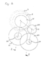
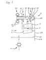
- This in FIGS. 1 to 3 illustrated transmission essentially comprises two gear stages 1, 2, which can be selectively switched via a synchronized transmission 3 in a drive train.
- the first gear stage 1 a conical-friction ring gear with two oppositely disposed cones 4, 5, which are arranged such that a gap 6 between the cones 4, 5 remains, in which a friction ring 7, the cone 5 runs encompassing.
- the cone 4 comprises a pressing device 8, which braces the two cones 4 and 5 between Verspannlagern 9, 10 while applying a variable contact pressure.
- the cone 4 on the one hand a tread 12 and on the other hand, a tensioning element 11, between which the pressing device 8 is effective, the pressing device 8 can move the clamping element 11 with respect to the tread 12 axially, so that the clamping element 11 on the one hand on the Verspannlager supports and on the other hand, the tread 12 presses against the friction ring 7, wherein this pressure is countered by the second cone 4 and the complementary bracing 10.
- the pressing device 8 comprises two disc springs 13, 14 and two pressing elements 15, 16 and two arranged between the pressing elements rolling elements 17.
- the plate springs 13, 14 and the contact pressure elements 15, 16 are arranged in series with respect to the contact pressure, so that the pressing element 15 remains over the prior art much greater range of motion with a change in torque, resulting in a more accurate and reproducible adjustment of the contact force.
- the plate spring 13 on radial recesses 18, 19, which engage in corresponding projections of the tread 12 having assembly or the pressing member 15.
- the plate spring 13 transmits torque between the Tread 12 having assembly and the pressing member 15, whereby the pressing member 15 is relieved of a torque-loaded sliding movement with respect to the tread 12 comprehensive assembly, which in turn leads to a higher reproducibility of the resulting torque-dependent contact force.
- the rolling elements 17 run in this embodiment in tracks of the respective pressing elements 15, 16, which have a variable depth. In this way, a torque-dependent distance between the pressing elements can be realized, wherein the rolling elements 17 ensure a high reproducibility of the resulting contact force when the pressing elements 15, 16 are displaced in the circumferential direction by an occurrence of the torque. It is self-evident that the abovementioned features can independently of one another advantageously ensure a reproducibility of the resulting contact pressure.
- a motor actuator for the pressing device which, as well as hydrodynamic or hydrostatic thrust bearing, is driven by measured torque to realize a torque-dependent contact force.
- FIGS. 1 to 5 illustrated embodiment further comprises with respect to the continuously variable conical friction ring 2 on the drive side a starting clutch, which is realized as a Trilokwandler.
- a starting clutch which is realized as a Trilokwandler.
- the latter differential gear part 23 is rigidly connected to the turbine wheel 22 with the one differential side 24, while the second differential side 25 is used from the output of this gear stage and is connected via a gear wheel 26 and to the gear 27 of a main output shaft 28 of the overall transmission comprising an output gear 33, on the other hand, the gear 27 meshes with the output 29 of the conical-friction-ring transmission part 1.
- the output gear 33 can mesh with, for example, the main differential of a motor vehicle.
- the differential gear part 23 comprises two friction clutches 30, 31 which can selectively fix the main input of the differential gear part 23 to the housing 32 or to the outlet 25. In this way, as can be seen immediately, the direction of rotation of the output can be changed, whereby a forward and a reverse gear can be easily realized.
- the clutches 30, 31 are open, the differential and the turbine wheel 22 ride freely, so that the conical friction ring transmission can be used despite the coupling of the power take-offs.
- both the drive cone 91 and the output cone 92 via a synchronization 94 to a main output shaft 95 can be switched, which in turn via a pinion 96 with the main differential 97 of a motor vehicle meshes.
- the drive cone 91 and the output cone 92 are connected to the main output shaft 95 with an identical number of reversals of rotation, so that a reversal of the direction of rotation can be ensured directly by the synchronization 94.
- This arrangement makes it possible with minimal number of modules, and thus in a very cost-effective manner to realize a forward and reverse gear.
- a reversal of direction can be effected here by meshing gears or revolving belt optionally only between one of the cones 91, 92 and the synchronization 94, so that optionally a first gear or an overdrive can be represented inexpensively by this arrangement.
- the pinions 91a and 92a and the wheels 91b and 92b may be connected via a belt arrangement or mesh directly.
- the synchronization is provided with a rest position or a middle position, so that the cones 91, 92 can run freely.
- the friction ring 93 or another coupling element can be adjusted even when the motor vehicle is at a standstill.
- FIG. 6 shown arrangement uses in particular the direction of rotation reversal of the conical-friction ring gear to provide cost-effective forward and reverse gear. It is thus suitable for all other, the direction of rotation reversing, continuously variable transmission.
- the drive train comprises a conical-friction-ring transmission 40, which, as in the exemplary embodiment according to FIGS. 1 to 5
- a power divider 41 and the output side a power divider 42 is assigned.
- a first gear 43 is connected in parallel to the conical-friction ring transmission 40 via the power dividers 41 and 42, this being synchronized on the drive side, as already described above are and can be switched via friction clutches 44, 45 optionally in the drive train between the drive 46 and output 47.
- FIG. 8 illustrated embodiment shows a coaxial arrangement of Anund output, which realized in a continuously variable transmission, in particular in a conical friction ring gear, advantageously a two-sided coaxial output.
- this leads to relatively low housing loads and, on the other hand, it is extremely compact, wherein preferably - and in particular in this exemplary embodiment - an output shaft 50 penetrates the drive cone 51 of a conical-friction ring transmission 52.
- This arrangement is also advantageous in other continuously variable transmission types, in particular in interaction with electric motors, wherein in the latter case the output shaft can also pierce the armature shaft of the electric motor.
- This is operatively connected via a pinion 56 with a driven gear 57, which sits on the output shaft 50.
- FIG. 9 A similar structure has the in FIG. 9 shown gear, the housing 60 is attached to a housing 61 of an electric motor. Also in this embodiment, the armature shaft 53 is hollow and is pierced by the output shaft 50. However, the output gear 56 meshes with a drive wheel 58 of a differential 59, which in turn is connected to the two-part drive shaft 50. Since a gear must be provided at this point anyway, this arrangement is extremely compact.
- this arrangement has a complementary planetary gear 62 for torque reduction between the engine and continuously variable transmission in order not to overload the continuously variable transmission.
- conical friction ring assembly 80 may in particular in conjunction with the arrangements according to FIGS. 7 . 8th and 9 come to apply and realize in a very compact manner a reverse gear
- said gear 80 includes two cones 81 and 82, which interact via a ring 83 with each other.
- the cone 82 has in addition to a normal cone area (D) on an oppositely circulating area (R), which in this Embodiment is implemented by a conical ring 84 which rotates about planetary 85, which in turn are fixedly mounted in the gear housing 86 and roll with their inner sides on a conical shaft 87 of the cone 82. In this way, the cone ring 84 rotates in the opposite direction to the remaining part of the cone 82.
- the cone 82 has a neutral region (N), which comprises a ring 88, which in turn is freely rotatably mounted on the cone shaft 87.
- the friction ring 83 from the major portion (D) of the cone 82 can first be displaced to the neutral region (N) with the conical ring 88 conforming to the rotation given by the main cone 82 and the friction ring 83.
- the friction ring 83 is displaced further toward the backward-running area (R), it leaves the main area (D), so that the rotation direction of the neutral area (N) can be adapted to the rotational direction of the backward-running ring 84. In this way, a very compact reverse gear is realized.
- Such a reverse gear 80 or even an arrangement designed in a known manner for reversing the direction of rotation, can in particular with the in FIG. 7 be shown embodiment, since, if the power and / or speed divider or adder 41 and 42 suitably connected and the gear ratios are selected appropriately, a stoppage of the output shaft 47 can be realized, although the conical friction ring gear 40 and the shaft 43rd rotate. In this way, in a vehicle all driving situations, ie reverse drive, forward drive and standstill, seamlessly without further clutches can be realized, with additional driving situations, such as full load or continuous load mode clutches or other gear stages may well be provided.
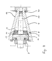
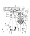
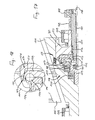
- FIGS. 11 to 18 illustrated arrangement which is essentially according to the arrangement FIGS. 1 to 5 corresponds, so that is dispensed with repeated explanations, two gear trains 101, 102 are provided, which can be selectively switched via a synchronized gearbox 123 and a cone clutch 134 in a drive train.
- the first gear train 101 in turn, a conical friction ring gear with two oppositely disposed cones 104, 105, which are arranged such that a gap 6 between the cones 104, 105 remains, in which a friction ring 107, the cone 105 runs encompassing.
- the cone 104 comprises a Pressing device 108, which clamps the two cones 104 and 105 in known manner or prescribed manner between Verspannlagern 109, 110 while applying a variable contact pressure.
- the pressing device on two rolling elements 117 and guide body 118 and 119, which are braced via disc springs 120 and over which, as will be explained below, a torque-dependent contact force is applied by the pressing device 108 expands depending on the torque and against the Bearings 109, 110 supported accordingly.
- the reverse gear includes a drive wheel 124, with which the transmission line 102 is branched off from the main transmission line. Via intermediate wheels 130 and 133, a ratchet wheel 125 is driven, which can be coupled via the synchronized gearbox 123 with the pinion 126, which in turn meshes directly with the outer wheel 127 of the main differential 115.
- the overall arrangement is extremely compact and can be made even more compact when the drive wheel 124 is connected via a synchronized transmission with the drive shaft 121 and meshes directly with the outer wheel 127.
- the arrangement comprises a forward gear, which is realized by the continuously variable transmission 101.
- the forward gear is coupled via the pinion 129 with the outer wheel 127 and thus with the reverse gear 102 and can be switched on and off via the clutch 134.
- the respective gear members of the sub-gear trains 101 and 102 also move freely when disengaged.
- the pressing device 108 works together with the clutch 134.
- the mode of action is based on the FIGS. 15 to 18 most comprehensible.
- the pressing device 108 may expand in dependence on the transmitted torque. This shows FIG. 15 the arrangement with a high torque and thus at high contact pressures and FIG. 16 the arrangement at low contact forces.
- the torque-dependent pressing force is generated by the fact that the support body 119 is supported on the bracing bearing 109 via a counter body 150 and via an output shaft 151. On the shaft 151 and the output gear 129 is seated.
- the shaft 151 via a needle bearing 152 on a centering 153 stored radially. From the output cone 104 is via a toothing 154 (see FIG. 18 ) and 155 torque transmitted to the output gear 129.
- the pressing device 108 In the pressing device 108, these torques cause a displacement of the balls 117, so that the pressing force can be varied as desired, as in FIGS. 15 and 16 seen.
- the two bodies 119 and 150 are respectively above conical surfaces 156, 157 (see FIG. 18 ) to each other.
- the two conical surfaces 156, 157 form the effective coupling 134, which is closed by the pressing device 108.
- the overall arrangement has a housing fixed cylinder 158, in which a piston 159 runs, which is acted upon via a hydraulic line 160 with a pressure.
- the piston 159 is mounted on the support body 119 via a thrust bearing 161 and a support body 162.
- the piston 159 when the piston 159 is pressurized, it relieves the body 150 of the clutch 134 of the contact pressure of the pressing device 108. As the clutch 134 opens, no more torque is transmitted, so that the pressing device 108 relaxes, it must therefore only a very low pressure can be applied to open the clutch 134 and keep it open. When the clutch 134 is open, a gap 163, as shown, remains between the conical surfaces 156, 157 FIG. 18 seen. It is understood that instead of the piston 159 and the hydraulic 160, other measures can be provided by which the body 119 relieved and the clutch 134 can be opened. Particularly suitable is any measure with which the body 119, bypassing the clutch 134 on the housing of the entire transmission can be supported.
- FIGS. 15 to 18 shown arrangement is particularly characterized by the fact that the piston 159 does not rotate, so that a relatively inexpensive seal can be done.
- the arrangement has the particular advantage that no additional devices are needed to close the clutch.
- the closing forces are dependent on the transmitted torque and increase with this, since the pressing device in this regard is equipped accordingly anyway.
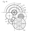
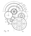
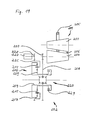
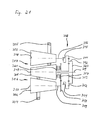
- the in the Figures 19 and 20 The arrangements shown are each comprised of a conical friction ring gear 201 and a reverse gear 202 connected in series therewith.
- the conical friction ring gears 2011 are basically identical in construction and each have an input cone 203 and an output cone 204 axially parallel, facing one another and between which a friction ring 205 is displaceable in a gap 206, so that depending on the position of the friction ring 205, a variable transmission ratio can be adjusted.
- the friction ring 205 surrounds the drive cone 203 in these embodiments, while the output cone 204 carries an output pinion 207. It is understood that depending on the specific embodiment, the conical friction ring gear can also be designed differently.
- the output pinion 207 meshes directly with an assembly 208 which carries the sun gear 209 of a planetary gear 210.
- FIG. 20 illustrated arrangement includes a planetary gear 211 with a sun gear 212 which is driven by the output gear 207. This is done via a belt 213 and a sun gear 212 revolving wheel 214.
- a belt 213 all known belt or chain arrangements, by which a sufficiently reliable power transmission can be permanently ensured, are used.
- Both planetary gears 210 and 211 each have planet gears 215 and 216, respectively, which mesh on the one hand with the respective sun gear 209 and 212 and on the other hand with a respective outer wheel 217 and 218, respectively.
- the outer wheel 217 is directly connected to the circumferential frame 219 of a differential 220.
- the planetary gear 210 and thus the reverse gear 202 directly on the differential 220 This arrangement proves to be extremely compact in their construction and extremely high in their efficiency, because the number of gear members in the drive train is minimized.
- a reverse gear 202 arranged directly on the differential 220 is also advantageous, independently of the other features of the present invention, because of its compact design.
- the outer wheel 218 is connected to a driven gear 221 and revolves with it, which in turn meshes with the orbiting frame 222 of a differential 223.
- the consequent reversal is compensated by the belt assembly 213, wherein in the embodiment according to FIG. 20 the reverse gear is disposed on or about an intermediate shaft 224.
- An arrangement on the intermediate shaft 224 has opposite to in FIG. 19 proposed arrangement directly on the differential 220 has the advantage that the overall arrangement after FIG. 20 more flexible in their spatial arrangement can be configured. This is particularly advantageous for environments in which the spatial relationships are limited directly in the vicinity of the differential by third modules.
- the arrangement of the reverse gear on an intermediate shaft 224 - in particular also because of the rotation direction change caused thereby - also independent of the other features of the present invention is advantageous.
- the latter applies in particular when conical friction ring gears are to be used in conjunction with foreign motors which have an opposite direction of rotation.
- the belt assembly 213 may be dispensed with and the pinion 207 meshed with the collar 214.
- the output cone 204 is arranged directly on the shaft 224, so that a separate output pinion 207 and the belt arrangement 213 can be dispensed with in their entirety.
- the drive from the conical friction ring gear 201 can take place via the outer wheels 217 or 218 or via other gear elements of the reverse gear, instead of via the sun gears 209 or 212.
- the sun gears or other gear members can be used for this purpose.
- each fixing systems are provided with which a gear member and that in these embodiments, a planetary with the planet frame 225 and 226, on which the planet 215 and 216 stored are rigidly fixable. Furthermore, locking systems are available, which allow fixing two gear members of the respective planetary gear 210 and 211 with each other. This will be in the embodiment after FIG. 19 Sun gear 209 and outer wheel 217 and in the embodiment according to FIG. 20 Outer gear 218 and encircling frame 226 of the planet 216 optionally set together.
- various fixing systems such as clutches, brakes or synchronization synchronization can be used. Of these three are provided by way of example in the illustrated embodiments, which, depending on the specific requirements, can be easily replaced.
- the frame 225 of the planet 215 is fixed by means of an electromagnetic brake 227, which can selectively brake a brake pinion 228, which in turn meshes with the frame 225 of the planet 215.
- the brake is activated, so that as the frame 225 is slowed down relative to the sun gear 209 and the outer wheel 217, the drive or speed of the output decreases until it finally stops comes and then the direction changes.
- the optional setting is effected via a synchronization 230, by means of which the frame 226 carrying and revolving with this frame 226 can optionally be synchronized with the outer wheel 218 or with respect to a fixed wheel 231, which is fixed to the housing 232 in this embodiment.
- the mechanisms occurring here correspond to the mechanisms already described in the exemplary embodiment FIG. 19 it will be appreciated that the rack 226 may be synchronized with the sun gear 212 rather than with the outer wheel 218.
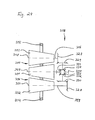
- This in FIG. 21 continuously variable transmission shown has an input cone 301 and two output cone 302, 303, which are each coupled to the input cone 301 via about the respective output cone 302, 303 rotating friction rings 304, 305.
- the friction rings 304, 305 By displacing the friction rings 304, 305 along the gaps remaining between the cones 301, 302, 303, the partial transmissions 306 and 307 formed by the cones 301 and 302 or 301 and 303 can be adjusted continuously.
- the two partial transmissions 306, 307 and the two output cones 302, 303 are connected via an aggregate transmission 308 to an output shaft 309.
- the outer gear 311 is fixedly connected to a further ring 314, which in turn meshes with a pinion 315, which is arranged on the output shaft 316 of the cone 303
- the sun gear 313 is fixedly connected to a wheel 317 and revolves with this, which in turn meshes with a pinion 318, which is arranged on the output shaft 319 of the cone 302.
- the planet gears 312 are further supported in a frame 320, which is connected to the output shaft 309 and rotates together with the output shaft 309 and the planetary gears 312.
- a summation gear 308 is provided in which the rotational speeds of the pinions 315, 318 and the driven cones 302, 303 depending on the gear ratio and position of the friction rings 304, 305 are summed up to the total rotational speed of the shaft 309.
- the transmission ratios are selected such that at identical position of the friction rings 304, 305, ie the same rotational speed of the two output cone 302, 303, the planet gears 312 stand in their own rotation in the frame 320 and rotate only together with the outer rim 311 and the sun gear 313 , In this way, losses can be minimized, especially in continuous operation.
- For loss minimization also serves a clutch 321, with which the output shaft 309 can be connected directly or, according to specific embodiment via a transmission gear, with the drive cone 301, so that in particular at high and relatively uniform speeds, in which the benefits of a continuously variable transmission can not be used anyway and such continuously variable transmission lead to unnecessary losses, the two partial transmission 306, 307 can be bridged.
- the summation gear 308 adds up the rotational speeds of the two cones 302, 303 and otherwise serves as a torque balance for the torques occurring at this cone 302, 303.
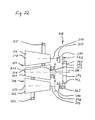
- FIG. 22 illustrated embodiment substantially corresponds to the embodiment according to FIG. 21 , so that identical acting assemblies are also numbered identically and is waived a repetition of the identical functionalities.
- a locking coupling 322 by means of which the rotating frame 320 of the planet gears 312 can be fixed to the outer rim 311, and on the other hand, a clutch 323, by means of which the frame 320 and the output shaft 309 can be fixed to a non-illustrated, stationary clutch housing , on.
- the first clutch 322 serves to force the rotation of the planet gears 312 in self-rotation in given operating conditions, so that losses are avoided by the planet gears 312 and the housing 320 and the shaft 309 rotate together with the outer rim 311 and the sun gear 313.
- Second clutch 323 serves to hold planetary gears 312 stationary but rotatable about their own axes. This arrangement is provided in particular for interaction with a transmission, in which the transmission is designed such that the outer ring and the sun gear 313 can also rotate in opposite directions or rotate in opposite directions. This can be realized for example by an additional, intermediate gear or by a separate reverse gear in the transmission line between at least one of the partial transmission 306, 307 and the summation 308.
- the summation gear 308 can be controlled via the two partial transmissions 306, 307 such that a rotational speed of 0 results on the shaft 309, although the drive bevel 301 rotates.
- the clutch 323 can be used to set the transmission.
- a starting of the output shaft 309 only by adjusting the friction rings 304, 305 or by adjusting the partial transmission 306, 307 possible.
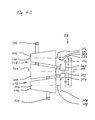
- FIG. 23 The arrangement shown corresponds essentially to the arrangement according to FIG. 21 , In this respect, the partial transmissions 306, 307 are identical in both arrangements. Only the summing gear 308 is in the arrangement after FIG. 23 designed differently than this in the arrangement according to FIG. 21 the case is. For this reason, a detailed explanation of the matching components and their mode of operation is also omitted here.
- the output shaft 309 is directly connected to an outer rim 324 of a planetary gear and runs together with this.
- the planet gears 312 are mounted in a frame 325 which can rotate together with the planetary gears 312 and a wheel 326, wherein the wheel 326 meshes with the pinion 315 on the output shaft 306 of the cone 303.
- transmission 308 thus acts as a summation gear and adds or subtracts the rotational speeds of the two partial transmissions 306, 307th
- FIG. 24 shown arrangement corresponds with respect to their partial transmission 306, 307 the arrangements that in the FIGS. 21 to 23 are shown.
- the transmission 308 is configured differently.
- the summation gear 308 via bevel gears 327 and 328, which are respectively arranged on the output shafts 316 and 319 of the cones 303 and 302, driven.
- the bevel gears 327 and 328 mesh with bevel gears 329 and 330, which in turn are connected to the stationary about its own axis rotating bevel gears 331 and 332 of the differential.
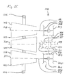
- the embodiment according to FIG. 25 corresponds in its basic structure according to the embodiment FIG. 24 so that here also the summation gear 308 essentially by a differential 335, which drives the output shaft 309 with a driven gear 336 via a bevel gear 337, is formed.
- the output gear 336 meshes with a bevel gear 338, which in turn can be connected via a synchronized clutch 339 with the drive cone 301, so that the two partial transmissions 306, 307 can be bridged as needed.
- the clutches 340 and 341 can thus easily change the effective direction of rotation of the partial transmission 306, 307, so that the transmission after FIG. 25 has a very versatile transmission behavior.
- the partial transmissions 306, 307 defined by the respective conical axes 348, 349, 350, which are respectively aligned parallel to one another, have partial transmission planes, all of which lie in the plane of the drawing.
- these gears build extremely flat and are particularly suitable for use in trucks or small trucks, as they may be provided for example below a cargo area. This suitability is all the more because the transmission according to the invention by the use of two partial transmissions even at higher torques, as applied by modern diesel engines, work with good efficiency, because extremely high contact forces can be avoided by the use of two partial transmissions.
- the characteristic of the overall transmission can be significantly influenced by the choice of directions of rotation, with which the partial transmissions 306, 307 act on the summation gear 308.
- reverse gears or the direction of rotation changing gear parts of Advantage is in FIG. 10 exemplified for the above already partial transmission 80
- FIGS. 1 . 4 . 8th and 9 and 14 to 17 removed, the continuously variable transmission shown there, in the direction of their bearings each sealed by seals 70 (only exemplified) sealed.
- seals 70 only exemplified
- a separate fluid space in which the cones and the coupling member are arranged a "silicone oil" is preferably used as the fluid in which preferably about 10 to 30 mol% of the methyl groups in polydimethylsiloxane are replaced by phenyl groups and its viscosity at 25 ° C is about 200 mm 2 / s.
- any other fluid could be used which is stabilized with respect to its temperature dependence of the physical and chemical parameters against the temperature dependence of mineral oils and / or with regard to the temperature-dependent compression gradient or the temperature-dependent viscosity gradient between the gradients of mineral oils and the gradients of silicone oil.
- FIG. 26 The temperature dependence of exemplary fluids or fluids described above is in FIG. 26 in logarithmic form, with one dashed line 89a representing mineral oils and the other dashed line 89b representing silicone oil.
- These fluids ensure under operating conditions that a gap between the cones 4, 5; 51, 55, 81, 82, 91, 92, 104, 105, 203, 204, 301, 302, 303 and the coupling links 7; 54, 83, 93, 107, 205, 304, 305, which is bridged by the fluid.
- this gap can be detected, for example, in the case of metallic components by electrical voltage measurements, it being determined experimentally that this gap is formed only after a few revolutions, ie when the fluid is distributed, so that the compressibility and the viscosity are suitably selected with respect to the gap dimension should be.
- the bracing or pressing devices are dimensioned such that a corresponding gap is maintained under operating conditions.
- the tread 12 of both cones is preferably configured axially different. In the case of present exemplary embodiments, this is realized by grooves of different widths (not shown). Alternatively, an axially varying surface roughness or the like may be provided.
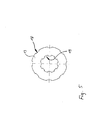
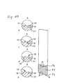
- the surface of the friction ring 7; 54, 83, 93, 107, 205, 304, 305 are provided with grooves for controlling the shearing force of the liquid in the remaining gaps between the cones 4, 5; 51, 55, 81, 82, 91, 92, 104, 105, 203, 204, 301, 302, 303 and the friction ring 7; 54, 83, 93, 107, 205, 304, 305, as exemplified in FIG. 27 illustrated by a friction ring 71.
- the friction ring 71 has two circumferential surfaces 72, 73, each, as based on the friction rings 7; 54 explained with the surfaces of cones 4, 5; 51, 55, 81, 82, 91, 92, 104, 105, 203, 204, 301, 302, 303 interact.
- the surfaces 72, 73 may in this case have different surface configurations.
- trapezoidal webs 74 see FIG. Fig. 27b
- rounded groove inlets cf. FIGS. 27b and 27c ), whereby edging into an opposite surface can be avoided.
- Such rounded groove inlets 75 also seem to be advantageous for the distribution of the oil film or the surface pressure.
- Rounded groove bases (76, cf. FIGS. 27b, 27c and 27d ), however, can avoid notch effects under load in the groove bottoms.
- substantially cuboid webs 77 (see FIG. Fig. 27c ) be provided.
- the webs 78 come with round cross-sectional outer curves 79 are used.
- Such grooves can be provided identically or differently on the cones as well as, depending on the specific embodiment, on the friction-ring surfaces.
- the distribution of the grooves or webs over a surface, in particular in the axial direction vary.
- the surface pressure or surface pressure distribution can also be varied along a cone or suitably adjusted and / or adapted to the oil film thickness.
- the groove cross section determines this probably the outflow of oil from the contact zone of the respective gear members.
- the friction ring preferably has a spherical cross section, so that in spite of the presence of a gap over a Hertzian pressure as large a contact surface can be realized.
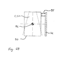
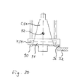
- the friction ring 7 54, 83, 93, 107, 205, 304 and 305 in present embodiments held in a known manner by a cage 90, on which a Verstell Georgia 91 runs and which is rotatably mounted about an axis 92, as in FIG. 28 shown.
- the adjusting bridge 91 can not run freely when the angle of the cage 90 is changed, but is forcibly guided via an actuator 93 on a spindle 94 rotatably mounted on the housing 32.
- end stops 96 (in Fig. 30 exemplified) against which the adjustment bridge 91 can accumulate, these end stops are arranged such that the ring 7, 54, 83, 93, 107, 205, 304, 305 aligned with respect to its axis of rotation parallel to the cone axes and thus not further emigrated. In this way, a total destruction of the transmission can be counteracted when the positioning of the ring fails.
- sensors which display a corresponding position of the adjusting bridge 91.
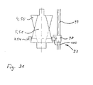
- FIG. 31 An alternative adjustment 97 shows Fig. 31 , this variant builds extremely inexpensive.
- the ring 7, 54, 83, 93, 107, 205, 304, 305 is guided on one side only by a holding device 98. This is provided on the inlet side, so that in the selected representation of the ring 7, 54, 83, 93, 107, 205, 304, 305 of the holding device 98 starting first the gap between the cones 4, 5; 51, 55, 81, 82, 91, 92, 104, 105, 203, 204, 301, 302, 303 and then passing the cone 5; 51, 81, 91, 105, 203, 302, 303 circulates before it reaches the holding device 98 again.
- the holding device 98 is mounted on a spindle 99 and comprises the ring with sufficient play, so that it can displace the angular position of its axis of rotation from the plane formed by the cone axes, whereby it performs a traveling movement and self-propelled movement of the holding device 98 follows.
- this can with a rotational degree of freedom in the plane of the FIG. 31 be provided with respect to the designed as a spindle adjusting 99 and lead the ring substantially free of play.
- the ring 7, 54, 83, 93, 107, 205, 304, 305 designed such that it has a torque perpendicular to its axis of rotation, so can only one side of a system 100
- the ring 7, 54, 83, 93rd , 107, 205, 304, 305 be provided leading holding device, which counteracts this torque and - depending on the desired displacement - away from the ring, so that this independently performs a rotational movement of its axis of rotation from the plane formed by the cone axes and begins to migrate until he reaches the guide, which aligns in again accordingly, or turns the axis of rotation of the ring by moving towards him so that he wanders away from the guide until it no longer follows him and he returns by his own torque Turn the axis back until it has reached the lead again.
- the latter arrangement allows the ring 7, 54, 83, 93, 107, 205, 304, 305 a particularly large amount of leeway, so that it can move in a very independent and self-stabilizing manner, whereby frictional losses can be minimized.
Landscapes
- Engineering & Computer Science (AREA)
- General Engineering & Computer Science (AREA)
- Mechanical Engineering (AREA)
- Friction Gearing (AREA)
- Transmission Devices (AREA)
- Lubricants (AREA)
- Developing Agents For Electrophotography (AREA)
- Retarders (AREA)
- General Details Of Gearings (AREA)
Claims (10)
- Engrenage planétaire à bagues de friction coniques (1,2 ;40 ;80 ;90 ;101 ;201) comportant une bague de friction (7 ;54 ;71 ;83 ;93 ;107 ;205 ;304 ;305) comme organe de couplage et comportant deux cônes (4, 5 ; 51, 55 ; 81, 82 ; 91, 92 ; 104, 105 ; 203, 204 ; 301, 302, 3 03) comme au moins deux organes d'engrenage planétaire, qui peuvent transmettre avec friction un couple de rotation, dans lequel au moins pendant le fonctionnement un interstice (6 ;106 ;206 ;306,307) rempli avec un liquide entre respectivement les cônes (4,5 ; 51, 55 ; 81, 82 ; 91, 92 ; 104, 105 ; 203, 204 ; 301, 302, 3 03) et la bague de friction (7 ; 54 ; 71 ; 83 ; 93 ; 107 ;205 ;304 305) est prévu, caractérisé en ce que au moins un des organes d'engrenage planétaire et/ou l'organe de couplage sont réticulés avec un liquide, dont la viscosité varia proportionnellement à un gradient de viscosité dépendant de la température, qui se situe entre le gradient de viscosité (89a) des huiles minérales et les gradients de viscosité (89) des diméthylsiloxanes.
- Engrenage planétaire à bagues de friction coniques (1,2 ; 40 ; 80 ; 90 ;101 ;201) comportant une bague de friction (7 ;54 ;71 ;83 ;93 ;107 ;205 ;304 ;305) comme organe de couplage et comportant deux cônes (4,5 ; 51, 55 ; 81, 82 ; 91, 92 ; 104, 105 ; 203, 204 ; 301, 302, 3 03) comme au moins deux organes d'engrenage planétaire, qui peuvent transmettre avec friction un couple de rotation, dans lequel au moins pendant le fonctionnement un interstice (6 ;106 ;206 ; 306, 307) rempli avec un liquide entre respectivement les cônes (4,5 ; 51, 55 ; 81, 82 ; 91, 92 ; 104, 105 ; 203, 204 ; 301, 302, 3 03) et la bague de friction (7 ;54 ;71 ;83 ;93 ;107 ;205 ;304 ; 305) est prévu, caractérisé en ce que au moins un des organes d'engrenage planétaire et/ou l'organe de couplage sont réticulés avec un liquide, dont la compressibilité varie proportionnellement à un gradient de compressibilité dépendant de la température, qui se situe entre le gradient de compressibilité des huiles minérales et les gradients de compressibilité des diméthylsiloxanes.
- Engrenage selon la revendication 1 ou 2, caractérisé en que le liquide comprend des méthylsiloxanes, diméthylphénylsiloxanes et/ou méthylphénylsiloxanes présnetant des groupes phényles, respectivement des γ- méthylsiloxanes trifluorpropyl substitués alkyl substitués.
- Engrenage selon la revendication 3, caractérisé en ce que le liquide comprend des polydiméthylsiloxanes, polydiméthyldiphénylsiloxanes et/ou polyméthylphénylsiloxanes présentant des groupes phényles, respectivement trifluorpropyl substitués alkyl substitués.
- Engrenage selon une des revendications 1 à 4, caractérisé en ce que le liquide présente des composants avec des substituts organiques.
- Engrenage selon une des revendications 1 à 5, caractérisé en ce que la viscosité du liquide est stabilisée en ce qui concerne la température.
- Engrenage selon une des revendications 1 à 6, caractérisé en ce que les surfaces de roulement d'au moins un organe d'engrenage planétaire présentent des surfaces différentes (72,73).
- Engrenage selon la revendication 7, caractérisé en ce que, axialement le long d'au moins un des organes d'engrenage planétaire (4,5) des rainures ou protubérances de largeurs différentes, respectivement une structure de surface ou un traitement de surface variable sont prévus.
- Engrenage selon une des revendications 1 à 8, caractérisé en ce que l'organe de couplage (7) présente au moins une surface de roulement avec une surface structurée (72,73), notamment au moins une surface de roulement avec des rainures.
- Engrenage selon une des revendications 1 à 9, caractérisé en ce que l'organe de couplage (7) présente notamment en collaboration avec un liquide réticulant la surface de roulement de l'organe de couplage (7), respectivement la surface de roulement correspondante de l'organe d'engrenage correspondant et/ou en collaboration avec un support d'un côté de l'organe de couplage (7) au moins une surface de roulement avec une section transversale s'écartant d'une ligne droite, de préférence avec une section transversale conclave ou bombée.
Applications Claiming Priority (13)
| Application Number | Priority Date | Filing Date | Title |
|---|---|---|---|
| DE10245897 | 2002-09-30 | ||
| DE10245897 | 2002-09-30 | ||
| DE10246655 | 2002-10-07 | ||
| DE10246655 | 2002-10-07 | ||
| DE10303891 | 2003-01-30 | ||
| DE10303896 | 2003-01-30 | ||
| DE10303891A DE10303891A1 (de) | 2002-09-30 | 2003-01-30 | Getriebe |
| DE10303896A DE10303896A1 (de) | 2002-09-30 | 2003-01-30 | Umlaufendes Getriebe |
| DE10304094 | 2003-01-31 | ||
| DE10304094 | 2003-01-31 | ||
| DE10323109 | 2003-05-20 | ||
| DE10323109 | 2003-05-20 | ||
| PCT/DE2003/003254 WO2004031615A2 (fr) | 2002-09-30 | 2003-09-29 | Engrenage planetaire |
Publications (2)
| Publication Number | Publication Date |
|---|---|
| EP1546578A2 EP1546578A2 (fr) | 2005-06-29 |
| EP1546578B1 true EP1546578B1 (fr) | 2014-11-19 |
Family
ID=52433687
Family Applications (1)
| Application Number | Title | Priority Date | Filing Date |
|---|---|---|---|
| EP03756445.7A Expired - Lifetime EP1546578B1 (fr) | 2002-09-30 | 2003-09-29 | Engrenage planetaire |
Country Status (7)
| Country | Link |
|---|---|
| US (2) | US7559868B2 (fr) |
| EP (1) | EP1546578B1 (fr) |
| JP (1) | JP4988198B2 (fr) |
| AU (1) | AU2003299146A1 (fr) |
| BR (1) | BRPI0307387B1 (fr) |
| ES (1) | ES2528176T3 (fr) |
| WO (1) | WO2004031615A2 (fr) |
Families Citing this family (15)
| Publication number | Priority date | Publication date | Assignee | Title |
|---|---|---|---|---|
| DE102007002581A1 (de) * | 2006-09-22 | 2008-04-03 | Rohs, Ulrich, Dr. Ing. | Kegelreibringgetriebe |
| ES2384562T3 (es) * | 2007-02-26 | 2012-07-09 | Rohs, Ulrich | Disposición de accionamiento con un engranaje parcial regulable sin escalonamiento |
| EP2215380B1 (fr) * | 2007-11-27 | 2011-05-25 | Rohs, Ulrich | Transmission avec éléments coniques et anneau de friction |
| KR101181748B1 (ko) * | 2010-03-18 | 2012-09-11 | 현대 파워텍 주식회사 | 콘 링 타입 무단변속기 |
| US8574110B2 (en) * | 2010-08-02 | 2013-11-05 | Ford Global Technologies, Llc | Transmission producing stepless variable speed ratios |
| JP2012062935A (ja) * | 2010-09-15 | 2012-03-29 | Ud Trucks Corp | 無段変速機 |
| DE102011013070A1 (de) * | 2011-03-04 | 2012-09-06 | Ulrich Rohs | Kegelreibringgetriebe |
| KR101272935B1 (ko) * | 2012-03-12 | 2013-06-11 | 현대자동차주식회사 | 차량의 자동화 수동 변속기 |
| KR101360431B1 (ko) * | 2012-09-04 | 2014-02-11 | 현대 파워텍 주식회사 | 무단변속기 |
| US20150362049A1 (en) * | 2013-01-18 | 2015-12-17 | Jatco Ltd | Multi-disc transmission |
| US10221927B2 (en) | 2014-08-14 | 2019-03-05 | Ford Global Technologies, Llc | Continuously variable transmission with overdrive |
| DE102014013468A1 (de) | 2014-09-17 | 2016-03-17 | Ulrich Rohs | Kegelreibringgetriebe und Verfahren zum Betrieb eines Kegelreibringgetriebes |
| DE102015200798B3 (de) * | 2015-01-20 | 2016-06-16 | Schaeffler Technologies AG & Co. KG | Getriebeanordnung für einen Elektromotor eines Fahrzeugs sowie Fahrzeug mit der Getriebeanordnung |
| US9970521B1 (en) | 2016-02-26 | 2018-05-15 | Rodney J. Cook and successors in trust | Infinitely variable transmission |
| US11772743B2 (en) * | 2022-02-18 | 2023-10-03 | Joseph Francis Keenan | System and method for bicycle transmission |
Family Cites Families (97)
| Publication number | Priority date | Publication date | Assignee | Title |
|---|---|---|---|---|
| US299231A (en) * | 1884-05-27 | Device for transmitting motion | ||
| US1709346A (en) * | 1929-04-16 | garrard | ||
| US1069182A (en) * | 1912-12-13 | 1913-08-05 | Remy Brothers Company | Differential speed-changing mechanism. |
| US1637664A (en) * | 1924-02-02 | 1927-08-02 | Stoeckicht Wilhelm | Change-speed friction gearing |
| FR615659A (fr) | 1926-05-05 | 1927-01-13 | Changement de vitesses continu et automatique | |
| GB298676A (en) | 1927-07-15 | 1928-10-15 | Charles George Garrard | Improvements in and relating to variable speed gearing |
| US1868676A (en) * | 1929-05-03 | 1932-07-26 | Stoeckicht Wilhelm | Friction roller gearing |
| GB343225A (en) | 1929-12-09 | 1931-02-19 | Herbert Reed Hall | Improvements in and relating to speed gears of the infinitely variable type |
| US2073157A (en) * | 1936-04-20 | 1937-03-09 | Rex Hide Inc | Wiper blade fastener |
| DE745147C (de) | 1939-04-28 | 1944-02-28 | Aeg | Getriebe mit Rastkupplung |
| US2545152A (en) * | 1947-07-16 | 1951-03-13 | Ebauches Sa | Infinitely variable speed gear |
| US2583790A (en) * | 1948-11-10 | 1952-01-29 | Westinghouse Electric Corp | Frictional gear mechanism |
| US2743621A (en) * | 1949-11-02 | 1956-05-01 | Beier Josef | Infinitely variable friction wheel gears |
| CH290407A (de) * | 1950-09-20 | 1953-04-30 | Ag Dabo | Mechanisches stufenloses Wechselgetriebe. |
| US3048046A (en) * | 1960-04-11 | 1962-08-07 | Algar H Cosby | Power transmission for variable speed and torque |
| US3026736A (en) * | 1960-12-06 | 1962-03-27 | Friedrich Cavallo Getriebe Und | Ball transmission unit |
| FR1299074A (fr) * | 1961-06-08 | 1962-07-20 | G Ab | Variateur de vitesses à frictions multiples |
| US3375733A (en) * | 1966-01-10 | 1968-04-02 | Deere & Co | Combined variable speed and planetary drive |
| US3347106A (en) * | 1967-02-14 | 1967-10-17 | Metallurg De Saint Urbain Atel | Device having a friction drive between two surfaces in a liquid |
| USRE27211E (en) * | 1969-10-15 | 1971-11-02 | Friction drive fluid | |
| US3677109A (en) * | 1971-01-14 | 1972-07-18 | Gates Rubber Co | Continuously variable friction gear |
| DE2336337A1 (de) | 1973-07-17 | 1975-01-30 | Neuweg Fertigung Gmbh | Hydraulisch unterstuetzter mechanischer anpresskraftregler fuer stufenlos einstellbare waelzgetriebe |
| CA1070664A (fr) * | 1974-09-16 | 1980-01-29 | Marvin F. Smith (Jr.) | Additifs ameliorants l'indice de viscosite d'huiles de graissage |
| DE2621682A1 (de) * | 1976-05-15 | 1977-11-24 | Zahnradfabrik Friedrichshafen | Stufenlos verstellbares kegelscheiben-umschlingungsgetriebe |
| GB1499019A (en) * | 1976-08-16 | 1978-01-25 | United Lubricants Ltd | Liquid coolant composition |
| US4238976A (en) * | 1978-10-19 | 1980-12-16 | Vadetec Corporation | Infinitely variable power transmission and system |
| US4382188A (en) * | 1981-02-17 | 1983-05-03 | Lockheed Corporation | Dual-range drive configurations for synchronous and induction generators |
| US4449415A (en) * | 1981-09-23 | 1984-05-22 | Dow Corning Corporation | Traction fluid and traction drive system containing said fluid |
| WO1983003291A1 (fr) * | 1982-03-15 | 1983-09-29 | Chambers, Robert, O. | Jeu de roues d'engrenage ayant un mecanisme interne d'engrenage |
| JPS5965659A (ja) | 1982-10-04 | 1984-04-13 | Nissan Motor Co Ltd | 動力伝達装置 |
| DE3241789C2 (de) * | 1982-11-11 | 1985-08-08 | Ford-Werke AG, 5000 Köln | Getriebeaggregat für Fahrzeuge, insbesondere für Kraftfahrzeuge mit Frontantrieb |
| JPS60116959A (ja) * | 1983-11-28 | 1985-06-24 | Toyota Central Res & Dev Lab Inc | 車輛用無段変速装置 |
| US4577523A (en) * | 1983-11-28 | 1986-03-25 | Dow Corning Corporation | Silicone traction fluids |
| GB8412855D0 (en) | 1984-05-19 | 1984-06-27 | Stidworthy F M | Self-regulating transmission |
| GB2180020A (en) | 1985-09-03 | 1987-03-18 | Ford Motor Co | Continuously variable transmission combining chain and V-belt drives with hydrokinetic torque converter |
| JPS62184270A (ja) * | 1986-02-07 | 1987-08-12 | Toyota Central Res & Dev Lab Inc | ベルト駆動式無段変速機 |
| SU1557395A2 (ru) | 1986-07-14 | 1990-04-15 | И.Г.Мухин, А И.Мухин, Н„И.Кузевич, 0,Н.Мухина и В.В.Кузевич | Вариатор И.Г.Мухина |
| JPH01105057A (ja) | 1987-10-14 | 1989-04-21 | Kubota Ltd | 摩擦式無段変速装置 |
| DE3835052A1 (de) | 1987-10-21 | 1989-05-03 | Barmag Barmer Maschf | Reibkoerpergetriebe |
| EP0321621B1 (fr) | 1987-12-23 | 1993-03-24 | Honda Giken Kogyo Kabushiki Kaisha | Transmission continue de vitesse pour véhicules automobiles |
| US4955852A (en) * | 1988-07-07 | 1990-09-11 | Toyota Jidosha Kabushiki Kaisha | Planetary gear mechanism having means for accurate alignment of sun gear |
| JPH0272262A (ja) * | 1988-09-07 | 1990-03-12 | Toyota Motor Corp | ベルト式無断変速機用プーリ |
| JPH06100257B2 (ja) * | 1989-09-04 | 1994-12-12 | バンドー化学株式会社 | 無段変速装置 |
| US5073157A (en) | 1990-02-20 | 1991-12-17 | Power Engineering & Manufacturing, Ltd. | Mechanically variable transmission |
| US5069078A (en) * | 1990-07-30 | 1991-12-03 | Fairbanks Everitt E | Transmission mechanism |
| BE1004806A3 (nl) * | 1990-11-22 | 1993-02-02 | Volvo Car Sint Truiden Nv | Inrichting voor het regelen van een continu variabele transmissie bij motorvoertuigen. |
| US5213011A (en) * | 1991-04-05 | 1993-05-25 | Mazda Motor Corporation | Power transmission device for vehicle |
| DE4202200A1 (de) | 1992-01-28 | 1993-07-29 | Fichtel & Sachs Ag | Anordnung zur betaetigung einer reibungskupplung eines von einer brennkraftmaschine angetriebenen kraftfahrzeuges |
| DE4204200A1 (de) * | 1992-02-13 | 1993-08-19 | Daimler Benz Ag | Fluessigkeit und deren verwendung |
| JPH05340456A (ja) * | 1992-06-08 | 1993-12-21 | Nippon Seiko Kk | 動力伝達装置 |
| RU2079017C1 (ru) | 1992-06-18 | 1997-05-10 | Новосибирский государственный технический университет | Фрикционная муфта |
| JPH06174036A (ja) | 1992-11-30 | 1994-06-21 | Isuzu Motors Ltd | トロイダル型無段変速機 |
| JP3569537B2 (ja) * | 1993-09-30 | 2004-09-22 | Ntn株式会社 | 摩擦伝動機構 |
| IN189939B (fr) * | 1993-12-20 | 2003-05-17 | Torotrak Dev Ltd | |
| DE4445017A1 (de) * | 1994-03-12 | 1995-09-14 | Kupplungstechnik Gmbh | Überlastkupplung |
| DE69617289T2 (de) | 1995-02-27 | 2002-07-18 | Isuzu Motors Ltd., Tokio/Tokyo | Stufenloses Toroidgetriebe |
| DE19607812A1 (de) | 1995-03-21 | 1996-09-26 | Luk Getriebe Systeme Gmbh | Stufenlos einstellbares Getriebe |
| DE19525068A1 (de) * | 1995-07-10 | 1997-01-16 | Wacker Chemie Gmbh | Beschichtungsmassen auf Basis von in Wasser redispergierbaren, wasserlösliches Polymer und Organosiliciumverbindung enthaltenden Pulvern |
| DE59604908D1 (de) * | 1995-10-26 | 2000-05-11 | Getrag Innovations Gmbh | Kraftfahrzeuggetriebe mit stufenlos veränderbarem übersetzungsverhältnis |
| FR2741128A1 (fr) | 1995-11-09 | 1997-05-16 | Crasset Dominique | Perfectionnements aux dispositifs d'actionnement de systemes tels que les embrayages ou les boites de vitesses |
| DE19542726B4 (de) | 1995-11-16 | 2006-02-16 | Rohs, Ulrich, Dr.-Ing. | Kegelreibringgetriebe |
| JPH10205600A (ja) * | 1997-01-21 | 1998-08-04 | Nissan Motor Co Ltd | トロイダル式無段変速機用転動体構造及びトロイダル式無段変速機用転動体構造表面被膜の形成方法並びにトロイダル式無段変速機用潤滑組成物 |
| DE19717290A1 (de) | 1997-04-24 | 1998-10-29 | Claas Usines France | Vorrichtung zur Drehmomentmessung |
| JP4128636B2 (ja) * | 1997-05-19 | 2008-07-30 | ウルリッヒ・ロース | 円錐摩擦リング式変速機および円錐摩擦リング式変速機の摩擦リング制御のための方法 |
| US5924953A (en) * | 1997-05-21 | 1999-07-20 | Rohs; Ulrich | Friction cone gearing |
| DE19909347B4 (de) * | 1998-03-10 | 2012-03-29 | Schaeffler Technologies Gmbh & Co. Kg | Getriebe |
| JP3956475B2 (ja) | 1998-03-13 | 2007-08-08 | 日本精工株式会社 | トロイダル型無段変速機 |
| DE69802069T2 (de) * | 1998-04-24 | 2002-07-04 | Van Doorne's Transmissie B.V., Tilburg | Kraftfahrzeugantriebseinheit |
| DE19837368A1 (de) * | 1998-08-18 | 2000-02-24 | Ulrich Rohs | Kegelreibringgetriebe und Verfahren zur Regelung des Übersetzungsverhältnisses bei einem Kegelgetriebe |
| JP2000120822A (ja) * | 1998-10-21 | 2000-04-28 | Nsk Ltd | 無段変速装置 |
| JP2000130531A (ja) | 1998-10-29 | 2000-05-12 | Isuzu Motors Ltd | 無段変速機 |
| JP4048625B2 (ja) * | 1998-12-15 | 2008-02-20 | 日産自動車株式会社 | 変速比無限大無段変速機の変速制御装置 |
| JP3855142B2 (ja) * | 1999-04-08 | 2006-12-06 | 允彦 丹原 | 無段変速機 |
| JP3736191B2 (ja) * | 1999-04-08 | 2006-01-18 | トヨタ自動車株式会社 | 動力伝達機構 |
| US6056661A (en) * | 1999-06-14 | 2000-05-02 | General Motors Corporation | Multi-range transmission with input split planetary gear set and continuously variable transmission unit |
| US6139465A (en) * | 1999-06-16 | 2000-10-31 | Holliday; Sander | Infinite speed transmission |
| FR2796693B1 (fr) | 1999-07-21 | 2001-11-16 | Renault | Groupe motopropulseur transversal a variateur et train epicycloidal |
| KR100361929B1 (ko) | 1999-09-10 | 2002-11-22 | 남성훈 | 무단 변속장치 |
| JP2001088585A (ja) * | 1999-09-24 | 2001-04-03 | Mitsubishi Motors Corp | ハイブリッド型車両の制御装置 |
| FR2800826B1 (fr) | 1999-11-10 | 2001-12-21 | Renault | Groupe motopropulseur transversal de vehicule comportant un variateur et un train epicycliadal |
| US6379275B1 (en) * | 1999-11-18 | 2002-04-30 | The Gates Corporation | Continuously variable transmission pulley |
| JP3630297B2 (ja) | 2000-03-23 | 2005-03-16 | 日産自動車株式会社 | 自動車用トロイダル式無段変速機 |
| JP2001343056A (ja) * | 2000-06-01 | 2001-12-14 | Bando Chem Ind Ltd | 変速装置 |
| DE20020562U1 (de) | 2000-06-27 | 2001-05-03 | Eichholz, Werner, 45149 Essen | Variable Transmission, mechanische stufenlose Drehzahl-Verstellung für Antriebe aller Art |
| JP2002048213A (ja) * | 2000-08-01 | 2002-02-15 | Toyota Motor Corp | 無段変速機構を備えた変速機 |
| JP3633484B2 (ja) * | 2001-01-22 | 2005-03-30 | トヨタ自動車株式会社 | 内燃機関と無段変速機とを有する車両の制御装置 |
| JP4378898B2 (ja) | 2001-05-08 | 2009-12-09 | 日本精工株式会社 | トロイダル型無段変速機及び無段変速装置 |
| JP3758546B2 (ja) * | 2001-10-05 | 2006-03-22 | 日本精工株式会社 | 無段変速装置 |
| US6623399B2 (en) * | 2001-12-28 | 2003-09-23 | Dow Corning Corporation | Traction fluids |
| CN1578890B (zh) * | 2002-09-30 | 2010-05-26 | 乌尔里克·罗斯 | 传动机构 |
| DE50311066D1 (de) * | 2002-10-22 | 2009-02-26 | Luk Lamellen & Kupplungsbau | Leistungsverzweigtes getriebe mit stufenlos verstellbarer übersetzung |
| DE10394038D2 (de) * | 2003-01-06 | 2005-09-15 | Ulrich Rohs | Anpresseinrichtung zum Verspannen zweier Getriebeglieder und Getriebe mit einer derartigen Anpresseinrichtung sowie Verfahren zum Betrieb eines derartigen Reibgetriebes |
| DE10394035D2 (de) * | 2003-01-09 | 2005-09-15 | Ulrich Rohs | Stufenlos eistellbares Getriebe |
| US6908406B2 (en) * | 2003-03-05 | 2005-06-21 | Mark Albert Overbay | Continuously variable transmission with elastomeric meshing interface |
| DE102004003691B4 (de) * | 2004-01-24 | 2018-10-31 | Zf Friedrichshafen Ag | Kegelringgetriebe |
| US7048667B2 (en) * | 2004-02-09 | 2006-05-23 | Ford Global Technologies, Llc | Power split transaxle for producing stepless reverse, forward and geared neutral speed ratios |
| TWM261145U (en) * | 2004-07-30 | 2005-04-11 | Hsiao-Wei Nien | Bracket structure |
-
2003
- 2003-09-29 US US10/529,606 patent/US7559868B2/en not_active Expired - Fee Related
- 2003-09-29 BR BRPI0307387A patent/BRPI0307387B1/pt not_active IP Right Cessation
- 2003-09-29 AU AU2003299146A patent/AU2003299146A1/en not_active Abandoned
- 2003-09-29 EP EP03756445.7A patent/EP1546578B1/fr not_active Expired - Lifetime
- 2003-09-29 JP JP2005500019A patent/JP4988198B2/ja not_active Expired - Fee Related
- 2003-09-29 ES ES03756445.7T patent/ES2528176T3/es not_active Expired - Lifetime
- 2003-09-29 WO PCT/DE2003/003254 patent/WO2004031615A2/fr not_active Ceased
-
2008
- 2008-12-18 US US12/317,028 patent/US7682278B2/en not_active Expired - Fee Related
Also Published As
| Publication number | Publication date |
|---|---|
| US7682278B2 (en) | 2010-03-23 |
| US7559868B2 (en) | 2009-07-14 |
| JP2006501426A (ja) | 2006-01-12 |
| US20060270517A1 (en) | 2006-11-30 |
| JP4988198B2 (ja) | 2012-08-01 |
| WO2004031615A2 (fr) | 2004-04-15 |
| ES2528176T3 (es) | 2015-02-05 |
| BR0307387A (pt) | 2004-11-09 |
| WO2004031615A3 (fr) | 2004-07-15 |
| BRPI0307387B1 (pt) | 2016-07-26 |
| US20090156354A1 (en) | 2009-06-18 |
| AU2003299146A1 (en) | 2004-04-23 |
| EP1546578A2 (fr) | 2005-06-29 |
Similar Documents
| Publication | Publication Date | Title |
|---|---|---|
| EP1546580B1 (fr) | Transmission | |
| EP1910711B1 (fr) | Boite a derivation de puissance comportant plusieurs plages de transmission a reglage variable | |
| DE69802767T2 (de) | Stufenloses toroidgetriebe | |
| DE60215884T2 (de) | Stufenloses Toroidgetriebe | |
| DE102007006479B4 (de) | Vorrichtung zum automatischen Schalten des Untersetzungsverhältnisses | |
| DE10206202A1 (de) | Kraftfahrzeuggetriebe mit einem Toroidvariator | |
| US7682278B2 (en) | Revolving transmission | |
| DE19914931B4 (de) | Vorrichtung zum Steuern eines CVT | |
| WO2004033934A2 (fr) | Engrenage | |
| DE60115331T2 (de) | Stufenloses Getriebe | |
| DE112006000791T5 (de) | Stufenloses Getriebe | |
| EP1055835B1 (fr) | Embrayage à dents commutables | |
| EP3763972A1 (fr) | Agencement d'entraînement doté d'un réservoir de lubrifiant | |
| DE68925680T2 (de) | Stufenlos arbeitendes Kraftfahrzeuggetriebe | |
| DE69620605T2 (de) | Hydromechanisches getriebe | |
| EP1640637B1 (fr) | Transmission à deux arbres d'entraînement | |
| DE10046926A1 (de) | Koaxiales Traktionsgetriebe mit einer einzigen Betriebsart und einem über Zahnräder hergestellten, neutralen Zustand | |
| DE10206200A1 (de) | Toroidvariator | |
| DE10206201A1 (de) | Toroidvariator mit Rollern | |
| EP1781969A2 (fr) | Transmission a variation continue a disques coniques, procede de fabrication de ladite transmission et vehicule equipe de cette transmission | |
| DE10303891A1 (de) | Getriebe | |
| DE19826591A1 (de) | Toroidgetriebe für Fahrzeuge | |
| EP1231413A2 (fr) | Transmission synchronisée | |
| DE10206204A1 (de) | Kraftfahrzeuggetriebe mit einem Toroidvariator | |
| DE10206205A1 (de) | Umlaufrädergetriebe |
Legal Events
| Date | Code | Title | Description |
|---|---|---|---|
| PUAI | Public reference made under article 153(3) epc to a published international application that has entered the european phase |
Free format text: ORIGINAL CODE: 0009012 |
|
| 17P | Request for examination filed |
Effective date: 20050419 |
|
| AK | Designated contracting states |
Kind code of ref document: A2 Designated state(s): AT BE BG CH CY CZ DE DK EE ES FI FR GB GR HU IE IT LI LU MC NL PT RO SE SI SK TR |
|
| AX | Request for extension of the european patent |
Extension state: AL LT LV MK |
|
| DAX | Request for extension of the european patent (deleted) | ||
| 17Q | First examination report despatched |
Effective date: 20100329 |
|
| GRAP | Despatch of communication of intention to grant a patent |
Free format text: ORIGINAL CODE: EPIDOSNIGR1 |
|
| INTG | Intention to grant announced |
Effective date: 20140709 |
|
| GRAS | Grant fee paid |
Free format text: ORIGINAL CODE: EPIDOSNIGR3 |
|
| GRAA | (expected) grant |
Free format text: ORIGINAL CODE: 0009210 |
|
| AK | Designated contracting states |
Kind code of ref document: B1 Designated state(s): AT BE BG CH CY CZ DE DK EE ES FI FR GB GR HU IE IT LI LU MC NL PT RO SE SI SK TR |
|
| REG | Reference to a national code |
Ref country code: GB Ref legal event code: FG4D Free format text: NOT ENGLISH |
|
| REG | Reference to a national code |
Ref country code: CH Ref legal event code: EP |
|
| REG | Reference to a national code |
Ref country code: AT Ref legal event code: REF Ref document number: 697223 Country of ref document: AT Kind code of ref document: T Effective date: 20141215 |
|
| REG | Reference to a national code |
Ref country code: IE Ref legal event code: FG4D Free format text: LANGUAGE OF EP DOCUMENT: GERMAN |
|
| REG | Reference to a national code |
Ref country code: DE Ref legal event code: R096 Ref document number: 50315163 Country of ref document: DE Effective date: 20141231 |
|
| REG | Reference to a national code |
Ref country code: ES Ref legal event code: FG2A Ref document number: 2528176 Country of ref document: ES Kind code of ref document: T3 Effective date: 20150205 |
|
| REG | Reference to a national code |
Ref country code: NL Ref legal event code: VDEP Effective date: 20141119 |
|
| PG25 | Lapsed in a contracting state [announced via postgrant information from national office to epo] |
Ref country code: NL Free format text: LAPSE BECAUSE OF FAILURE TO SUBMIT A TRANSLATION OF THE DESCRIPTION OR TO PAY THE FEE WITHIN THE PRESCRIBED TIME-LIMIT Effective date: 20141119 Ref country code: PT Free format text: LAPSE BECAUSE OF FAILURE TO SUBMIT A TRANSLATION OF THE DESCRIPTION OR TO PAY THE FEE WITHIN THE PRESCRIBED TIME-LIMIT Effective date: 20150319 Ref country code: FI Free format text: LAPSE BECAUSE OF FAILURE TO SUBMIT A TRANSLATION OF THE DESCRIPTION OR TO PAY THE FEE WITHIN THE PRESCRIBED TIME-LIMIT Effective date: 20141119 |
|
| PG25 | Lapsed in a contracting state [announced via postgrant information from national office to epo] |
Ref country code: CY Free format text: LAPSE BECAUSE OF FAILURE TO SUBMIT A TRANSLATION OF THE DESCRIPTION OR TO PAY THE FEE WITHIN THE PRESCRIBED TIME-LIMIT Effective date: 20141119 Ref country code: SE Free format text: LAPSE BECAUSE OF FAILURE TO SUBMIT A TRANSLATION OF THE DESCRIPTION OR TO PAY THE FEE WITHIN THE PRESCRIBED TIME-LIMIT Effective date: 20141119 Ref country code: GR Free format text: LAPSE BECAUSE OF FAILURE TO SUBMIT A TRANSLATION OF THE DESCRIPTION OR TO PAY THE FEE WITHIN THE PRESCRIBED TIME-LIMIT Effective date: 20150220 |
|
| PG25 | Lapsed in a contracting state [announced via postgrant information from national office to epo] |
Ref country code: EE Free format text: LAPSE BECAUSE OF FAILURE TO SUBMIT A TRANSLATION OF THE DESCRIPTION OR TO PAY THE FEE WITHIN THE PRESCRIBED TIME-LIMIT Effective date: 20141119 Ref country code: DK Free format text: LAPSE BECAUSE OF FAILURE TO SUBMIT A TRANSLATION OF THE DESCRIPTION OR TO PAY THE FEE WITHIN THE PRESCRIBED TIME-LIMIT Effective date: 20141119 Ref country code: CZ Free format text: LAPSE BECAUSE OF FAILURE TO SUBMIT A TRANSLATION OF THE DESCRIPTION OR TO PAY THE FEE WITHIN THE PRESCRIBED TIME-LIMIT Effective date: 20141119 Ref country code: RO Free format text: LAPSE BECAUSE OF FAILURE TO SUBMIT A TRANSLATION OF THE DESCRIPTION OR TO PAY THE FEE WITHIN THE PRESCRIBED TIME-LIMIT Effective date: 20141119 Ref country code: SK Free format text: LAPSE BECAUSE OF FAILURE TO SUBMIT A TRANSLATION OF THE DESCRIPTION OR TO PAY THE FEE WITHIN THE PRESCRIBED TIME-LIMIT Effective date: 20141119 |
|
| REG | Reference to a national code |
Ref country code: DE Ref legal event code: R097 Ref document number: 50315163 Country of ref document: DE |
|
| PLBE | No opposition filed within time limit |
Free format text: ORIGINAL CODE: 0009261 |
|
| STAA | Information on the status of an ep patent application or granted ep patent |
Free format text: STATUS: NO OPPOSITION FILED WITHIN TIME LIMIT |
|
| 26N | No opposition filed |
Effective date: 20150820 |
|
| PG25 | Lapsed in a contracting state [announced via postgrant information from national office to epo] |
Ref country code: SI Free format text: LAPSE BECAUSE OF FAILURE TO SUBMIT A TRANSLATION OF THE DESCRIPTION OR TO PAY THE FEE WITHIN THE PRESCRIBED TIME-LIMIT Effective date: 20141119 |
|
| PG25 | Lapsed in a contracting state [announced via postgrant information from national office to epo] |
Ref country code: MC Free format text: LAPSE BECAUSE OF FAILURE TO SUBMIT A TRANSLATION OF THE DESCRIPTION OR TO PAY THE FEE WITHIN THE PRESCRIBED TIME-LIMIT Effective date: 20141119 Ref country code: LU Free format text: LAPSE BECAUSE OF FAILURE TO SUBMIT A TRANSLATION OF THE DESCRIPTION OR TO PAY THE FEE WITHIN THE PRESCRIBED TIME-LIMIT Effective date: 20150929 |
|
| REG | Reference to a national code |
Ref country code: CH Ref legal event code: PL |
|
| REG | Reference to a national code |
Ref country code: IE Ref legal event code: MM4A |
|
| PG25 | Lapsed in a contracting state [announced via postgrant information from national office to epo] |
Ref country code: CH Free format text: LAPSE BECAUSE OF NON-PAYMENT OF DUE FEES Effective date: 20150930 Ref country code: LI Free format text: LAPSE BECAUSE OF NON-PAYMENT OF DUE FEES Effective date: 20150930 Ref country code: IE Free format text: LAPSE BECAUSE OF NON-PAYMENT OF DUE FEES Effective date: 20150929 |
|
| REG | Reference to a national code |
Ref country code: FR Ref legal event code: PLFP Year of fee payment: 14 |
|
| REG | Reference to a national code |
Ref country code: AT Ref legal event code: MM01 Ref document number: 697223 Country of ref document: AT Kind code of ref document: T Effective date: 20150929 |
|
| PG25 | Lapsed in a contracting state [announced via postgrant information from national office to epo] |
Ref country code: AT Free format text: LAPSE BECAUSE OF NON-PAYMENT OF DUE FEES Effective date: 20150929 |
|
| PG25 | Lapsed in a contracting state [announced via postgrant information from national office to epo] |
Ref country code: HU Free format text: LAPSE BECAUSE OF FAILURE TO SUBMIT A TRANSLATION OF THE DESCRIPTION OR TO PAY THE FEE WITHIN THE PRESCRIBED TIME-LIMIT; INVALID AB INITIO Effective date: 20030929 Ref country code: BG Free format text: LAPSE BECAUSE OF FAILURE TO SUBMIT A TRANSLATION OF THE DESCRIPTION OR TO PAY THE FEE WITHIN THE PRESCRIBED TIME-LIMIT Effective date: 20141119 |
|
| PG25 | Lapsed in a contracting state [announced via postgrant information from national office to epo] |
Ref country code: BE Free format text: LAPSE BECAUSE OF NON-PAYMENT OF DUE FEES Effective date: 20150930 |
|
| PG25 | Lapsed in a contracting state [announced via postgrant information from national office to epo] |
Ref country code: TR Free format text: LAPSE BECAUSE OF FAILURE TO SUBMIT A TRANSLATION OF THE DESCRIPTION OR TO PAY THE FEE WITHIN THE PRESCRIBED TIME-LIMIT Effective date: 20141119 |
|
| REG | Reference to a national code |
Ref country code: FR Ref legal event code: PLFP Year of fee payment: 15 |
|
| REG | Reference to a national code |
Ref country code: FR Ref legal event code: PLFP Year of fee payment: 16 |
|
| PGFP | Annual fee paid to national office [announced via postgrant information from national office to epo] |
Ref country code: FR Payment date: 20180924 Year of fee payment: 16 |
|
| PGFP | Annual fee paid to national office [announced via postgrant information from national office to epo] |
Ref country code: GB Payment date: 20180924 Year of fee payment: 16 |
|
| PGFP | Annual fee paid to national office [announced via postgrant information from national office to epo] |
Ref country code: ES Payment date: 20181015 Year of fee payment: 16 Ref country code: IT Payment date: 20180928 Year of fee payment: 16 |
|
| PGFP | Annual fee paid to national office [announced via postgrant information from national office to epo] |
Ref country code: DE Payment date: 20190930 Year of fee payment: 17 |
|
| PG25 | Lapsed in a contracting state [announced via postgrant information from national office to epo] |
Ref country code: IT Free format text: LAPSE BECAUSE OF NON-PAYMENT OF DUE FEES Effective date: 20190929 |
|
| GBPC | Gb: european patent ceased through non-payment of renewal fee |
Effective date: 20190929 |
|
| PG25 | Lapsed in a contracting state [announced via postgrant information from national office to epo] |
Ref country code: FR Free format text: LAPSE BECAUSE OF NON-PAYMENT OF DUE FEES Effective date: 20190930 Ref country code: GB Free format text: LAPSE BECAUSE OF NON-PAYMENT OF DUE FEES Effective date: 20190929 |
|
| REG | Reference to a national code |
Ref country code: ES Ref legal event code: FD2A Effective date: 20210129 |
|
| REG | Reference to a national code |
Ref country code: DE Ref legal event code: R119 Ref document number: 50315163 Country of ref document: DE |
|
| PG25 | Lapsed in a contracting state [announced via postgrant information from national office to epo] |
Ref country code: ES Free format text: LAPSE BECAUSE OF NON-PAYMENT OF DUE FEES Effective date: 20190930 |
|
| PG25 | Lapsed in a contracting state [announced via postgrant information from national office to epo] |
Ref country code: DE Free format text: LAPSE BECAUSE OF NON-PAYMENT OF DUE FEES Effective date: 20210401 |