EP1550852A2 - Druckaufnehmer mit System zur drahtlosen Signalübertragung - Google Patents
Druckaufnehmer mit System zur drahtlosen Signalübertragung Download PDFInfo
- Publication number
- EP1550852A2 EP1550852A2 EP04029838A EP04029838A EP1550852A2 EP 1550852 A2 EP1550852 A2 EP 1550852A2 EP 04029838 A EP04029838 A EP 04029838A EP 04029838 A EP04029838 A EP 04029838A EP 1550852 A2 EP1550852 A2 EP 1550852A2
- Authority
- EP
- European Patent Office
- Prior art keywords
- pressure
- section
- pressure sensor
- compensation data
- sensing element
- Prior art date
- Legal status (The legal status is an assumption and is not a legal conclusion. Google has not performed a legal analysis and makes no representation as to the accuracy of the status listed.)
- Withdrawn
Links
Images




Classifications
-
- G—PHYSICS
- G01—MEASURING; TESTING
- G01L—MEASURING FORCE, STRESS, TORQUE, WORK, MECHANICAL POWER, MECHANICAL EFFICIENCY, OR FLUID PRESSURE
- G01L27/00—Testing or calibrating of apparatus for measuring fluid pressure
-
- G—PHYSICS
- G01—MEASURING; TESTING
- G01L—MEASURING FORCE, STRESS, TORQUE, WORK, MECHANICAL POWER, MECHANICAL EFFICIENCY, OR FLUID PRESSURE
- G01L19/00—Details of, or accessories for, apparatus for measuring steady or quasi-steady pressure of a fluent medium insofar as such details or accessories are not special to particular types of pressure gauges
- G01L19/08—Means for indicating or recording, e.g. for remote indication
- G01L19/086—Means for indicating or recording, e.g. for remote indication for remote indication
-
- G—PHYSICS
- G01—MEASURING; TESTING
- G01L—MEASURING FORCE, STRESS, TORQUE, WORK, MECHANICAL POWER, MECHANICAL EFFICIENCY, OR FLUID PRESSURE
- G01L19/00—Details of, or accessories for, apparatus for measuring steady or quasi-steady pressure of a fluent medium insofar as such details or accessories are not special to particular types of pressure gauges
- G01L19/06—Means for preventing overload or deleterious influence of the measured medium on the measuring device or vice versa
- G01L19/0627—Protection against aggressive medium in general
- G01L19/0645—Protection against aggressive medium in general using isolation membranes, specially adapted for protection
-
- G—PHYSICS
- G01—MEASURING; TESTING
- G01L—MEASURING FORCE, STRESS, TORQUE, WORK, MECHANICAL POWER, MECHANICAL EFFICIENCY, OR FLUID PRESSURE
- G01L19/00—Details of, or accessories for, apparatus for measuring steady or quasi-steady pressure of a fluent medium insofar as such details or accessories are not special to particular types of pressure gauges
- G01L19/14—Housings
- G01L19/142—Multiple part housings
- G01L19/143—Two part housings
-
- G—PHYSICS
- G01—MEASURING; TESTING
- G01L—MEASURING FORCE, STRESS, TORQUE, WORK, MECHANICAL POWER, MECHANICAL EFFICIENCY, OR FLUID PRESSURE
- G01L27/00—Testing or calibrating of apparatus for measuring fluid pressure
- G01L27/002—Calibrating, i.e. establishing true relation between transducer output value and value to be measured, zeroing, linearising or span error determination
- G01L27/005—Apparatus for calibrating pressure sensors
-
- G—PHYSICS
- G01—MEASURING; TESTING
- G01L—MEASURING FORCE, STRESS, TORQUE, WORK, MECHANICAL POWER, MECHANICAL EFFICIENCY, OR FLUID PRESSURE
- G01L7/00—Measuring the steady or quasi-steady pressure of a fluid or a fluent solid material by mechanical or fluid pressure-sensitive elements
Definitions
- the present invention relates to a pressure sensor for measuring the pressure of gas, liquid or the like.
- the foregoing problem in the prior art is remarkable in a pressure sensor which is provided with a compensation circuit for compensating the measured signal of the pressure sensing element.
- the output value is measured with a reference pressure, a reference temperature and the like being applied thereon to calibrate the measured signal for example. It is also sometimes the case that compensation data which is to be set in the compensation circuit is calculated based on the measured output value and is then set in the compensation circuit.
- terminal pins or the like constituting a path for power supply to the pressure sensing element and another path for outputting the measured signal are occasionally arranged to protrude into the pressure chamber.
- sealing capability has to be reliably secured between the terminal pins and a housing member constituting a main body of the pressure sensor.
- measures have been taken to fill a sealing substance such as silicon or the like between the terminal pins and the housing member.
- a pressure sensor having a pressure sensing element for measuring the magnitude of a pressure acting thereon and a compensation circuit for performing the processing and operation of a measured signal of the pressure sensing element to output the measure signal.
- the compensation circuit comprises a data communication interface section for receiving compensation data radio-transmitted thereto, a memory section for storing the compensation data, a compensation data writing section for taking the compensation data from the data communication interface section and for writing the compensation data in the memory section, and a signal processing section for performing the processing and operation of the measured signal based on the compensation data stored in the memory section.
- the pressure sensor in one aspect of the present invention is provided with the compensation circuit which includes the data communication interface section, the memory section, and the compensation data writing section.
- the compensation circuit is able to receive the compensation data which is radio-transmitted by means of, e.g., a transmission antenna provided externally, in a non-contact manner by the used of the data communication interface section and is also able to store the received compensation data in the memory section by the use of the compensation data writing section.
- the signal processing section precisely performs the processing and operation of the measured signal of the pressure sensing element based on the compensation data stored in the memory section.
- the compensation data can be stored in the memory section quite easily, e.g., even after the assembling.
- the pressure sensor can suppress the non-uniformity in measured signal among the pressure sensors while such non-uniformity is caused by the fluctuation in the assembling condition for the pressure sensors, and can become enhanced in measuring accuracy.
- the compensation data is input in a non-contact manner to be set in the compensation circuit
- the pressure sensor does not need to be provided with any communication terminal or the like for taking the compensation data thereinto.
- the pressure sensor in one aspect of the present invention can be of low cost, highly productive and good in measuring accuracy.
- a pressure sensor having a pressure sensing element for measuring the magnitude of a pressure acting thereon and a pressure chamber for accommodating the pressure sensing element therein.
- the pressure sensor further comprises an annular induction coil and a first communication interface section for receiving a measured signal of the pressure sensing element radio-transmitted thereto, wherein the annular induction coil and the first communication interface section are provided independently of the pressure chamber.
- the pressure sensor further comprises a secondary coil adapted to be magnetically connected to the induction coil and a second communication interface section for radio-transmitting the measured signal of the pressure sensing element, wherein the secondary coil and the second communication interface section are arranged in the pressure chamber.
- the induction coil and the first communication interface section are provided independently of the pressure chamber, and the secondary coil and the second communication interface section are arranged in the pressure chamber.
- the positional relation in which the induction coil or the first communication interface section is independent of the pressure chamber means the following positional relation. That is, it is meant by the positional relation that neither the induction coil nor the first communication interface section is arranged in the pressure chamber and that the external surfaces of the induction coil and the first communication interface section are not naked or exposed to the pressure chamber at all.
- the pressure sensor By combining the first communication interface section with the second communication interface section, it can be realized to radio-transmit the measured signal of the pressure sensing element toward the outside of the pressure chamber. Then, the pressure sensor can output the measured signal received by the first communication interface section, toward an external device or the like.
- the pressure sensor does not need to be provided with any terminal pin for supplying the operating electric power to the pressure sensing element in the pressure chamber and any other terminal pin for transmitting the measured signal of the pressure sensing element from within the pressure chamber toward the outside of the same, in such a manner as to protrude any such terminal pin into the pressure chamber.
- it is not needed to seal the circumference of each such terminal pin with sealing agent.
- the pressure sensor can become remarkably easier in maintaining the sealing of the pressure chamber. This enables the pressure sensor to maintain the sealing of the pressure chamber and a good measuring performance for the use over a long period of time. Accordingly, the pressure sensor in another aspect of the present invention can be manufactured in a high productivity, can be of low cost and can be of a good quality as being capable of maintaining the good performance over a long period of time.
- a first embodiment of the present invention is directed to a pressure sensor provided with a compensation circuit which is capable of communicating with an external device by means of radio.
- the pressure sensor 11 in the present embodiment is provided with a pressure sensing element 20 for measuring the magnitude of a pressure applied thereon and a compensation circuit 21 (shown in Figure 3) for outputting a measured signal of the pressure sensing element 20 after processing and operation thereof.
- the compensation circuit 21 is composed of a date communication interface section 211 for receiving compensation data transmitted thereto by means of radio, a memory section 212 for storing the compensation data, a compensation data writing section 214 for taking thereinto the compensation data from the date communication interface section 211 and for writing the compensation data into the memory section 212, and a signal processing section 213 for performing the processing and operation of the measured signal based on the compensation data stored in the memory section 212.
- a date communication interface section 211 for receiving compensation data transmitted thereto by means of radio
- a memory section 212 for storing the compensation data
- a compensation data writing section 214 for taking thereinto the compensation data from the date communication interface section 211 and for writing the compensation data into the memory section 212
- a signal processing section 213 for performing the processing and operation of the measured signal based on the compensation data stored in the memory section 212.
- the pressure sensor 11 in the present embodiment is constructed by assembling a connecter housing 30 having an end surface 332 on which the pressure sensing element 20 is arranged, and a sensor housing 40 which is constructed to have the connecter housing 30 inserted thereinto.
- a pressure chamber 452 is defined between the end surface 332 of the connecter housing 30 and the sensor housing 40.
- the pressure sensor 11 in the present embodiment has a spacer 455 arranged in the pressure chamber 452.
- the sensor housing 40 in the present embodiment has a seal diaphragm 45 welded thereto for fluid-tightly sealing the pressure chamber 452. Terminal pins 31, 31 and the pressure sensing element 20 are arranged in the connecter housing 30.
- the pressure sensor 11 is constructed so that the pressure acting on the seal diaphragm 45 is transmitted to the pressure sensing element 20 through pressure transmission substance or medium filled in the pressure chamber 452.
- the sensor housing 40 is made of stainless steel and as shown in Figure 1, takes a generally cylindrical shape having a through hole 410 which passes through the sensor housing 40 in the axial direction.
- An insertion portion 335 of the connecter housing 30 is inserted into the sensor housing 40 and is secured to the sensor housing 40 by caulking an open end portion of the sensor housing 40.
- An O-ring 352 for sealing the gap between the connecter housing 30 and the sensor housing 40 is arranged at the internal surface of the sensor housing 40 receiving the insertion portion 335 therein.
- a male screw portion 442 is formed on the outer surface of a cylindrical portion of the sensor housing 40 in which the through hole 410 extends.
- the pressure sensor 11 in the present embodiment is connectable to a pipe, conduit or the like in which fluid to be measured flows, by engaging the male screw portion 442 into the pipe, conduit or the like.
- the fluid to be measured flows into the pressure sensor 11 through the through hole 410 to apply its pressure on the seal diaphragm 45.
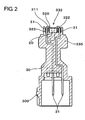
- the connecter housing 30 shown best in Figure 2 is constituted as a formed resin made from PPS (Poly Phenylene Sulfide) resin.
- PPS Poly Phenylene Sulfide
- three terminal pins 31 are embedded in the connecter housing 30 by insert molding.
- end portions of the terminal pins 31 are protruded around the pressure sensing element 20.
- Other end portions of the terminal pins 31 are protruded inside of a socket portion 300 of the connecter housing 30 taking an annular shape.
- the end surface 332 formed on an end in the insertion direction of the connecter housing 30 is provided with a receiving recess or pocket portion 320 for placing the pressure sensing element 20 therein.
- Three pin holes 322 which respectively receive the terminal pins 31 extending toward the end surface 332 are formed around the receiving pocket portion 320 on the end surface 332.
- the pressure sensing element 20 placed in the receiving pocket portion 320 is electrically connected to the terminal pins 31 received in the pin holes 322, through bonding wires 311.
- the terminal pins 31 are composed of three pins for power supplying, ground, and signal outputting.
- a seal layer 323 is formed by filling a seal agent or substance.
- sealing property between the circumferential surface of each terminal pin 31 and the internal surface of an associated pin hole 322 is ensured reliably by the provision of the seal layer 323.
- the pressure sensing element 20 in the present embodiment is of the type that a measuring circuit 22 including a sensor diaphragm and strain gauges (e.g., semiconductor strain gauges) and a compensation circuit 21 including a signal processing section 213 for performing the processing and operation of the measured signal of the measuring circuit 22 are integrally formed on a silicon substrate.
- a measuring circuit 22 including a sensor diaphragm and strain gauges (e.g., semiconductor strain gauges) and a compensation circuit 21 including a signal processing section 213 for performing the processing and operation of the measured signal of the measuring circuit 22 are integrally formed on a silicon substrate.
- the measuring circuit 22 is constituted to measure the magnitude of the pressure acting on the sensor diaphragm by measuring the stress exerted on the sensor diaphragm with the strain gauges.
- the compensation circuit 21 is constituted to externally output a measured signal from the measuring circuit 22 after the processing of the measured signal.
- the measuring circuit 22 is not limited to that of the aforementioned construction. Instead, the measuring circuit 22 may be constructed by utilizing a pressure-resistance effect element which varies electric resistance in dependence on the pressure applied thereto, an electrostatic capacity element which detects as a variation of electrostatic capacity the transformation or displacement of a diaphragm having a pressure applied thereon, or the like.
- the compensation circuit 21 is composed of the aforementioned data communication interface section 211 having a loop antenna 211 a and operable for receiving the compensation data through the loop antenna 211 a, the aforementioned memory section 212 for storing the received compensation data therein, the aforementioned compensation data writing section 214 for writing the compensation data in the memory section 212, and the aforementioned signal processing section 213 for performing the processing and operation of the aforementioned measured signal based on the compensation data stored in the memory section 212.
- the pressure sensing element 20 is constructed to be operated by the voltage applied between a power supply terminal 201 and a ground terminal 202.
- the signal processing section 213 in the present embodiment is provided with a register section (not shown) for reading the compensation data stored in the memory section 212 and a D-A converter section (not shown) with ladder-type resistances, at a portion operating as an interface with the memory section 212.
- the signal processing section 213 generates an analogue voltage corresponding to digital data read into the register section by properly switching the ladder-type resistances, constituting the D-A converter section, based on the digital data.
- the signal processing section 213 takes the analogue voltage as reference voltage and performs analogue-type signal processing on the measured signal.
- the signal processing section 213 may be constituted by utilizing a microcomputer of a miniature scale, in which case the pressure sensing element 20 is constituted to include such a microcomputer.
- the signal processing method can be altered by rewriting the software programs incorporated in the microcomputer.
- This adjusting process is the process which is implemented by using an adjusting device (not shown) as manufacturing installations.
- the adjusting device includes a constant temperature reservoir (not shown) having a pressure tank adjustable desirably in pressure and capable of desirably adjusting the temperature of the interior thereof in which the pressure tank is arranged, and a data transfer PC (Personal Computer, not shown) for calculating the compensation data and for radio-transmitting the compensation data.
- the adjusting device is constructed by connecting the constant temperature reservoir to the data transfer PC by means of a communication cable such as RS232C or the like.
- the pressure tank is constructed so that the pressure sensor 11 is able to be joined with the pressure tank by being screw-engaged therewith at the male screw portion 422 thereof. Further, within the interior of the constant temperature reservoir, an external connecter is arranged to be connectable with the socket portion 300 of the pressure sensor 11. Thus, through the external connecter, the adjusting device is able to operate the pressure sensor 11 contained in the constant temperature reservoir and to take the output signal from the pressure sensor 11.
- the data transfer PC is able to take the output signal from the pressure sensor 11 together with data about the pressure and temperature acting on the pressure sensor 11. Then, the data transfer PC is able to calculate a zero-point compensation value, a compensation gain value and the like to be set into the compensation circuit 21, based on the measured data taken thereinto.
- the data transfer PC is provided with an external connecter which is connectable with the pressure sensor 11 after the same is taken out of the constant temperature reservoir.
- the data transfer PC is able to radio-transmit the compensation data to the pressure sensor 11 connected to the external connecter thereof.
- the adjusting process is the process which is implemented for an assembled pressure sensor 11 after an assembling step of the pressure sensor 11.
- the assembled pressure sensor 11 is provided.
- the aforementioned constant temperature reservoir is used, in which the pressure sensor 11 is joined with the aforementioned pressure tank and is also connected to the external connecter at the socket portion 300 thereof.
- the constant temperature reservoir is operated in accordance with a programmed procedure.
- the constant temperature reservoir alters the tank pressure and the reservoir interior temperature successively and takes the output signal of the pressure sensor 11 at the time of each such alteration to output the output signal to the data transfer PC.
- the constant temperature reservoir may be constructed to be operated in accordance with control signals input from the data transfer PC or may be constructed to be operated in accordance with commands and the like given by the microcomputer incorporated in the constant temperature reservoir.
- the pressure sensor 11 is taken out of the constant temperature reservoir. Then, the external connecter of the data transfer PC is connected to the pressure sensor 11. Then, a compensation data calculation program and a data communication program stored in the data transfer PC are executed in turn. In accordance with the compensation data calculation program, the compensation data is calculated based on the measured data which was taken from the pressure sensor 11 in the constant temperature reservoir. In accordance with the data communication program, the calculated compensation data is transmitted to the pressure sensor 11.
- the data transfer PC may be programmed to transmit the compensation data to the constant temperature reservoir.
- the compensation data can be set in the pressure sensor 11 which is contained in the constant temperature reservoir in connection to the connecter of the same.
- the pressure sensor 11 receives the radio-transmitted compensation data from the data communication interface section 211.
- the received compensation data is transmitted to the compensation data writing section 214 and further, is written into the memory section 212.
- the compensation data can be stored in the memory section 212 of the pressure sensor 11 by making the data transfer PC execute the data communication program. After having stored the appropriate compensation data in the memory section 212, the pressure sensor 11 is enabled to measure the pressure as precise as specified in the design specification and hence, to produce an output signal enhanced in reliability.
- Pressure sensors 11 which are uniform in quality without differences thereamong and which are enhanced in reliability can be produced where the foregoing adjusting process is implemented on every one of the pressure sensors 11 so produced.
- each of the pressure sensors 11 can have set therein the compensation data which is highly precise as being capable of absorbing the variation in property caused by non-uniformity or the like in assembling operation.
- the pressure sensor 11 in the present embodiment receives the radio-transmitted compensation data and sets the same in the compensation circuit 21. Therefore, it is unnecessary to provide the pressure sensor 11 in the present embodiment with any communication terminal or the like to take the compensation data thereinto, and thus, the cost for providing the communication terminal can be saved in the pressure sensor 11 in the present embodiment.
- the communication terminal is generally the terminal which is needed only in the adjusting process, but is not used at all after the product shipment. For this reason, in the manufacturing process for the prior art pressure sensor, it is sometimes the case that the communication terminal is covered to be isolated with an isolation member after the implementation of the foregoing adjusting process. Accordingly, where the communication terminal is omitted as is the case of the pressure sensor in the present embodiment, it is possible to remarkably improve the productivity thereof by the omission of the process for isolating the communication terminal after the adjusting process.
- a compensation element 24 with the compensation circuit 21 formed thereon may be constructed independently of the pressure sensing element 20.
- the compensation element 24 may be arranged together with the pressure sensing element 20 within the pressure chamber 452 or may be arranged outside of the pressure chamber 452, e.g., within the formed plastic constituting the connecter housing 30.
- a pressure sensor 11 in the present embodiment is built on the pressure sensor 11 in the first embodiment and is further improved in operation reliability.
- the pressure sensor 11 in the second embodiment will be described hereafter with reference to Figure 6.
- the components which perform the same functions as those in the first embodiment are shown to be designated by the same or corresponding reference numerals.
- a fuse section 219 which is fused when the voltage of a predetermined value or greater is applied thereto is arranged on a power supply path 218 extending from a power supply terminal 201 to a compensation data writing section 214.
- a pressure sensing element 20 in the second embodiment including the compensation circuit 21 is the element operable at the voltage of five (5) volts.
- seven (7) volts or greater is set as an upper limit of a permissible voltage range within which any voltage does not damage the circuit when applied to the same.
- the fuse section 219 arranged on the foregoing power supply path 218 is constituted to be melt and cut when the voltage of seven (7) volts or so is applied thereto.
- an adjusting process in the present embodiment for setting the compensation data to the pressure sensor 11 includes a step of executing a data communication program by a data transfer PC.
- the data communication program in the present embodiment is different from the data communication program in the first embodiment in that the voltage of approximately seven (7) volts is applied to the power supply terminal of an external connecter connected to the pressure sensor 11 at the time of the program end.
- the pressure sensing element 20 in the present embodiment it is possible to melt and cut the fuse section 219 after the setting of the compensation data.
- the pressure sensor 11 in the present embodiment it can be realized to highly reliably terminate the power supply to the compensation data writing section 214 after the implementation of the adjusting process. Therefore, the compensation data writing section 214 can be prevented highly reliably from being erroneously operated after the adjusting process.
- the power supply to the compensation data writing section 214 is terminated after the setting of the compensation data. Therefore, it hardly occurs that the compensation data is rewritten through the erroneous operation caused by noise or the like of the compensation data writing section 214 during the use of the pressure sensor 11 in the present embodiment.
- the pressure sensor 11 in the present embodiment becomes highly reliable in that it can precisely carry out the pressure measurement over a long term of use.
- the power supply path 218 may be formed independently of the power supply path for the pressure sensing element 20. In this case, it can be realized to apply a higher voltage to the power supply path 218, so that the fuse section 219 can be melt and cut more reliably.
- the present embodiment is directed to a pressure sensor which is improved in the sealing capability of the pressure chamber, and the pressure sensor in the third embodiment will be described hereafter with reference to Figures 7 to 10.
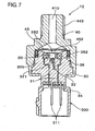
- a pressure sensor 12 in the present embodiment is provided with a pressure sensing element 20 for measuring the magnitude of a pressure acting thereon and a pressure chamber 452 accommodating the pressure sensing element 20.
- the pressure sensor 12 incorporates therein an annular induction coil 36 and a housing side communication interface section 32 which is constructed to receive a measured signal of the pressure sensing element 20 transmitted thereto by means of radio.
- a secondary coil 231 constructed to be magnetically joined with the induction coil 36 and a pressure chamber side communication interface section 232 constructed to radio-transmit the measured signal of the pressure sensing element 20.
- a pressure chamber side communication interface section 232 constructed to radio-transmit the measured signal of the pressure sensing element 20.
- the pressure sensor 12 is constituted by combining a connecter housing 30 having an end surface 332 on which the pressure sensing element 20 is arranged, and a sensor housing 40 constructed to have the connecter housing 30 inserted thereinto.
- the pressure chamber 452 is defined between the end surface 332 of the connecter housing 30 and the sensor housing 40.
- the sensor housing 40 has a seal diaphragm 45 welded to seal the pressure chamber 452 fluid-tightly.
- the pressure sensor 12 transmits the pressure acting on the seal diaphragm 45 to the pressure sensing element 20 through pressure transmission medium filled in the pressure chamber 452.
- the sensor housing 40 is made of stainless steel and takes a generally cylindrical shape having a through hole 410 passing therethrough in the axial direction.
- the sensor housing 40 has an insertion section 335 of the connecter housing 30 inserted thereinto and fixedly secures the insertion section 335 thereto by caulking an open end portion of the sensor housing 40.
- An O-ring 352 for sealing the gap between the connecter housing 30 and the sensor housing 40 is arranged on the internal surface of the sensor housing 40 receiving the insertion section 335 therein.
- a male screw portion 442 is formed on the circumferential surface of a cylindrical portion of the sensor housing 40 defining the through hole 410 therein.
- the pressure sensor 12 is adapted to be connected to a pipe, conduit or the like in which fluid to be measured flows, by being screwed therein at the male screw portion 442.
- the fluid to be measured flows thereinto through the through hole 410 and acts on the seal diaphragm 45.
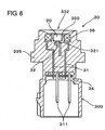
- the connecter housing 30 shown best in Figure 8 in the present embodiment is constituted by a resin-formed member which is formed by PPS resin, a kind of synthetic resin.
- the connecter housing 30 Provided by insert forming inside the connecter housing 30 are the aforementioned annular induction coil 36 arranged to surround the pressure sensing element 20 and the aforementioned housing side communication interface section 32 constructed to receive the measured signal of the pressure sensing element 20 radio-transmitted thereto.
- the connecter housing 30 is provided on the end surface 332 of the insertion portion 335 thereof with a receiving recess or pocket portion 320 for placing the pressure sensing element 20 therein.
- a socket portion 300 which takes an annular shape for connection with an external connecter (not shown) is formed at a side opposite to the insertion portion 335. Terminal pins 311 for power supplying, ground and signal outputting are arranged inside the socket portion 300.
- the connecter housing 30 in the present embodiment there are incorporated by insert forming the annular induction coil 36 arranged to surround the external surface of the receiving pocket portion 320, an antenna section 321 of the housing side communication interface section 32 arranged to face the bottom portion of the receiving pocket portion 320, and terminal pins 31 electrically connected respectively to the induction coil 36 and the antenna section 321.
- the induction coil 36 may be arranged along the bottom portion of the receiving pocket portion 320. Moreover, the induction coil 36 may be arranged at any place which is able to realize the magnetic connection with the secondary coil 231 ( Figure 9).
- end portions at the socket portion 300 of the terminal pins 31 are protruded from the bottom surface of the socket portion 300.
- a control board 34 which includes a power supply circuit for supplying electric power to the induction coil 36 and a communication circuit constituting the housing side communication interface section 32.
- Each of the terminal pins 31 is electrically connected to the control board 34, which is electrically connected in turn to the terminal pins 311 protruding into the socket portion 300.
- the pressure sensing element 20 is the element which is constituted by integrally forming on a silicon substrate a measuring circuit 22 including a sensor diaphragm and strain gauges (e,g., semiconductor strain gauges), a signal processing section 213 for performing the processing such as amplification or the like of the measured signal of the measuring circuit 22, a power supply section 230 for rectifying the inductive voltage generated on the secondary coil 231, and a pressure chamber side communication interface section 232 including an antenna (not shown).
- the secondary coil 231 is arranged to turn around the peripheral portion of the silicon substrage.
- the pressure sensing element 20 is operable by the electric current rectified by the power supply section 230.
- the measuring circuit 22 measures the magnitude of the pressure acting on the sensor diaphragm by measuring the stress exerted on the sensor diaphragm with the strain gauges.
- the pressure chamber side communication interface section 232 radio-transmits the measured signal of the measuring circuit 22 which signal is amplified through the signal processing section 213.
- the measuring circuit 22 is not limited to that of the aforementioned construction. Instead, the measuring circuit 22 may be constructed by utilizing a pressure-resistance effect element which varies electric resistance in dependence on the pressure applied thereto, an electrostatic capacity element which detects as a variation of electrostatic capacity the displacement of a diaphragm having a pressure applied thereon, or the like.
- the pressure sensor 12 can be realized to supply electric power to the pressure sensing element 20 in a non-contact manner through the magnetic connection of the induction coil 36 with the secondary coil 231. Further, it can be realized to receive the measured signal of the measuring circuit 22 which is radio-transmitted through the pressure chamber side communication interface section 232, by the use of the antenna section 321 of the housing side communication interface section 32.
- the sealing of the pressure chamber 452 can be improved, so that the reliability in operation can be improved remarkably.
- the pressure sensor 12 improved in sealing the pressure chamber 452 has a good quality as being capable of maintaining a stable measuring performance over a long term of use.
- a sealing process which is essential to the pressure sensor in the prior art for filling seal substance around each terminal pin can be omitted, so that the productivity can be enhanced remarkably.
- control board 34 is secured at the bottom portion of the socket portion 300.
- an external controller used in combination with the pressure sensor, wherein the control board is arranged in the external controller and wherein the terminal pins 31 are provided to extend in the socket portion 300.
- not only the control board 34 but also the induction coil 36 and the housing side communication interface section 32 as used in the third embodiment may be provided separately from a pressure sensor 13.
- a communication interface section with a multiplex communication channel is utilized in place of the housing side communication interface section 32 in the present embodiment, it can be realized to construct a system which is capable of receiving output signals of plural pressure sensors 13 by the use of one communication interface section.
- it can be realized to receive the output signals of the plural pressure sensors 13 separately and reliably by utilizing time-shared multiplex communication, frequency-shared multiplex communication, or spread-spectrum communication capable of performing multipath communication.
- the pressure sensing element 20 can be realized to supply the pressure sensing element 20 with electric power from the outside of the pressure sensor 13 in a non-contact manner by utilizing the induction coil arranged around the pressure sensor 13. Furthermore, where the operating electric power for the pressure sensing element 20 is transmitted by means of a radio wave, an electric power transmitter replacing the induction coil can be arranged at any desired place.
- a pressure sensor in the present embodiment is built on the pressure sensor in the third embodiment and is further improved to perform the setting of compensation data for compensating the measured signal, in a non-contact manner.
- this embodiment will be described with reference to Figure 11.
- a pressure sensing element 20 in this embodiment is the element which is constituted by integrally forming on a silicon substrate a measuring circuit 22 including a sensor diaphragm and strain gauges (e.g., semiconductor strain gauges), a signal processing section 213 for performing the processing such as amplification or the like of a measured signal of the measuring circuit 22, a power supply section 230 for rectifying the inductive voltage generated on a secondary coil 231, and a pressure chamber side communication interface section 232 including an antenna (not shown) and in addition to these components, by further integrally forming on the silicon substrate a compensation unit section 221 for controlling the operation of the signal processing section 213.
- the secondary coil 231 is arranged to turn around the peripheral portion of the silicon substrate as is the case of the third embodiment.
- the compensation unit section 221 is composed of a memory section 212 for storing the compensation data and a compensation data writing section 214 for writing the compensation data in the memory section 212.
- a compensation circuit 21 for performing the compensation, amplification and the like of the measured signal of the measuring circuit 22 is formed by the compensation unit section 221 and the signal processing section 213.
- the compensation data includes a zero-point compensation value, a compensation gain value and the like which are used to compensate the measured signal of the measuring circuit 22.
- the pressure chamber side communication interface section 232 is used to receive the compensation data transmitted by means of radio.
- a register section 231r for reading the compensation data stored in the memory section 212 and a D-A converter 213c with ladder-type resistances are formed in the signal processing section 213 at a portion which constitutes an interface with the memory section 212.
- the signal processing section 213 generates an analogue voltage corresponding to the digital data by properly switching the ladder-type resistances constituting the D-A converter 213c, based on the digital data read in the register section 213r.
- the signal processing section 213 takes the analogue voltage as reference voltage and performs analogue-type signal processing on the measured signal.
- the pressure sensing element 20 may be constituted to include a microcomputer, so that the signal processing section 213 can be constituted by using the microcomputer:
- the signal processing method for the measured signal may be altered by rewriting software programs incorporated in the microcomputer.
- This adjusting processing is the processing which is implemented by using an adjusting device (not shown) as manufacturing installations.
- the adjusting device includes a constant temperature reservoir (not shown) having a pressure tank adjustable desirably in pressure and capable of desirably adjusting the temperature of the interior thereof in which the pressure tank is arranged, and a data transfer PC (Personal Computer, not shown) for calculating the compensation data and for radio-transmitting the compensation data and is constructed by connecting the constant temperature reservoir to the data transfer PC by means of a communication cable such as RS232C or the like.
- a communication cable such as RS232C or the like.
- the pressure tank is constructed so that the pressure sensor 12 is able to be joined with the pressure tank by being screw-engaged therewith at the male screw portion 442 (shown in Figure 7) thereof. Further, within the interior of the constant temperature reservoir, an external connecter is arranged for connection with the socket portion 300 ( Figure 7) of the pressure sensor 12. Thus, through the external connecter, the adjusting device is able to operate the pressure sensor 12 contained in the constant temperature reservoir and to take the output signal out.
- the data transfer PC is able to take thereinto the output signal of the pressure sensor 12 together with respective data about the pressure and temperature acting on the pressure sensor 12. Then, the data transfer PC calculates compensation data such as a zero-point compensation value, a compensation gain value and the like to be set into the compensation unit section 221, based on the measured data taken thereinto.
- the data transfer PC is provided with an external connecter which is connectable with the pressure sensor 12 after the same is taken out of the constant temperature reservoir.
- the data transfer PC is able to transmit the compensation data to the pressure sensor 12 connected to the external connecter thereof.
- the adjusting process is the process which is implemented for an assembled pressure sensor 12 after an assembling step of the pressure sensor 12.
- the assembled pressure sensor 12 is provided.
- the aforementioned constant temperature reservoir is used, in which the pressure sensor 12 is joined with the aforementioned pressure tank and is also connected to the external connecter at the socket portion 300 thereof.
- the constant temperature reservoir is operated in accordance with a programmed procedure.
- the constant temperature reservoir alters the tank pressure and the reservoir interior temperature successively and takes thereinto the output signal of the pressure sensor 12 at the time of each such alteration to output the output signal to the data transfer PC.
- the pressure sensor 12 is taken out of the constant temperature reservoir. Then, the external connecter of the data transfer PC is connected to the pressure sensor 12. Then, a compensation data calculation program and a data communication program stored in the data transfer PC are executed in turn. In accordance with the compensation data calculation program, the compensation data is calculated based on the measured data taken from the constant temperature reservoir. Also in accordance with the data communication program, the calculated compensation data is transmitted to the pressure sensor 12.
- the data transfer PC may be programmed to transmit the compensation data to the constant temperature reservoir.
- the compensation data can be set in the pressure sensor 12 which is contained in the constant temperature reservoir in connection to the connecter of the same.
- the pressure sensor 12 receives the compensation data radio-transmitted by the pressure chamber side communication interface section 232.
- the received compensation data is transmitted to the compensation data writing section 214 of the compensation unit section 221 and further, is written into the memory section 212.
- the compensation data can be stored in the memory section 212 of the compensation unit section 221 when the data transfer PC executes the data communication program in this way. After having stored the appropriate compensation data in the memory section 212, the pressure sensor 12 is enabled to measure the pressure as precise as specified in the design specification and hence, to produce an output signal enhanced in reliability.
- Pressure sensors 12 which are uniform in quality without differences thereamong and which are enhanced in reliability can be manufactured where the foregoing adjusting process is implemented on every one of the pressure sensors 12 so manufactured.
- each of the pressure sensors 12 can have set therein the compensation data which is highly precise as being capable of absorbing the variation in property caused by the non-uniformity or the like in assembling operation.
- the communication terminal is generally the terminal which is needed only in the adjusting process, but is not used at all after the product shipment. For this reason, in the manufacturing process for the prior art pressure sensor, it is sometimes the case that the communication terminal is covered to be isolated with an isolation member after the implementation of the foregoing adjusting process. Accordingly, where the communication terminal is omitted as is the case of the pressure sensor 12 in the present embodiment, it is possible to remarkably improve the productivity thereof by the omission of the process for isolating the communication terminal after the adjusting process.
- a pressure sensor in the present embodiment is built on the pressure sensing element 20 in the fourth embodiment and is further improved to provide a secondary coil as a separate component.
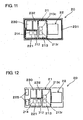
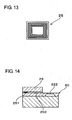
- this embodiment will be described with reference to Figures 12 through 14.
- a secondary coil as indicated at 231 in Figure 11 is omitted, in place of which two joint pads 225 are formed for realizing the electric connection with a coil element 25 referred to later.
- the coil element 25 is the element in which a plurality of conductive lead patterns are arranged on a silicon substrate with one surrounding another, as shown in Figure 13.
- the coil element 25 is provided with two terminal pad portions (not shown) which are electrically connected to both ends of the coil patterns, at positions corresponding to the two joint pad portions 225 ( Figure 12) of the pressure sensing element 20.
- the joint pad portions 225 are faced with the terminal pad portions.
- the joint pad portions 225 and the terminal pad portions are bonded with a conductive member 251 arranged therebetween and with isolation bonding agent 252 applied between the coil element 25 and the pressure sensing element 20.
- the coil element 25 in the present embodiment is constructed to have its element surface of the dimension which is left by excluding the area for a measuring circuit 22 including a sensor diaphragm 222 from the element area for the pressure sensing element 20.
- the sensor diaphragm 222 remains naked, while a signal processing section 213, a pressure chamber side communication interface section 232, a power supply section 230 and a compensation unit section 221 are protected by being covered up. Therefore, the pressure sensor 12 in the present embodiment is improved in the endurance of the pressure sensing element 20 and is able to maintain a good measuring performance for a long period of time.
- Other constructions, functions and advantages of the pressure sensor 12 in the present embodiment are the same as those in the fourth embodiment.
- the pressure sensor 11 is provided with the compensation circuit 21 which includes the data communication interface section 211, the memory section 212, and the compensation data writing section 214.
- the compensation circuit 21 is able to receive the compensation data which is transmitted by means of radio from a transmission antenna provided externally, in a non-contact manner by the use of the data communication interface section 211 and is also able to store the received compensation data in the memory section 212 by the use of the compensation data writing section 214.
- the signal processing section 213 precisely performs the processing and operation of the measured signal of the pressure sensing element 20 based on the compensation data stored in the memory section 212.
- the compensation data can be stored in the memory section 212 quite easily, e.g., even after the assembling.
- the pressure sensor 11 can suppress the non-uniformity in measured signal among the pressure sensors 11 which non-uniformity is caused by the fluctuation in the assembling condition of the pressure sensors 11, and can become enhanced in measuring accuracy.
- the compensation data is input in a non-contact manner to be set in the compensation circuit 21, the pressure sensor 11 does not need to be provided with any communication terminal or the like for taking the compensation data thereinto.
- the pressure sensing element 20 is integrally provided with the compensation circuit 21.
- the pressure sensing element 20 and the compensation circuit 21 can be properly integrated and constructed to be compact.
- both of them may be arranged in the pressure chamber 452, or the compensation circuit 21 only may be arranged outside the pressure chamber 452.
- the fuse section 219 which is melt and cut when given electric power equal to or greater than a predetermined value is arranged on the electric power supply path 218 for supplying the compensation data writing section 214 with operating electric power.
- the compensation data writing section 214 can be reliably prevented from being operated erroneously.
- the fuse section 219 is melt and cut after the storing of the compensation data in the memory section 212, it can be suppressed that the compensation data is written carelessly by the erroneous operation of the compensation data writing section 214.
- the compensation data writing section 214 is electrically connected to the power supply terminal 201 of the compensation circuit 21 through the electric power supply path 218, and the fuse section 219 is constructed to be melt and cut by having applied thereto a voltage which is equal to or greater in value than an appropriate voltage to be applied to the power supply terminal 201 of the compensation circuit 21 and which is within a permissible range of the voltage permissible to be applied to the compensation circuit 21. In this case, it is unnecessary to provide the electric power supply path 218 independently of an electric power supply path for the compensation circuit 21.
- the electric power supply path 218 can be commonly used also as the power supply path for the compensation circuit 21.
- the compensation circuit 21 is of the type that is driven by the voltage of five (5) volts
- the fuse section 219 is constituted to be melt and cut when having applied thereto the voltage of seven (7) volts or so. The reason for this is because it is general that the compensation circuit 21 which is operated by the drive voltage of five (5) volts is hardly damaged by having the voltage of seven (7) volts or so applied thereto.
- the pressure sensor 11 is constituted by combining the connecter housing 30 holding the pressure sensing element 20, with the sensor housing 40 constituted to have the connecter housing 30 inserted thereinto and has the pressure chamber 452 defined between the connecter housing 30 and the sensor housing 40, and the pressure sensing element 20 is arranged in the pressure chamber 452.
- the pressure chamber 452 is fluid-tightly sealed with the seal diaphragm 45 and has pressure transmission medium filled therein.
- the pressure sensing element 20 can be sealed with the seal diaphragm 45, so that the foregoing advantages can become more effective.
- the induction coil 36 and the housing side communication interface section 32 are provided independently of the pressure chamber 452, and the secondary coil 231 and the pressure chamber side communication interface section 232 are arranged in the pressure chamber 452.
- the positional relation in which the induction coil 36 or the housing side communication interface section 32 is independent of the pressure chamber 452 means the following positional relation. That is, it is meant by the positional relation that neither the induction coil 36 nor the housing side communication interface section 32 is arranged in the pressure chamber 452 and that the external surfaces of the induction coil 36 and the housing side communication interface section 32 are not naked or exposed to the pressure chamber 452 at all.
- the induction coil 36 By combining the induction coil 36 with the secondary coil 231, it can be realized to supply required operating electric power in a non-contact manner to the pressure sensing element 20 in the pressure chamber 452 from the outside of the pressure chamber 452.
- the housing side communication interface section 32 By combining the housing side communication interface section 32 with the pressure chamber side communication interface section 232, it can be realized to transmit the measured signal of the pressure sensing element 20 toward the outside of the pressure chamber 452 by means of radio. Then, the pressure sensor 12 can output toward an external device or the like the measured signal received by the housing side communication interface section 32.
- the pressure sensor 12 does not need to be provided with any terminal pin for supplying the operating electric power to the pressure sensing element 20 in the pressure chamber 452 and any other terminal pin for transmitting the measured signal of the pressure sensing element 20 from within the pressure chamber 452 toward the outside of the same, in such a manner as to protrude any such terminal pin into the pressure chamber 452.
- the pressure sensor 12 it is not needed to seal the circumference of each of such terminal pins with sealing agent. Therefore, the pressure sensor 12 can become remarkably easier in maintaining the sealing of the pressure chamber 452. This enables the pressure sensor 12 to maintain the sealing of the pressure chamber 452 and a good measuring performance over a long term of use. That is, the pressure sensor 12 in the third embodiment can be manufactured in a high productivity, can be of low cost and can have a good quality as being capable of maintaining good performance over a long period of time.
- the compensation unit section 221 is arranged in the pressure chamber 452 and includes the memory section 212 for storing the compensation data and the compensation data writing section 214 for writing the compensation data in the memory section 212.
- the signal processing section 213 is also arranged in the pressure chamber 452 for performing the processing and operation of the measured signal based on the compensation data stored in the memory section 212.
- the pressure chamber side communication interface section 232 is provided for receiving the compensation data radio-transmitted thereto and for writing the compensation data in the compensation data writing section 214.
- the compensation data which is radio-transmitted from the housing side communication interface section 32 or a transmission device or the like which is provided independently of the pressure sensor 12 is received by the use of the pressure chamber side communication interface section 232, and subsequently, the compensation data can be set in the compensation circuit 21 at any time as desired.
- the signal processing section 213 performs the processing and operation of the measured signal based on the compensation data stored in the memory section 212. Therefore, it is unnecessary to arrange any terminal pin or the like for setting the compensation data in the compensation circuit 21 in such a manner as to protrude any such terminal pin into the pressure chamber 452. As a consequence, it becomes easier to maintain the pressure chamber 452 sealed satisfactorily, so that the pressure sensor 12 with the pressure chamber 452 so constructed can be remarkably enhanced in operational reliability.
- the pressure sensor 12 is constituted by combining the connecter housing 30 holding the pressure sensing element 20, with the sensor housing 40 constituted to have the connecter housing 30 inserted thereinto and has the pressure chamber 452 defined between the connecter housing 30 and the sensor housing 40, and the connecter housing 30 is made by forming synthetic resin to incorporate the induction coil 36 and the housing side communication interface section 32 therein by insert forming.
- the connecter housing 30 by combining the connecter housing 30 with the sensor housing 40, it can be realized to effectively define the pressure chamber 452 therebetween. Further, since the induction coil 36 and the housing side communication interface section 32 are assembled by insert forming, it can be realized to form in a high productivity the connecter housing 30 incorporating the induction coil 36 and the housing side communication interface section 32.
- a recess portion or the like for accommodating the induction coil 36 or the housing side communication interface section 32 may be defined independently of the pressure chamber 452 when the connecter housing 30 is formed. In this case, it becomes possible to assemble the induction coil 36 or the housing side communication interface section 32 in the connecter housing 30 after the forming of the same.
Landscapes
- Physics & Mathematics (AREA)
- General Physics & Mathematics (AREA)
- Chemical & Material Sciences (AREA)
- Analytical Chemistry (AREA)
- Measuring Fluid Pressure (AREA)
Applications Claiming Priority (2)
| Application Number | Priority Date | Filing Date | Title |
|---|---|---|---|
| JP2003427748A JP2005188980A (ja) | 2003-12-24 | 2003-12-24 | 圧力センサ |
| JP2003427748 | 2003-12-24 |
Publications (2)
| Publication Number | Publication Date |
|---|---|
| EP1550852A2 true EP1550852A2 (de) | 2005-07-06 |
| EP1550852A3 EP1550852A3 (de) | 2005-08-03 |
Family
ID=34567553
Family Applications (1)
| Application Number | Title | Priority Date | Filing Date |
|---|---|---|---|
| EP04029838A Withdrawn EP1550852A3 (de) | 2003-12-24 | 2004-12-16 | Druckaufnehmer mit System zur drahtlosen Signalübertragung |
Country Status (5)
| Country | Link |
|---|---|
| US (1) | US7194375B2 (de) |
| EP (1) | EP1550852A3 (de) |
| JP (1) | JP2005188980A (de) |
| KR (1) | KR20050065329A (de) |
| CN (1) | CN100439889C (de) |
Cited By (2)
| Publication number | Priority date | Publication date | Assignee | Title |
|---|---|---|---|---|
| US7934426B2 (en) | 2007-03-26 | 2011-05-03 | Vega Grieshaber Kg | Measurement cell system, in particular pressure measurement cell system |
| GB2582772A (en) * | 2019-04-02 | 2020-10-07 | Aspen Pumps Ltd | Adapter for a manifold gauge assembly, a manifold gauge assembly, and a method of adapting a manifold gauge assembly |
Families Citing this family (18)
| Publication number | Priority date | Publication date | Assignee | Title |
|---|---|---|---|---|
| JP4646750B2 (ja) * | 2005-09-08 | 2011-03-09 | 三洋電機株式会社 | 空気調和装置、室外ユニットの制御方法、および、室外ユニットの制御プログラム |
| JP2007078397A (ja) * | 2005-09-12 | 2007-03-29 | Mitsubishi Electric Corp | 半導体圧力センサ |
| KR100892387B1 (ko) | 2006-05-15 | 2009-04-16 | 김영민 | 생물체 내부 검진용 캡슐형 알에프아이디 센서 태그 |
| CN101553719B (zh) * | 2006-11-22 | 2011-07-06 | 丹福斯有限公司 | 压力传感器 |
| KR100941665B1 (ko) * | 2007-10-23 | 2010-02-11 | 주식회사 피디케이 | 초정밀 압력측정장치 |
| DE102008043517B4 (de) * | 2008-11-06 | 2022-03-03 | Robert Bosch Gmbh | Sensormodul und Verfahren zur Herstellung eines Sensormoduls |
| CN102042897A (zh) * | 2009-10-12 | 2011-05-04 | 西安威尔罗根能源科技有限公司 | 一种压力传感器的压力校验装置 |
| JP2013040914A (ja) * | 2011-08-15 | 2013-02-28 | Toyo Denshi Kenkyusho:Kk | 校正機能付き冷陰極形電離真空計 |
| US9217684B2 (en) * | 2012-11-30 | 2015-12-22 | B/E Aerospace, Inc. | Oxygen system having sensors with a passive RFD interface |
| TWI633289B (zh) * | 2013-03-13 | 2018-08-21 | 不二工機股份有限公司 | 壓力感測器 |
| JP2015121485A (ja) * | 2013-12-24 | 2015-07-02 | 株式会社不二工機 | 圧力センサ |
| WO2016061375A1 (en) * | 2014-10-16 | 2016-04-21 | Trensor, LLC | Climate control pressure plug with sensor |
| CN105509955A (zh) * | 2015-12-21 | 2016-04-20 | 上海自动化仪表有限公司 | 基于cmc处理器的压力变送器 |
| US12152954B2 (en) * | 2018-06-08 | 2024-11-26 | Orbis Intelligent Systems, Inc. | Detection device for a fluid conduit or fluid dispensing device |
| US12590824B2 (en) | 2018-06-08 | 2026-03-31 | Orbis Intelligent Systems, Inc. | Monitoring sites of a fluid delivery infrastructure |
| CN110398306B (zh) * | 2019-07-08 | 2024-05-07 | 华电电力科学研究院有限公司 | 一种火力发电厂管道应力解耦分析系统与分析方法 |
| CN114486067B (zh) * | 2020-10-26 | 2024-07-30 | 上海华依科技集团股份有限公司 | 一种安装角度360度变化的传感器自动对接测试机构 |
| CN114646420B (zh) * | 2022-05-19 | 2022-07-29 | 成都倍芯传感技术有限公司 | 一种高可靠性的压力变送器 |
Family Cites Families (8)
| Publication number | Priority date | Publication date | Assignee | Title |
|---|---|---|---|---|
| DE4033053C1 (de) * | 1990-10-18 | 1992-03-05 | Hottinger Baldwin Messtechnik Gmbh, 6100 Darmstadt, De | |
| WO1993010498A1 (en) * | 1991-11-12 | 1993-05-27 | Microchip Technology Inc. | Security for on-chip microcontroller memory |
| JP2797880B2 (ja) * | 1993-02-10 | 1998-09-17 | 株式会社日立製作所 | プロセス状態検出装置 |
| FR2727764B1 (fr) * | 1994-12-05 | 1997-01-10 | Alcatel Espace | Restitution de pointage en elevation, notamment pour radar a synthese d'ouverture |
| US5528520A (en) | 1994-12-08 | 1996-06-18 | Ford Motor Company | Calibration circuit for capacitive sensors |
| US6529127B2 (en) * | 1997-07-11 | 2003-03-04 | Microstrain, Inc. | System for remote powering and communication with a network of addressable, multichannel sensing modules |
| JP3620414B2 (ja) | 2000-06-29 | 2005-02-16 | 豊田工機株式会社 | 圧力センサにおける圧力伝達媒体封入方法 |
| JP2003121284A (ja) | 2001-10-09 | 2003-04-23 | Toyoda Mach Works Ltd | 半導体圧力検出装置 |
-
2003
- 2003-12-24 JP JP2003427748A patent/JP2005188980A/ja active Pending
-
2004
- 2004-12-15 US US11/011,065 patent/US7194375B2/en not_active Expired - Fee Related
- 2004-12-16 EP EP04029838A patent/EP1550852A3/de not_active Withdrawn
- 2004-12-17 CN CNB2004101019571A patent/CN100439889C/zh not_active Expired - Fee Related
- 2004-12-17 KR KR1020040108223A patent/KR20050065329A/ko not_active Withdrawn
Cited By (4)
| Publication number | Priority date | Publication date | Assignee | Title |
|---|---|---|---|---|
| US7934426B2 (en) | 2007-03-26 | 2011-05-03 | Vega Grieshaber Kg | Measurement cell system, in particular pressure measurement cell system |
| GB2582772A (en) * | 2019-04-02 | 2020-10-07 | Aspen Pumps Ltd | Adapter for a manifold gauge assembly, a manifold gauge assembly, and a method of adapting a manifold gauge assembly |
| GB2582772B (en) * | 2019-04-02 | 2021-11-17 | Aspen Pumps Ltd | Adapter for a manifold gauge assembly, a manifold gauge assembly, and a method of adapting a manifold gauge assembly |
| US12111222B2 (en) | 2019-04-02 | 2024-10-08 | Aspen Pumps Limited | Manifold assembly digital pressure gauge adapter |
Also Published As
| Publication number | Publication date |
|---|---|
| US7194375B2 (en) | 2007-03-20 |
| CN100439889C (zh) | 2008-12-03 |
| EP1550852A3 (de) | 2005-08-03 |
| US20050139011A1 (en) | 2005-06-30 |
| KR20050065329A (ko) | 2005-06-29 |
| CN1637400A (zh) | 2005-07-13 |
| JP2005188980A (ja) | 2005-07-14 |
Similar Documents
| Publication | Publication Date | Title |
|---|---|---|
| US7194375B2 (en) | Pressure sensor | |
| US7726197B2 (en) | Force sensor package and method of forming same | |
| US7162927B1 (en) | Design of a wet/wet amplified differential pressure sensor based on silicon piezoresistive technology | |
| KR101519395B1 (ko) | 압력 측정 셀용 연결 유닛 | |
| EP3187848B1 (de) | Drucksensoranordnung | |
| CN107941382B (zh) | 用于可靠介质密封的凝胶填充的端口压力传感器 | |
| KR20060086329A (ko) | 밀폐형 압력 감지 장치 | |
| US20070290679A1 (en) | Rotation detection device | |
| US6153070A (en) | Sensor packaging using heat staking technique | |
| JP6461741B2 (ja) | センサパッケージ | |
| JPH07209115A (ja) | 半導体圧力検出器及びその製造方法 | |
| CN113165454A (zh) | 功能部件 | |
| CN1806162B (zh) | 防潮压力传感器 | |
| CN103033231A (zh) | 传感器组件的压力传感器和压力端口之间的接头 | |
| WO2009087767A1 (ja) | 圧力センサ及びその製造方法 | |
| KR101297141B1 (ko) | 압력 센서 및 압력 센서의 부착 구조 | |
| JP2004012406A (ja) | 圧力センサ | |
| CN214309248U (zh) | 传感器 | |
| US10309850B2 (en) | Sealed transducer with external adjustment port | |
| US7168326B2 (en) | Compact pressure sensor with high corrosion resistance and high accuracy | |
| CN115144124B (zh) | 传感器和阀组件 | |
| JP6584618B2 (ja) | センサパッケージ | |
| JPH04370727A (ja) | 半導体圧力センサの製造方法 | |
| CN113108832B (zh) | 传感器 | |
| JP3578347B2 (ja) | 圧力センサ及びその製造方法 |
Legal Events
| Date | Code | Title | Description |
|---|---|---|---|
| PUAI | Public reference made under article 153(3) epc to a published international application that has entered the european phase |
Free format text: ORIGINAL CODE: 0009012 |
|
| PUAL | Search report despatched |
Free format text: ORIGINAL CODE: 0009013 |
|
| AK | Designated contracting states |
Kind code of ref document: A2 Designated state(s): AT BE BG CH CY CZ DE DK EE ES FI FR GB GR HU IE IS IT LI LT LU MC NL PL PT RO SE SI SK TR |
|
| AX | Request for extension of the european patent |
Extension state: AL BA HR LV MK YU |
|
| AK | Designated contracting states |
Kind code of ref document: A3 Designated state(s): AT BE BG CH CY CZ DE DK EE ES FI FR GB GR HU IE IS IT LI LT LU MC NL PL PT RO SE SI SK TR |
|
| AX | Request for extension of the european patent |
Extension state: AL BA HR LV MK YU |
|
| 17P | Request for examination filed |
Effective date: 20060109 |
|
| AKX | Designation fees paid |
Designated state(s): DE |
|
| RAP1 | Party data changed (applicant data changed or rights of an application transferred) |
Owner name: JTEKT CORPORATION |
|
| RIN1 | Information on inventor provided before grant (corrected) |
Inventor name: YAMAKAWA, TOMONARI |
|
| 17Q | First examination report despatched |
Effective date: 20061031 |
|
| STAA | Information on the status of an ep patent application or granted ep patent |
Free format text: STATUS: THE APPLICATION IS DEEMED TO BE WITHDRAWN |
|
| 18D | Application deemed to be withdrawn |
Effective date: 20100202 |