EP1552937B1 - Druckpumpensystem - Google Patents
Druckpumpensystem Download PDFInfo
- Publication number
- EP1552937B1 EP1552937B1 EP05000085A EP05000085A EP1552937B1 EP 1552937 B1 EP1552937 B1 EP 1552937B1 EP 05000085 A EP05000085 A EP 05000085A EP 05000085 A EP05000085 A EP 05000085A EP 1552937 B1 EP1552937 B1 EP 1552937B1
- Authority
- EP
- European Patent Office
- Prior art keywords
- pressure
- opening
- print head
- passage
- pump
- Prior art date
- Legal status (The legal status is an assumption and is not a legal conclusion. Google has not performed a legal analysis and makes no representation as to the accuracy of the status listed.)
- Ceased
Links
- 238000010926 purge Methods 0.000 claims description 28
- 239000012530 fluid Substances 0.000 claims description 10
- 238000000034 method Methods 0.000 claims description 7
- 230000000740 bleeding effect Effects 0.000 claims description 4
- 238000005086 pumping Methods 0.000 claims 1
- 239000002245 particle Substances 0.000 description 4
- 239000007788 liquid Substances 0.000 description 3
- 239000007787 solid Substances 0.000 description 3
- XLYOFNOQVPJJNP-UHFFFAOYSA-N water Substances O XLYOFNOQVPJJNP-UHFFFAOYSA-N 0.000 description 2
- 230000001419 dependent effect Effects 0.000 description 1
- 230000009977 dual effect Effects 0.000 description 1
Images



Classifications
-
- B—PERFORMING OPERATIONS; TRANSPORTING
- B41—PRINTING; LINING MACHINES; TYPEWRITERS; STAMPS
- B41J—TYPEWRITERS; SELECTIVE PRINTING MECHANISMS, i.e. MECHANISMS PRINTING OTHERWISE THAN FROM A FORME; CORRECTION OF TYPOGRAPHICAL ERRORS
- B41J2/00—Typewriters or selective printing mechanisms characterised by the printing or marking process for which they are designed
- B41J2/005—Typewriters or selective printing mechanisms characterised by the printing or marking process for which they are designed characterised by bringing liquid or particles selectively into contact with a printing material
- B41J2/01—Ink jet
- B41J2/17—Ink jet characterised by ink handling
- B41J2/175—Ink supply systems ; Circuit parts therefor
- B41J2/17596—Ink pumps, ink valves
Definitions
- Ink jet printers create an image on a surface by ejecting ink through orifices in a print head face plate, which communicates with a print head.
- the ejected ink droplets are very small, as are the orifices. Since the orifices are very small, an orifice can be partially or completely blocked by an air pocket or a small particle.
- Solid ink printers melt solid ink and deliver the melted ink to the print head.
- the melted ink travels through channels and chambers in the print head towards the reservoirs.
- the solid ink printer is turned off, the ink that remains in the print head can freeze.
- the ink thaws in the print head air that was once in solution in the ink can come out of solution to form air bubbles or air pockets in the print head.
- An obstructed orifice can result in unacceptable printing.
- the obstruction be it an air pocket or a small particle, can usually be removed by purging the orifices.
- a vacuum attaches to the face plate, also known as a jet stack, of the print head and the obstruction is removed by imparting a negative pressure on the face plate.
- the vacuum system is complicated requiring many different parts. Accordingly, it is desirable to purge the orifices, as well as other channels and chambers in the print head, by introducing a positive pressure into the ink channels of the print head to eject obstructions out of the orifices and the ink channels leading to the orifices.
- EP 0 933 216 A2 describes apparatus for restoring ink jet recording head.
- an apparatus for restoring an ink jet recording head which can securely recover the ink jet recording head from the ink non-ejection condition caused by foreign particles or bubbles adhering inside the ink passage of an ejecting nozzle and which can prevent unnecessary bubbles from generating in the ink jet recording head.
- an inner pressure of an ink supply passage is adjusted to reach a set pressure value.
- FIGURE 1 is a schematic of a pump system that can deliver at least two distinct pressures.
- FIGURE 2 is a graph of pressure versus time, in a dual pressure scale, for the pump system of FIGURE 1 .
- FIGURE 3 is a perspective view of an alternative to the pump system of FIGURE 1 .
- FIGURE 4 is a perspective view of a portion of a print head of an ink jet printer and a tube that connects the print head to the pump system of FIGURE 3 .
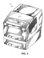
- FIGURE 5 is a perspective view of an ink jet printer that can contain the pump system of FIGURE 1 .
- FIGURE 6 is a side cross-sectional view of the ink jet printer of FIGURE 5 .
- a print head D for an ink jet printer A ( FIGURE 5 ) generally delivers liquid ink to a jet stack B ( FIGURE 6 ) that transfers the ink onto a drum C ( FIGURE 6 ).
- the print media which can include paper, travels around the drum and picks up the ink deposited on the drum.
- a pump 10 communicates with a print head 12 of an ink jet printer (not shown).
- the pump 10 in the exemplary embodiment is a rotary diaphragm air pump; however, other pumps can be used.
- the print head 12 includes a plurality of channels and cavities that direct liquid ink to orifices. Through these orifices, the liquid ink is ejected onto a drum where a print media, i.e. paper, rolls over the drum and picks up the ink forming an image on the print media.
- the print head is more particularly described in pending United States patent applications filed on the same date herewith, assigned to the same assignee as this application and entitled, "Print Head Reservoir Having Purge Vents," “Purgeable Print Head Reservoir,” and “Valve for Printing Apparatus”.
- the orifices, channels and cavities of the print head 12 are purged periodically.
- air under pressure is introduced into the channels and cavities of the print head 12.
- Purge pressures are typically a few to several psi.
- a low pressure assist pressure is usually delivered to the print head, which in an exemplary embodiment is about 0.04 psi.
- the pump 10 delivers air under pressure to the print head 12 at both the purge pressure and the asist pressure.
- the pump 10 communicates with the print head 12 through a passage 14.
- the passage in the exemplary embodiment is plastic tubing.
- the passage 14 includes two openings to control the pressure being delivered to the print head 12.
- the pump 10 runs at a predetermined rate that delivers a known pressure through the passage 14 since the diameter, length and other characteristics of the passage are known.
- the pump in the exemplary embodiment runs at a rate that delivers a pressure through the passage 14 that is higher than the desired purge pressure of the print head. Accordingly, a first opening 16 is provided to bleed off a portion of the fluid, which in the exemplary embodiment is air, flowing through the passage, which results in a lower pressure being delivered to the print head.
- the size of the first opening 16 is determined using methods that are known in the art so that a desired purge pressure can be delivered to the print head 12 when the pump is running at a known rate.
- a commercially available pump that can only deliver a constant pressure that is higher than the desired purge pressure can be used to deliver the purge pressure.
- the system minimizes noise, pressure spikes, etc., to deliver a more constant output pressure to the print head.
- a second opening 18 is located downstream from the first opening 16.
- the second opening 18 allows fluid and/or pressure that was not bled off by the first opening 16 to bleed out of the second opening before traveling to the print head 12, thus the system can deliver a second lower predetermined assist pressure to the print head.
- the size of the second opening 18 is determined using methods that are known in the art so that a desired assist pressure can be delivered to the print head 12 when the pump is running at a known rate.
- the second opening 18 communicates with a valve 22 that selectively opens and closes the second opening 18.
- the valve in the exemplary embodiment is a solenoid valve; however, other conventional valves can also be used.
- the valve 22 communicates with a processor 24 that controls the valve.
- line 30 depicts the pressure rise during a purge cycle from time 0 to approximately 2.7 seconds.
- the processor 24 delivers a signal to the valve 22 to close the opening 18.
- the pressure being delivered to the print head 12 during a purge cycle rises up to about 4.1 psi at 2.7 seconds.
- the processor 24, which includes a timer opens the valve 22 at a predetermined time (2.7 seconds in this example), and air bleeds off through the passage 18 quickly lowering the pressure delivered to the print head to about 1.3 inches of water, as seen from line 32.
- Lines 30 and 32 represent the same purge cycle, but line 30 measures the pressure in psi and line 32 measures the pressure in inches of water.
- FIGURE 2 is only one non-limiting example of a purge cycle for an ink jet printer. The shape of the lines 30 and 32 can and most likely will change when using a different pump or a passage having different dimensions or different sized openings.
- the processor 24 has been described as opening the valve 22 at a predetermined time. This was used in the exemplary embodiment because it was found to be the most inexpensive method for delivering two distinct pressures to the print head. In an alternative embodiment, the valve 24 can automatically open at a predetermined pressure and remain open until the next purge cycle.
- the processor 24 can also control the amount of power supplied to the pump. In this alternative, the processor can allow for the delivery of a higher amount of power from the power source to the pump 10 during the purge cycle. Once the valve 22 is opened, the processor 24 can allow for the delivery of a lower amount of power to the pump. The lower amount of power, however, should be enough power to allow the pump to deliver a constant or near constant pressure as shown in the nearly horizontal right hand portion of line 32 in FIGURE 2 . The pump 10 continues to run after the purge cycle and the second opening 18 bleeds off fluid to lower the pressure delivered to the print head 12 to the assist pressure.
- a pump 110 communicates with a print head 112 (only a portion of the print head is depicted in FIGURE 4 ) via a passage 114. In this embodiment, however, only one opening 118 is provided in the passage.
- the pump 110 includes a pump outlet 116 that i s dimensioned to allow a predetermined amount of fluid at a certain velocity and/or at a predetermined pressure out of the pump outlet 116 and into the passage 114 to deliver the predetermined pressure to the print head 112.
- the passage 114 is appropriately dimensioned with respect to the pump outlet 116 only to allow a certain pressure to be delivered to the print head 112.
- This first predetermined pressure is the purge pressure for the print head. Since the passage is dimensioned only to allow a certain amount of flow at a certain pressure, a back pressure can be exerted towards the pump 110.
- the pump system includes an opening 118 that can be selectively opened and closed by a valve 122, which is similar to the valve described above.
- the valve electronically communicates with a processor (not shown) to open and close the opening 118.
- the processor can also control the amount of power delivered to the pump, similar to that described in the previous embodiment.
- the pump system has been described with reference to an ink jet printer; however, the pump system can also be used in other environments where one desires to deliver multiple different pressures to an apparatus. Additionally, the exemplary system has been described to deliver only two different pressures; however, by adding additional orifice and valve pairs, several different pressures can be delivered to an apparatus with a very inexpensive pressure system.
- valve 22 and 122 described above can open only partially so that the amount of fluid that bleeds out of the passage can be controlled.
- a first opening does not need to be supplied in the passage since the valve can open to a first predetermined position to allow a certain amount of air to bleed off to deliver the purge pressure and then the valve can open further to allow more air to bleed out of the passage to deliver the assist pressure.
Landscapes
- Ink Jet (AREA)
Claims (9)
- System zum Zuführen wenigstens zweier unterschiedlicher Drücke zu einem Druckkopf (12) eines Tintenstrahldruckers, wobei die unterschiedlichen Drücke einen Spüldruck und einen Hilfsdruck umfassen und der Spüldruck größer ist als der Hilfsdruck, wobei das System umfasst:eine Pumpe (10), die dazu eingerichtet ist Luft unter Druck bereitzustellen;einen Durchgang (14) in Verbindung mit der Pumpe (10) und dem Druckkopf (12);eine erste Öffnung (16) in dem Durchgang (14);eine zweite Öffnung (18) in dem Durchgang (14);ein Ventil (22) zum wahlweisen Öffnen und Schließen der zweiten Öffnung (18);wobei die Pumpe (10) dazu eingerichtet ist, einen Druck durch den Durchgang (14) zuzuführen, der höher ist als der Spüldruck des Druckkopfes (12);die erste Öffnung (16) eine Größe hat, die derart bestimmt ist, dass der Spüldruck dem Druckkopf zugeführt werden kann, wenn die zweite Öffnung (18) durch das Ventil (22) geschlossen ist, unddie zweite Öffnung (18) eine Größe hat, die derart bestimmt ist, dass der Hilfsdruck dem Druckkopf zugeführt werden kann, wenn die zweite Öffnung (18) durch das Ventil (22) geöffnet ist.
- System nach Anspruch 1, bei dem die Pumpe (10) eine von einem Rotationsmotor angetriebene Membranpumpe ist.
- System nach Anspruch 1, weiterhin umfassend einen Prozessor (24), wobei das Ventil (22) in elektronischer Verbindung mit dem Prozessor (24) steht, um das Ventil zu steuern.
- System nach Anspruch 3, bei dem der Prozessor (24) das Ventil (22) auf der Basis der Messzeit steuert, die das Ventil (22) geschlossen war.
- System nach Anspruch 3, bei dem der Prozessor (24) den Umfang der Energie steuert, die der Pumpe (10) zugeführt wird.
- System nach Anspruch 1, bei dem der Durchgang (14) derart bemessen ist, dass ein Gegendruck auf die Pumpe (10) ausgeübt wird.
- Tintenstrahldrucker, der das System nach Anspruch 1 umfasst.
- Verfahren zum Zuführen wenigstens zweier unterschiedlicher Drücke zu einer Vorrichtung, wobei die unterschiedlichen Drücke einen Spüldruck und einen Hilfsdruck umfassen und der Spüldruck größer ist als der Hilfsdruck, wobei das Verfahren umfasst:Bereitstellen einer Pumpe (10) in Verbindung mit einer Vorrichtung durch einen Durchgang (14), wobei der Durchgang (14) eine erste Öffnung (16) und eine zweite Öffnung (18) umfasst;Pumpen eines Fluids durch den Durchgang (14) mit einer im wesentlichen konstanten Rate;wahlweises Ändern einer Größe der zweiten Öffnung (18) zwischen einer geöffneten und einer geschlossenen Stellung;bei geöffneter Stellung der zweiten Öffnung (18), wahlweises Ablassen des Fluids durch die zweite Öffnung (18) in dem Durchgang (14), um der Vorrichtung einen Hilfsdruck zuzuführen, und,bei geschlossener Stellung der zweiten Öffnung (18), Ablassen des Fluids durch die erste Öffnung (16) in dem Durchgang (14), um der Vorrichtung den Spüldruck zuzuführen.
- Verfahren nach Anspruch 8, bei dem die Vorrichtung bei dem Bereitstellungsschritt ein Druckkopf (12) eines Tintenstrahldruckers ist.
Applications Claiming Priority (2)
| Application Number | Priority Date | Filing Date | Title |
|---|---|---|---|
| US10/753,045 US7111917B2 (en) | 2004-01-07 | 2004-01-07 | Pressure pump system |
| US753045 | 2004-01-07 |
Publications (3)
| Publication Number | Publication Date |
|---|---|
| EP1552937A2 EP1552937A2 (de) | 2005-07-13 |
| EP1552937A3 EP1552937A3 (de) | 2007-10-03 |
| EP1552937B1 true EP1552937B1 (de) | 2012-11-21 |
Family
ID=34592572
Family Applications (1)
| Application Number | Title | Priority Date | Filing Date |
|---|---|---|---|
| EP05000085A Ceased EP1552937B1 (de) | 2004-01-07 | 2005-01-04 | Druckpumpensystem |
Country Status (3)
| Country | Link |
|---|---|
| US (1) | US7111917B2 (de) |
| EP (1) | EP1552937B1 (de) |
| JP (1) | JP4773099B2 (de) |
Families Citing this family (21)
| Publication number | Priority date | Publication date | Assignee | Title |
|---|---|---|---|---|
| US7524046B2 (en) * | 2004-01-21 | 2009-04-28 | Silverbrook Research Pty Ltd | Printhead assembly for a web printing system |
| US20050157103A1 (en) * | 2004-01-21 | 2005-07-21 | Kia Silverbrook | Ink fluid delivery system for a printer |
| US7475976B2 (en) | 2006-03-03 | 2009-01-13 | Silverbrook Research Pty Ltd | Printhead with elongate array of nozzles and distributed pulse dampers |
| US7721441B2 (en) | 2006-03-03 | 2010-05-25 | Silverbrook Research Pty Ltd | Method of fabricating a printhead integrated circuit attachment film |
| US7837297B2 (en) | 2006-03-03 | 2010-11-23 | Silverbrook Research Pty Ltd | Printhead with non-priming cavities for pulse damping |
| CN101287606B (zh) | 2006-03-03 | 2010-11-03 | 西尔弗布鲁克研究有限公司 | 脉冲阻尼射流结构 |
| EP1932671A1 (de) * | 2006-12-11 | 2008-06-18 | Agfa Graphics N.V. | Drucksteuergerät für Tintenstrahlschwingrahmendrucker |
| US7887167B2 (en) * | 2007-04-06 | 2011-02-15 | Hewlett-Packard Development Company, L.P. | Inkjet printing apparatus with a priming device |
| US7992986B2 (en) * | 2008-03-17 | 2011-08-09 | Xerox Corporation | Method for increasing printhead reliability |
| CN101249750A (zh) * | 2008-03-24 | 2008-08-27 | 北大方正集团有限公司 | 一种喷墨印刷机清洗压力控制的方法及装置 |
| US7762656B2 (en) * | 2008-03-26 | 2010-07-27 | Xerox Corporation | Method for preventing nozzle contamination during warm-up |
| US9545794B2 (en) * | 2009-04-28 | 2017-01-17 | Xerox Corporation | Selective purging of ink jets to limit purge mass |
| US8091980B2 (en) * | 2009-04-28 | 2012-01-10 | Xerox Corporation | External particle mitigation without exceeding drooling limitations |
| US8556372B2 (en) | 2011-02-07 | 2013-10-15 | Palo Alto Research Center Incorporated | Cooling rate and thermal gradient control to reduce bubbles and voids in phase change ink |
| US20120200630A1 (en) * | 2011-02-07 | 2012-08-09 | Palo Alto Research Center Incorporated | Reduction of bubbles and voids in phase change ink |
| US8562117B2 (en) | 2011-02-07 | 2013-10-22 | Palo Alto Research Center Incorporated | Pressure pulses to reduce bubbles and voids in phase change ink |
| US8506063B2 (en) | 2011-02-07 | 2013-08-13 | Palo Alto Research Center Incorporated | Coordination of pressure and temperature during ink phase change |
| US8622513B2 (en) * | 2011-04-18 | 2014-01-07 | Xerox Corporation | Using low pressure assist (LPA) to enable printhead maintenance system simplification |
| US8684494B2 (en) | 2012-07-23 | 2014-04-01 | Xerox Corporation | Fluid applicator for a printhead face |
| US9168752B2 (en) | 2013-10-18 | 2015-10-27 | Hewlett-Packard Development Company, L.P. | Print head priming systems |
| US11446932B2 (en) | 2017-03-31 | 2022-09-20 | Hewlett-Packard Development Company, L.P. | Primers for print heads |
Family Cites Families (13)
| Publication number | Priority date | Publication date | Assignee | Title |
|---|---|---|---|---|
| US4558326A (en) * | 1982-09-07 | 1985-12-10 | Konishiroku Photo Industry Co., Ltd. | Purging system for ink jet recording apparatus |
| US4598303A (en) * | 1984-11-28 | 1986-07-01 | Tektronix, Inc. | Method and apparatus for operating an ink jet head of an ink jet printer |
| JPS63268655A (ja) * | 1987-04-28 | 1988-11-07 | Juki Corp | インクジエツトプリンタのパ−ジング制御装置 |
| JPH0232856A (ja) * | 1988-07-22 | 1990-02-02 | Matsushita Electric Ind Co Ltd | インクジェット記録装置 |
| JPH04307256A (ja) * | 1991-04-04 | 1992-10-29 | Alps Electric Co Ltd | インクヘッド回復装置 |
| EP0567270B1 (de) * | 1992-04-24 | 1996-12-04 | Hewlett-Packard Company | Regelung des Gegendrucks beim Farbstrahldrucken |
| JPH0735113B2 (ja) * | 1992-08-03 | 1995-04-19 | キヤノン株式会社 | インク貯留装置 |
| JP3991402B2 (ja) * | 1997-10-30 | 2007-10-17 | ブラザー工業株式会社 | インクジェットプリンタ |
| US6513902B1 (en) * | 1998-02-03 | 2003-02-04 | Fuji Photo Film Co., Ltd. | Apparatus for restoring ink jet recording head |
| JP3794165B2 (ja) * | 1998-06-01 | 2006-07-05 | ブラザー工業株式会社 | インクジェットプリンタ |
| US6243115B1 (en) * | 2000-03-09 | 2001-06-05 | Lexmark International, Inc. | Pressurized ink supply and delivery system for an ink jet printer |
| US6843557B2 (en) * | 2001-12-10 | 2005-01-18 | Seiko Epson Corporation | Liquid jetting device and liquid supplying method in use for the liquid jetting device |
| JP4165278B2 (ja) * | 2003-04-09 | 2008-10-15 | ブラザー工業株式会社 | インクジェット記録装置およびインクカートリッジ |
-
2004
- 2004-01-07 US US10/753,045 patent/US7111917B2/en not_active Expired - Fee Related
-
2005
- 2005-01-04 EP EP05000085A patent/EP1552937B1/de not_active Ceased
- 2005-01-05 JP JP2005000501A patent/JP4773099B2/ja not_active Expired - Fee Related
Also Published As
| Publication number | Publication date |
|---|---|
| EP1552937A3 (de) | 2007-10-03 |
| EP1552937A2 (de) | 2005-07-13 |
| JP4773099B2 (ja) | 2011-09-14 |
| JP2005193674A (ja) | 2005-07-21 |
| US20050146572A1 (en) | 2005-07-07 |
| US7111917B2 (en) | 2006-09-26 |
Similar Documents
| Publication | Publication Date | Title |
|---|---|---|
| EP1552937B1 (de) | Druckpumpensystem | |
| JP4635618B2 (ja) | 充填方法、及び液体吐出装置 | |
| US8474930B2 (en) | Inkjet printer ink delivery system | |
| TWI432336B (zh) | 包含具有浮閥室的供墨系統之印表機 | |
| JP5124510B2 (ja) | 溶融型熱転写インク画像形成装置を動作させる方法 | |
| US7628475B2 (en) | Printhead evacuation mechanism and method | |
| KR101306005B1 (ko) | 잉크순환시스템과 잉크젯 기록장치 및 잉크 순환방법 | |
| JP3689267B2 (ja) | インクジェットプリントカートリッジからエアを除去する装置 | |
| US20090051742A1 (en) | Ink delivery system and methods for improved printing | |
| US7762656B2 (en) | Method for preventing nozzle contamination during warm-up | |
| JPH11138844A (ja) | インクジェットプリンタ | |
| EP3566875B1 (de) | Flüssigkeitsausstossvorrichtung, flüssigkeitsfüllverfahren und luftblasenabführverfahren | |
| JPH11286124A (ja) | インクジェットヘッドのインク不吐出回復装置 | |
| JP4064739B2 (ja) | インクジェットヘッドのメンテナンス方法及びメンテナンス装置 | |
| JP2004009450A (ja) | インクジェット記録装置 | |
| JP2009101668A (ja) | インク供給制御方法 | |
| JPH0732601A (ja) | インクジェットプリンタのノズル保護装置およびその方法 | |
| US11285730B2 (en) | Liquid ejection apparatus and liquid filling method in liquid ejection apparatus | |
| JP2006198845A (ja) | 充填方法、及び液体吐出装置 | |
| JP2006188002A (ja) | インクジェット記録装置 | |
| EP3300905B1 (de) | Tintenstrahldruckmaschine | |
| WO2007050174A1 (en) | Free flow fluid delivery system for printing device | |
| JP2009184149A (ja) | インク供給装置およびインクジェット記録装置およびインク供給方法 | |
| JP4382013B2 (ja) | インクジェット記録装置 | |
| JP2005262464A (ja) | インクジェット記録装置 |
Legal Events
| Date | Code | Title | Description |
|---|---|---|---|
| PUAI | Public reference made under article 153(3) epc to a published international application that has entered the european phase |
Free format text: ORIGINAL CODE: 0009012 |
|
| AK | Designated contracting states |
Kind code of ref document: A2 Designated state(s): AT BE BG CH CY CZ DE DK EE ES FI FR GB GR HU IE IS IT LI LT LU MC NL PL PT RO SE SI SK TR |
|
| AX | Request for extension of the european patent |
Extension state: AL BA HR LV MK YU |
|
| PUAL | Search report despatched |
Free format text: ORIGINAL CODE: 0009013 |
|
| AK | Designated contracting states |
Kind code of ref document: A3 Designated state(s): AT BE BG CH CY CZ DE DK EE ES FI FR GB GR HU IE IS IT LI LT LU MC NL PL PT RO SE SI SK TR |
|
| AX | Request for extension of the european patent |
Extension state: AL BA HR LV MK YU |
|
| RIC1 | Information provided on ipc code assigned before grant |
Ipc: B41J 2/175 20060101AFI20050425BHEP Ipc: B41J 2/17 20060101ALI20070828BHEP |
|
| 17P | Request for examination filed |
Effective date: 20080403 |
|
| AKX | Designation fees paid |
Designated state(s): DE FR GB |
|
| 17Q | First examination report despatched |
Effective date: 20080527 |
|
| GRAP | Despatch of communication of intention to grant a patent |
Free format text: ORIGINAL CODE: EPIDOSNIGR1 |
|
| GRAS | Grant fee paid |
Free format text: ORIGINAL CODE: EPIDOSNIGR3 |
|
| GRAA | (expected) grant |
Free format text: ORIGINAL CODE: 0009210 |
|
| AK | Designated contracting states |
Kind code of ref document: B1 Designated state(s): DE FR GB |
|
| REG | Reference to a national code |
Ref country code: GB Ref legal event code: FG4D |
|
| REG | Reference to a national code |
Ref country code: DE Ref legal event code: R096 Ref document number: 602005037045 Country of ref document: DE Effective date: 20130117 |
|
| PLBE | No opposition filed within time limit |
Free format text: ORIGINAL CODE: 0009261 |
|
| STAA | Information on the status of an ep patent application or granted ep patent |
Free format text: STATUS: NO OPPOSITION FILED WITHIN TIME LIMIT |
|
| 26N | No opposition filed |
Effective date: 20130822 |
|
| REG | Reference to a national code |
Ref country code: DE Ref legal event code: R097 Ref document number: 602005037045 Country of ref document: DE Effective date: 20130822 |
|
| REG | Reference to a national code |
Ref country code: FR Ref legal event code: PLFP Year of fee payment: 12 |
|
| REG | Reference to a national code |
Ref country code: FR Ref legal event code: PLFP Year of fee payment: 13 |
|
| REG | Reference to a national code |
Ref country code: FR Ref legal event code: PLFP Year of fee payment: 14 |
|
| PGFP | Annual fee paid to national office [announced via postgrant information from national office to epo] |
Ref country code: FR Payment date: 20171221 Year of fee payment: 14 |
|
| PGFP | Annual fee paid to national office [announced via postgrant information from national office to epo] |
Ref country code: GB Payment date: 20171222 Year of fee payment: 14 |
|
| PGFP | Annual fee paid to national office [announced via postgrant information from national office to epo] |
Ref country code: DE Payment date: 20171218 Year of fee payment: 14 |
|
| REG | Reference to a national code |
Ref country code: DE Ref legal event code: R119 Ref document number: 602005037045 Country of ref document: DE |
|
| GBPC | Gb: european patent ceased through non-payment of renewal fee |
Effective date: 20190104 |
|
| PG25 | Lapsed in a contracting state [announced via postgrant information from national office to epo] |
Ref country code: DE Free format text: LAPSE BECAUSE OF NON-PAYMENT OF DUE FEES Effective date: 20190801 Ref country code: FR Free format text: LAPSE BECAUSE OF NON-PAYMENT OF DUE FEES Effective date: 20190131 |
|
| PG25 | Lapsed in a contracting state [announced via postgrant information from national office to epo] |
Ref country code: GB Free format text: LAPSE BECAUSE OF NON-PAYMENT OF DUE FEES Effective date: 20190104 |