EP1552943B1 - Bilderzeugungsvorrichtung, -verfahren und Druckvorrichtung - Google Patents
Bilderzeugungsvorrichtung, -verfahren und Druckvorrichtung Download PDFInfo
- Publication number
- EP1552943B1 EP1552943B1 EP05008219A EP05008219A EP1552943B1 EP 1552943 B1 EP1552943 B1 EP 1552943B1 EP 05008219 A EP05008219 A EP 05008219A EP 05008219 A EP05008219 A EP 05008219A EP 1552943 B1 EP1552943 B1 EP 1552943B1
- Authority
- EP
- European Patent Office
- Prior art keywords
- optical fiber
- imaging
- optical
- emission ends
- row
- Prior art date
- Legal status (The legal status is an assumption and is not a legal conclusion. Google has not performed a legal analysis and makes no representation as to the accuracy of the status listed.)
- Expired - Lifetime
Links
Images


Classifications
-
- G—PHYSICS
- G02—OPTICS
- G02B—OPTICAL ELEMENTS, SYSTEMS OR APPARATUS
- G02B6/00—Light guides; Structural details of arrangements comprising light guides and other optical elements, e.g. couplings
- G02B6/04—Light guides; Structural details of arrangements comprising light guides and other optical elements, e.g. couplings formed by bundles of fibres
- G02B6/06—Light guides; Structural details of arrangements comprising light guides and other optical elements, e.g. couplings formed by bundles of fibres the relative position of the fibres being the same at both ends, e.g. for transporting images
-
- B—PERFORMING OPERATIONS; TRANSPORTING
- B41—PRINTING; LINING MACHINES; TYPEWRITERS; STAMPS
- B41J—TYPEWRITERS; SELECTIVE PRINTING MECHANISMS, i.e. MECHANISMS PRINTING OTHERWISE THAN FROM A FORME; CORRECTION OF TYPOGRAPHICAL ERRORS
- B41J2/00—Typewriters or selective printing mechanisms characterised by the printing or marking process for which they are designed
- B41J2/435—Typewriters or selective printing mechanisms characterised by the printing or marking process for which they are designed characterised by selective application of radiation to a printing material or impression-transfer material
- B41J2/447—Typewriters or selective printing mechanisms characterised by the printing or marking process for which they are designed characterised by selective application of radiation to a printing material or impression-transfer material using arrays of radiation sources
- B41J2/45—Typewriters or selective printing mechanisms characterised by the printing or marking process for which they are designed characterised by selective application of radiation to a printing material or impression-transfer material using arrays of radiation sources using light-emitting diode [LED] or laser arrays
-
- B—PERFORMING OPERATIONS; TRANSPORTING
- B41—PRINTING; LINING MACHINES; TYPEWRITERS; STAMPS
- B41J—TYPEWRITERS; SELECTIVE PRINTING MECHANISMS, i.e. MECHANISMS PRINTING OTHERWISE THAN FROM A FORME; CORRECTION OF TYPOGRAPHICAL ERRORS
- B41J2/00—Typewriters or selective printing mechanisms characterised by the printing or marking process for which they are designed
- B41J2/435—Typewriters or selective printing mechanisms characterised by the printing or marking process for which they are designed characterised by selective application of radiation to a printing material or impression-transfer material
- B41J2/447—Typewriters or selective printing mechanisms characterised by the printing or marking process for which they are designed characterised by selective application of radiation to a printing material or impression-transfer material using arrays of radiation sources
- B41J2/46—Typewriters or selective printing mechanisms characterised by the printing or marking process for which they are designed characterised by selective application of radiation to a printing material or impression-transfer material using arrays of radiation sources characterised by using glass fibres
-
- G—PHYSICS
- G03—PHOTOGRAPHY; CINEMATOGRAPHY; ANALOGOUS TECHNIQUES USING WAVES OTHER THAN OPTICAL WAVES; ELECTROGRAPHY; HOLOGRAPHY
- G03F—PHOTOMECHANICAL PRODUCTION OF TEXTURED OR PATTERNED SURFACES, e.g. FOR PRINTING, FOR PROCESSING OF SEMICONDUCTOR DEVICES; MATERIALS THEREFOR; ORIGINALS THEREFOR; APPARATUS SPECIALLY ADAPTED THEREFOR
- G03F7/00—Photomechanical, e.g. photolithographic, production of textured or patterned surfaces, e.g. printing surfaces; Materials therefor, e.g. comprising photoresists; Apparatus specially adapted therefor
- G03F7/20—Exposure; Apparatus therefor
- G03F7/2051—Exposure without an original mask, e.g. using a programmed deflection of a point source, by scanning, by drawing with a light beam, using an addressed light or corpuscular source
- G03F7/2053—Exposure without an original mask, e.g. using a programmed deflection of a point source, by scanning, by drawing with a light beam, using an addressed light or corpuscular source using a laser
- G03F7/2055—Exposure without an original mask, e.g. using a programmed deflection of a point source, by scanning, by drawing with a light beam, using an addressed light or corpuscular source using a laser for the production of printing plates; Exposure of liquid photohardening compositions
-
- B—PERFORMING OPERATIONS; TRANSPORTING
- B41—PRINTING; LINING MACHINES; TYPEWRITERS; STAMPS
- B41C—PROCESSES FOR THE MANUFACTURE OR REPRODUCTION OF PRINTING SURFACES
- B41C1/00—Forme preparation
- B41C1/10—Forme preparation for lithographic printing; Master sheets for transferring a lithographic image to the forme
-
- G—PHYSICS
- G02—OPTICS
- G02B—OPTICAL ELEMENTS, SYSTEMS OR APPARATUS
- G02B6/00—Light guides; Structural details of arrangements comprising light guides and other optical elements, e.g. couplings
- G02B6/24—Coupling light guides
- G02B6/36—Mechanical coupling means
- G02B6/3628—Mechanical coupling means for mounting fibres to supporting carriers
- G02B6/3632—Mechanical coupling means for mounting fibres to supporting carriers characterised by the cross-sectional shape of the mechanical coupling means
- G02B6/3636—Mechanical coupling means for mounting fibres to supporting carriers characterised by the cross-sectional shape of the mechanical coupling means the mechanical coupling means being grooves
-
- G—PHYSICS
- G02—OPTICS
- G02B—OPTICAL ELEMENTS, SYSTEMS OR APPARATUS
- G02B6/00—Light guides; Structural details of arrangements comprising light guides and other optical elements, e.g. couplings
- G02B6/24—Coupling light guides
- G02B6/36—Mechanical coupling means
- G02B6/3628—Mechanical coupling means for mounting fibres to supporting carriers
- G02B6/3632—Mechanical coupling means for mounting fibres to supporting carriers characterised by the cross-sectional shape of the mechanical coupling means
- G02B6/3644—Mechanical coupling means for mounting fibres to supporting carriers characterised by the cross-sectional shape of the mechanical coupling means the coupling means being through-holes or wall apertures
-
- G—PHYSICS
- G02—OPTICS
- G02B—OPTICAL ELEMENTS, SYSTEMS OR APPARATUS
- G02B6/00—Light guides; Structural details of arrangements comprising light guides and other optical elements, e.g. couplings
- G02B6/24—Coupling light guides
- G02B6/36—Mechanical coupling means
- G02B6/3628—Mechanical coupling means for mounting fibres to supporting carriers
- G02B6/3648—Supporting carriers of a microbench type, i.e. with micromachined additional mechanical structures
- G02B6/3652—Supporting carriers of a microbench type, i.e. with micromachined additional mechanical structures the additional structures being prepositioning mounting areas, allowing only movement in one dimension, e.g. grooves, trenches or vias in the microbench surface, i.e. self aligning supporting carriers
-
- G—PHYSICS
- G02—OPTICS
- G02B—OPTICAL ELEMENTS, SYSTEMS OR APPARATUS
- G02B6/00—Light guides; Structural details of arrangements comprising light guides and other optical elements, e.g. couplings
- G02B6/24—Coupling light guides
- G02B6/36—Mechanical coupling means
- G02B6/3628—Mechanical coupling means for mounting fibres to supporting carriers
- G02B6/3664—2D cross sectional arrangements of the fibres
- G02B6/3676—Stacked arrangement
-
- G—PHYSICS
- G02—OPTICS
- G02B—OPTICAL ELEMENTS, SYSTEMS OR APPARATUS
- G02B6/00—Light guides; Structural details of arrangements comprising light guides and other optical elements, e.g. couplings
- G02B6/24—Coupling light guides
- G02B6/36—Mechanical coupling means
- G02B6/38—Mechanical coupling means having fibre to fibre mating means
- G02B6/3807—Dismountable connectors, i.e. comprising plugs
- G02B6/3833—Details of mounting fibres in ferrules; Assembly methods; Manufacture
- G02B6/3834—Means for centering or aligning the light guide within the ferrule
- G02B6/3838—Means for centering or aligning the light guide within the ferrule using grooves for light guides
- G02B6/3839—Means for centering or aligning the light guide within the ferrule using grooves for light guides for a plurality of light guides
Definitions
- the present invention relates to an optical fiber array apparatus and an imaging head apparatus, . Moreover, the present invention relates to an imaging apparatus for executing imaging by the imaging head apparatus.
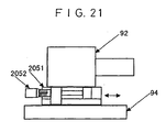
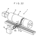
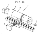
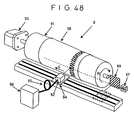
- FIG. 61 shows an example of an imaging apparatus using beam irradiation sources such as laser beam source.
- an imaging apparatus 9 comprises a medium support drum 91 for winding an imaging medium around on its outer surface, an imaging head 92 including beam irradiation sources and an optical system for condensing beams from the beam irradiation sources, a beam irradiation source control unit 96, and a cable 95 for connecting the imaging head 92 to the beam irradiation source control unit 96.
- the imaging head 92 is fixed onto a linear stage 94 for realizing a parallel movement with respect to an axial direction of the medium support drum 91.
- a linear motor typed linear stage which is directly driven by a linear motor, and a ball screw typed linear stage using a ball screw typed linear guide are generally used.
- the distance between the imaging head 92 and the imaging medium 98 is adjusted such that the beams are condensed on the surface of the imaging medium.
- the outputs of the beam irradiation sources are controlled enough to generate a change in an imaging characteristic (physical change) such as projections and depressions according to imaging data or a change in solubility to solvent between a beam irradiation section of the imaging medium 98 and a non-irradiation section.
- the beam irradiation sources are switched to correspond to imaging data as performing the following operations. Specifically, the medium support drum 91 around which the imaging medium 98 is wound is rotated in a direction of an arrow R of the figure using a motor 93 such as a pulse motor. Also, the imaging head 92 fixed onto the linear stage 94 is moved in a direction of an arrow S of the figure to be parallel to the shaft of the medium support drum. This generates a two-dimensional change in an imaging characteristic (physical change), such as physical projections and depressions according to imaging data or a change in solubility to solvent, on the surface of the imaging medium.
- an imaging characteristic physical change
- a direction R of lines imaged by the rotation of the medium support drum 91 is defined as a main scanning direction
- a direction S of lines imaged by the parallel movement of the imaging head 92 is defined as a sub-scanning direction.
- the plurality of beam irradiation sources which can be independently driven.
- the improvement of the performance of the imaging apparatus means to enhance the imaging speed and resolution.
- the relationship of tradeoff is established between the imaging speed and the resolution.
- the resolution denotes that how many dots can be formed per unit length, and dpi (dots per inch) is generally used as a unit.
- 2540 dpi corresponds to 100 dots/mm.
- the imaging head having i beam irradiation sources is used to execute imaging i lines continuous to the main scanning direction simultaneously by i beam irradiation sources.
- a dot distance d p for realizing a predetermined resolution r is 1/r.
- the imaging head is moved by a predetermined distance after the imaging corresponding to one circumference in the main scanning direction is finished.
- the ball screw typed linear stage is used, the imaging head is moved by a predetermined distance during one turn of the medium support drum.
- the predetermined distance is i times as large as the dot distance d p on the imaging medium.
- next i lines are imaged, and these series of operations are repeated, and the imaging of the entire surface of the imaging area is completed.
- i beam irradiation sources By use of i beam irradiation sources, the time required for imaging is reduced to 1/i when the resolution is the same.
- a laser diode array is used as one of the methods using the plurality of beam irradiation sources.
- the general outline view is shown in FIG. 39 .
- a laser diode array 8 includes eight laser diodes, which can be independently driven, in one chip.
- the laser diodes have laser beam emission ends 81a to 81h, drive side electrodes 82a to 82h, and a rear face common electrode 83 for all laser diodes, respectively.
- the flow of a predetermined current to the drive side electrodes 82a to 82h allows the laser beam to be emitted from the corresponding laser beam emission ends 81a to 81h.
- the predetermined current means a current value of more than a threshold value at which the laser diode starts the laser oscillation.
- the fiber array is used as another method using the plurality of beam irradiation sources.
- the outline view of a fiber output laser apparatus is shown in Fig. 42 .
- a laser apparatus 6 comprises a laser diode chip having at least one light emission end, a conductive member for realizing the electrical contact between an electrode of the diode chip and an outer unit, a package section 61 having a heat conduction member for escaping heat from the diode chip to the outside and an optical system for making the laser beams incident onto the optical fibers from the laser diode, and an optical fiber 62 for guiding laser beams to the outer unit.
- the laser beam is emitted from an emission end 63 of the optical fiber 62.
- the emission end 63 of the optical fiber 62 has a core portion 64 and a clad portion 65, and the laser beam is output from the core portion 64.
- the emission ends 63 of the plurality of fibers of the laser device of the plurality of fiber outputs are arranged in an array form and fixed, thereby structuring the fiber array.
- the maximum distance between the beam irradiation sources is restricted by an outside dimension of the clad portion 65.
- An array 7 comprises eight beam irradiation sources 71a to 71h, and its inclination angle ⁇ is defined by the following equation (1).
- a s is a distance between the beam irradiation sources
- a light source surface dot distance d s obtained by converting the central distance between dots, which should be formed to obtain a predetermined resolution in the sub-scanning direction S, to the dimension at the beam irradiation source surface
- the medium surface dot distance d p is divided by a magnification of the optical system.
- d p 10 ⁇ m when resolution is 2540 dpi
- d s 40 ⁇ m when the magnification of the optical system is 1/4.
- the beam diameter is larger than the dot distance d p. preferably about ⁇ 2 times in order to make it possible completely image the entire surface of the imaging area.
- Unexamined Japanese Patent Publication No. 5-16320 is known as one of the methods for improving the response of the laser beam sources so as to accelerate the imaging speed.
- a current is made to flow to a value close to a threshold value at which the laser beam sources actuate. Then, in the laser beam sources, time required for switching an imaging data absent state to an imaging data present is reduced.
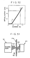
- FIG. 50 shows one example of a characteristic of current-optical output in the laser diode.
- a current value at which the optical output is started to rise is a threshold current I th
- a current value at which the imaging is actually executed is an operation current I on .
- an optical output P on emitted from the laser beam source is an output enough to generate a change in an imaging characteristic between the laser beam irradiation section of the imaging medium and the no-irradiation section thereof.
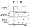
- 62 shows a control signal to be transmitted to a laser diode from a laser beam source driving circuit in the laser beam source control unit, a current value flowing to the laser diode, and a change in the optical output emitted from the laser beam source, respectively, at an imaging operation time.
- Unexamined Japanese Patent Publication No. 5-16320 discloses a method for changing the current value at the imaging data absent time to an extent of the threshold current of the semiconductor laser.
- the semiconductor laser beam may be generated if the extent of laser power such that no depression is formed in a plate at the imaging data absent time.
- the above specification does not describe the specific numeral value of what extent of the range is allowable.
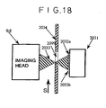
- FIGS. 63A and 63B show examples of a method for manufacturing an optical fiber array used in the above-mentioned imaging apparatus.
- a V-shape groove corresponding to the number of optical fibers is formed in an optical fiber support member 3012 so that the optical fibers are arranged in the V-shaped groove. Then, the optical fibers are pressed from the upper portion by a pressing member 3013, and a space between the optical fibers is filled with adhesive to be hardened and combined as one unit.
- a fixed groove whose width corresponds to the number of optical fibers is formed in the optical fiber support member 3012 so that the optical fibers are arranged in the fixed groove. Then, the optical fibers are pressed from the upper portion by the pressing member 3013, and a space between the optical fibers is filled with adhesive to be hardened and combined as one unit.
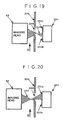
- the optical fiber apparatus can be arranged in a direction parallel to the sub-scanning direction as in FIG. 64A without being inclined at a predetermined angle as shown in FIG. 64B .
- the linear motor drive stage be used.
- the rearrangement of data means a process for adjusting the case in which lines discontinuous to the sub-scanning direction are imaged simultaneously in executing the above-mentioned feeding of the sub-scanning.
- the manufacturing method of the optical fiber array apparatus in this case is the same as the above-mentioned method, that is, an angle may be changed when the optical fiber array apparatus may be incorporated into the imaging head.
- the imaging head apparatus using the laser beam sources of the optical fiber array type in which all optical fiber emission ends are arranged in a straight line, it is required that all laser beams be satisfactorily condensed on the imaging medium.
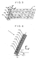
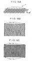
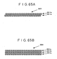
- FIGS. 65A and 65B show examples of the array method of the optical fiber emission ends.
- FIG. 65A is a two-row array like a barrel piling
- FIG. 65B is a three-row array of vertical piling.
- the two-row array like a barrel piling is that a second optical fiber array is arranged on a first optical fiber array such that the pitch of the emission ends becomes the same as the first optical fiber row.
- the first optical fiber row is formed such that the emission ends of the optical fibers are arrayed with a predetermined pitch.
- the two-row array like a barrel piling is formed such that the shift in the array direction between the first optical fiber row and the second optical fiber row becomes 0.5 times as large as the predetermined pitch.
- the convex portions of the other optical fiber row enter the concave portions of one optical fiber row, which are formed since the optical fibers are substantially columnar shape. Thereby, both fiber rows are closely contacted to each other. In the array of vertical piling, there is no shift of the optical fiber rows.
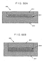
- the manufacturing method of the optical fiber array is basically the same as the above-mentioned method.
- an optical fiber fixed groove having a width corresponding to the size which is one larger than the number of optical fibers, is formed in the optical fiber support member 3012. Then, the optical fiber row of the first stage and a dummy fiber 3014 are arranged in the fixed groove. Then, the optical fiber row of the second stage is arranged thereon, and pressed from the upper portion by the pressing member 3013, and the space therebetween is filled with adhesive to be hardened and combined as one unit.
- an optical fiber fixed groove having a width corresponding to the number of optical fibers, is formed in the optical fiber support member 3012. Then, the optical fiber row of the first stage is arranged in the fixed groove. Then, the optical fiber of the second stage is arranged thereon through a spacer 3018, and the optical fiber of the third stage is arranged thereon through the space 3018 again. Finally, the optical fibers are pressed from the upper portion by the pressing member 3013, and the space therebetween is filled with adhesive to be hardened and combined as one unit.
- the dummy fiber 3014 in the two-row array like a barrel piling and the spacer 3018 in the three-row array of vertical piling are used to stabilize the position of the fibers.
- the apparatus in which the plurality of the beam irradiation sources are arranged in an array form, the following problems are present. More specifically, when at least one of the beam irradiation sources is out of order, the apparatus cannot be completely operated until the entire array or the entire imaging head is repaired or replaced. Moreover, when the plurality of beam irradiation sources is formed in the same semiconductor chip at the time of manufacturing the imaging head, all beam irradiation sources become defective if at least one of the beam irradiation sources becomes defective because of local defectiveness in the semiconductor chip. This reduces yield of the imaging head. When the number of beam irradiation sources per one imaging head is increased to improve the performance of the imaging apparatus, the above-mentioned problems become more conspicuous.
- the threshold current value I th at which the laser beam sources actuate is considerably smaller than the operation current I on for obtaining outputs enough to generate a change in the imaging characteristic (physical change) such as a change in the physical shape of the imaging medium or a change in solubility to solvent. For this reason, there is a problem in which a reduction in switching time is not largely expected.
- the distance between the imaging head including the laser beam sources and the imaging medium must be delicately adjusted. It takes much time to condense the beams on the surface of the imaging medium satisfactorily so as to execute a good imaging.
- the actual adjustment is a trial-and-error work. Specifically, the imaging result is observed by a magnifying glass, the distance is adjusted by focal adjusting means based on the observation result, and the imaging is executed again. Moreover, the determination cannot be made only by the imaging result, depending on the imaging medium.
- the estimation can be often performed only after the imaging medium is used as a press plate and the printing is executed. In this case, the imaging post-process and the printing process are further needed. Moreover, the cost and time are required.
- the optical axis of the optical fibers on the second stage (upper stage) in the sub-scanning direction is positioned at just the center of the optical axis of the optical fibers on the first stage (lower stage).
- resolution which is twice as high as the horizontal array of one row, can be obtained.
- the clad diameter must be reduced to a value close to a core diameter.
- imaging data must be rearranged after adding contrivance to the sub-scanning method as mentioned above.
- the optical fiber array In the array of vertical piling shown in FIG. 65B , the optical fiber array must be inclined at a predetermined angle such that the projection distance between the optical fiber arrays to the sub-scanning direction is constantly maintained.
- the shift amount of each optical array in the sub-scanning direction is defined by only the inclination angle, and the shift of each stage can be neither defined and nor adjusted individually. Therefore, it is difficult to manufacture the optical fiber array having an excellent positional accuracy.
- an optical fiber array apparatus as defined in claim 1, an imaging head apparatus as defined in claim 4 and an imaging apparatus as defined in claim 5.
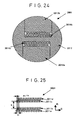
- FIG. 24 shows an example of the optical fiber array apparatus of the present invention.
- FIG. 25 shows the arrangement of the optical fiber emission ends.
- An optical fiber array apparatus 3001 comprises four optical fiber rows (3011a to 3011d) in which 10 optical fiber emission ends are arranged in a straight line.
- an optical fiber double row 3011ab having the optical fiber rows 3011a, 3011b, and an optical fiber double row 3011cd having the optical fiber rows 3011c, 3011d are structured to have the array of two rows (like a barrel piling), respectively.
- each optical fiber row 10 optical fiber emission ends are arranged in a straight line with a distance of a s .
- the array direction of the optical fiber emission ends included in each optical fiber row is provided to be parallel to the sub-scanning direction (a projection direction to the main scanning direction forms 90° to the array direction).
- the optical fiber row 3011b is shifted by ⁇ 3a s /2 in the main scanning direction and a s /2 in the sub-scanning direction.
- the optical fiber row 3011c is shifted by ⁇ 3a s /2+b in the main scanning direction and a s /4 in the sub-scanning direction.
- the optical fiber row 3011d is shifted by in the main scanning direction and 3a s /4 in the sub-scanning direction.
- b is about 3 to 5 times as large as as.
- the number of optical fibers emission ends of one optical fiber row is 10. However, if the number of optical fibers emission ends is two or more, any number is possible. The favorable range is 8 to 32.
- the entire imaging area can be imaged without inclining the optical fiber array apparatus with respect to the sub-scanning direction as shown-in FIG. 6 .
- the good image area which is required for the optical system, can be reduced to an extent that the length of one optical fiber row is sufficiently included as compared with the case in which all optical fiber emission ends are arranged in a straight line and the case in which the optical fiber emission ends are arranged in two rows. Therefore, a large amount of optical fiber emission ends can be arranged without increasing the cost of the optical system and the size thereof.
- the shift amount of the optical fiber emission ends in the main scanning direction can be reduced to , many optical fiber emission ends can be arranged without complicating the electric circuit for controlling timing of imaging with the shift or without increasing the manufacturing cost. In this case, contrivance of the sub-scanning method and the rearrangement of data are not necessarily needed.
- the positional deviation in the array direction between one optical fiber row and the other optical fiber rows can be accurately and easily set to be 0. 5 times as large as the optical fiber pitch.
- FIGS. 26A to 26E The manufacturing process will be shown in FIGS. 26A to 26E .
- a columnar material 3019 made of stainless and so on for forming an optical fiber support member, is prepared.
- a fiber fixing groove having a width where (n +1) optical fibers are arranged, is formed in upper and lower portions by wire discharge process etc. , so as to manufacture an optical fiber support member 3017.
- the material 3019 uses all the same material.
- the bottom surfaces serve as parallel portions 3015a and 3015b, and side surfaces serve as restricting portions 3016a to 3016d.
- the parallel portions 3015a and 3015b are precisely processed to be parallel to each other.
- the restricting portions 3016a to 3016d are precisely processed such that the shift of the optical fiber array direction between the restricting portions 3016a and 3016c and the shift of the optical fiber array direction between the restricting portions 3016b and 3016d are 3a s /4.
- the optical fiber row 3011b having n optical fibers and one dummy fiber 3014a whose diameter is equal to the optical fiber serving as the light source are arranged as follows. More specifically, they are arranged in the parallel portion 3015a such that the optical fiber positioned at the left edge is closely in contact with the restricting portion 3016a and the right edge of the dummy fiber 3014a is closely in contact with the restricting portion 3016b.
- the optical fiber row 3011a having n optical fibers is arranged on the optical fiber row 3011b having n optical fibers and one dummy fiber 3014a in a barrel-piling manner.
- a pressing member 3013a is pressed thereon, and upper and lower portions are inverted as shown in FIG. 26D .
- the optical fiber row 3011c having n optical fibers and one dummy fiber 3014b are arranged, and the optical fiber row 3011d having n optical fibers is arranged thereon in the same manner as shown in FIG. 26C .
- a pressing member 3013b is pressed thereon, and the space is filled with adhesive to be hardened so that the above mentioned members are combined into one.
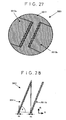
- FIG. 27 Another example of the optical fiber array apparatus of the present invention is shown in FIG. 27 .
- the array of the optical fiber emission ends is shown in FIG. 28 .
- the optical fiber array apparatus 3001 comprises two optical fiber rows (3011a and 3011b) in which 20 optical fiber emission ends are arranged in a straight line.
- each optical fiber row 20 optical fiber emission ends are arranged in a straight line with a distance of a s .
- the array direction of the optical fiber emission ends included in each optical fiber row is provided to have a predetermined angle ⁇ with respect to the sub-scanning direction S (an angle to be formed with respect to the array direction of the projection direction is (90° - ⁇ )).
- the angle 6 is defined as in equation (1).
- the optical fiber 3011b is shifted by 0 in the main direction and 20 d s in the sub-scanning direction.
- the number n of optical fibers emission ends of one optical fiber row is 20.
- the number of optical fibers emission ends is two or more, any number is possible.
- the favorable range is 8 to 32.
- the good image area which is required for the optical system, can be reduced to an extent that the length of one optical fiber row is sufficiently included as compared with the case in which all optical fiber emission ends are arranged in a straight. Therefore, a large amount of optical fiber emission ends can be arranged without increasing the cost of the optical system and the size thereof. Since the shift amount of the optical fiber emission ends in the main scanning direction can be reduced to a half, many optical fiber emission ends can be arranged without complicating the electric circuit for controlling timing of imaging with the shift or without increasing the manufacturing cost.
- the method for manufacturing the optical fiber array apparatus 3001 with a good positional accuracy of the optical fiber emission ends is basically the same as the manufacturing process shown in FIGS. 26A to 26E .
- the differences therebetween are the formation of only one optical fiber row in one fiber fixing groove and the positional relationship between the parallel portions and the restricting portions.
- the fiber fixing groove has a width where n optical fibers can be arranged.
- the distance between the parallel portions is precisely processed to be a s (nsin ⁇ cos ⁇ -1), and the shift between the restricting portions is also precisely processed to be as cos 2 ⁇ .
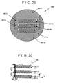
- FIG. 29 Another example of the optical fiber array apparatus of the present invention is shown in FIG. 29 .
- the array of the optical fiber emission ends is shown in FIG. 30 .
- the optical fiber array apparatus 3001 comprises six optical fiber rows (3011a and 3011f) in which 10 optical fiber emission ends are arranged in a straight line.
- each optical fiber row 10 optical fiber emission ends are arranged in a straight line with a distance of a s .
- the array direction of the optical fiber emission ends included in each optical fiber row is formed to be parallel to the sub-scanning direction.
- the optical fiber row 3011b is shifted by 3a s /2 in the main scanning direction and a s /2 in the sub-scanning direction.
- the optical fiber row 3011c is shifted by in the main scanning direction and a s /6 in the sub-scanning direction.
- the optical fiber row 3011d is shifted by in the main scanning direction and 2a s /3 in the sub-scanning direction.
- the optical fiber row 3011e is shifted by in the main scanning direction and a s /3 in the suh-scanning direction.
- the optical fiber row 3011f is shifted by 3a s /2+2b in the main scanning direction and 5a s /6 in the sub-scanning direction. In this case, b is about 1 to 5 times as large as as.
- the number n of optical fibers emission ends of one optical fiber row is 10. However, if the number of optical fibers emission ends is two or more, any number is possible.
- the favorable range is 8 to 32.
- the entire imaging area can be imaged without inclining the optical fiber array apparatus as shown in FIG. 6 .
- the good image area which is required for the optical system, can be reduced to an extent that the length of one optical fiber row is sufficiently included as compared with the case in which all optical fiber emission ends are arranged in a straight line and the case in which the optical fiber emission ends are arranged in two rows. Therefore, a large amount of optical fiber emission ends can be arranged without increasing the cost of the optical system and the size thereof.
- the shift amount of the optical fiber emission ends in the main scanning direction can be reduced to . For this reason, many optical fiber emission ends can be arranged without complicating the electric circuit for controlling timing of imaging with the shift or without increasing the manufacturing cost. In this case, contrivance of the sub-scanning method and the rearrangement of data are not necessarily needed.
- FIGS. 31A to 31E The manufacturing process will be shown in FIGS. 31A to 31E .
- the columnar material 3019 for forming an optical fiber support member is prepared.
- a two-stage groove is formed by wire discharge process etc., so as to manufacture an optical fiber support member 3017a.
- the two-stage groove is formed such that a bottom portion has a width where (n +1) optical fibers can be arranged and an opening portion has a width equal to the widths of optical fiber arranging members 3017b and 3017c.
- the optical fiber arranging members 3017b and 3017c have fiber fixing grooves each having a width where (n +1) optical fibers can be arranged.
- the optical fiber support member 3017a and the optical fiber arranging members 3017b and 3017c are combined into one to be described later, and function as an optical fiber support member.
- the bottom surface of the groove of the support member 3017a functions as the parallel portion 3015a
- the bottom surfaces of the fiber fixing grooves of the arranging member 3017b and 3017c function as the parallel portions 3015b and 3015c.
- the side surface of the groove of the support member 3017a functions as restricting portions 3016a and 3016b
- the side surfaces of the grooves of the optical fiber arranging members 3017b and 3017c function as restricting portions 3016c to 3016f.
- the parallel portions 3015a to 3015c are precisely processed to be parallel to each other.
- the respective portions 3016a to 3016f are precisely processed such that the shift of the optical fiber array direction between the restricting portions 3016a, 3016c, 3016e and the restricting portions 3016b, 3016d, 3016f is a pitch of a s /6.
- the optical fiber row 3011a having n optical fibers and one dummy fiber 3014a whose diameter is equal to the optical fiber serving as the light source are arranged as follows. More specifically, they are arranged in the parallel portion 3015a such that the optical fiber positioned at the left edge is closely in contact with the restricting portion 3016a and the dummy fiber 3014a is closely in contact with the restricting portion 3016b.
- the optical fiber row 3011b having n optical fibers is arranged on the optical fiber row 3011a having n optical fibers and one dummy fiber 3014a in a barrel-piling manner.
- the optical fiber arranging member 3017b is pressed thereon, the optical fiber row 3011c having n optical fibers and one dummy fiber 3014b whose diameter is equal to the optical fiber serving as the light source are arranged in the parallel portion 3015a. Then, the optical fiber positioned at the left edge is closely in contact with the restricting portion 3016c and the dummy fiber 3014b is closely in contact with the restricting portion 3016d. Moreover, the optical fiber row 3011d having n optical fibers is arranged on these optical fibers in a barrel-piling manner.
- the optical fiber arranging member 3017c, the optical fiber row 3011e having n optical fibers and one dummy fiber 3014c are arranged, and the optical fiber row 3011f having n optical fibers is arranged thereon in the same manner as shown in FIG. 31D .
- the pressing member 3013 is pressed thereon, and the space is filled with adhesive to be hardened so that the above members are combined into one.
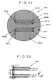
- FIG. 32 Another example of the optical fiber array apparatus of the present invention is shown in FIG. 32 .
- the array of the optical fiber emission ends is shown in FIG. 33 .
- the optical fiber array apparatus 3001 comprises four optical fiber rows (3011a and 3011d) in which 10 optical fiber emission ends are arranged in a straight line. Spacers 3018a and 3018b each having a predetermined thickness are provided between the optical fiber rows 3011a and the 3011b and between the optical fiber rows 3011c and 3011d, respectively.
- each optical fiber row 10 optical fiber emission ends are arranged in a straight line with a distance of as.
- the array direction of the optical fiber emission ends included in each optical fiber row is formed to be parallel to the sub-scanning direction.
- the optical fiber row 3011b is shifted by c in the main scanning direction and a s /2 in the sub-scanning direction.
- the optical fiber row 3011c is shifted by c+b in the main scanning direction and a s /4 in the sub-scanning direction.
- the optical fiber row 3011d is shifted by 2c+b in the main scanning direction and 3a s /4 in the sub-scanning direction.
- b is about 3 to 5 times as large as a s
- c is a sum of the clad diameters of the fibers and the thickness of the spacers.
- the number of optical fibers emission ends of one optical fiber row is 10. However, if the number of optical fibers emission ends is two or more, any number is possible.
- the favorable range is 8 to 32.
- the entire imaging area can be imaged without inclining the optical fiber array apparatus as shown in FIG. 6 .
- the good image area which is required for the optical system, can be reduced to an extent that the length of one optical fiber row is sufficiently included as compared with the case in which all optical fiber emission ends are arranged in a straight line and the case in which the optical fiber emission ends are arranged in two rows. Therefore, a large amount of optical fiber emission ends can be arranged without increasing the cost of the optical system and the size thereof.
- the shift amount of the optical fiber emission ends in the main scanning direction can be reduced to 2c+b. For this reason, many optical fiber emission ends can be arranged without complicating the electric circuit for controlling timing of imaging with the shift or without increasing the manufacturing cost. In this case, contrivance of the sub-scanning method and the rearrangement of data are not necessarily needed.
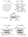
- FIGS. 34A to 34E The manufacturing process will be shown in FIGS. 34A to 34E .
- the columnar material 3019 for forming an optical fiber support member is prepared.
- a two-stage fiber fixing groove is formed in upper and lower portions by wire discharge process etc., so as to manufacture an optical fiber support member 3017.
- a width of the first-stage of the two-stage fiber fixing groove is such that n optical fibers can be arranged, and a width of the second-stage thereof is such that (n+1) optical fibers can be arranged.
- the bottom surface of the fiber fixing groove functions as the parallel portions 3015a and 3015b.
- the first-stage side surfaces 3016a, 3016b, 3016e, 3016f and the second-stage side surfaces 3016c, 3016d, 3016g, 3016h function as restricting portions. For this reason, the parallel portions 3015a and 3015c are precisely processed to be parallel to each other.
- the restricting portions 3016a to 3016h are precisely processed such that the shift of the optical fiber array direction among the restricting portions 3016a, 3016c, the restricting portions 3016b, 3016d, the restricting portions 3016e and 3016g, and the restricting portions 3016f and 3016h are set to a s /2 and that the shift of the optical fiber array direction between the restricting portions 3016a, 3016e and the restricting portions 3016b, 3016f is set to a s /4.
- the optical fiber row 3011b having n optical fibers is arranged in the parallel portion 3015a such that the optical fiber positioned at the left edge is closely in contact with the restricting portion 3016a and the optical fiber positioned at the right edge is closely in contact with the restricting portion 3016b.
- a spacer 3018a is mounted on the optical fiber row 3011b having n optical fibers.
- the optical fiber row 3011a having n optical fibers and one dummy fiber 3014a whose diameter is equal to the optical fiber serving as the light source are arranged such that the left edge of the dummy fiber 3014a is closely in contact with the restricting portion 3016c and the optical fiber positioned at the right edge is closely in contact with the restricting portion 3016d.
- the pressing member 3013a is pressed thereon, and upper and lower portions are inverted as shown in FIG. 34D . Thereafter, the optical fiber row 3011c having n optical fibers, the spacer 3018b are arranged, and the optical fiber row 3011d having n optical fibers and one dummy fiber 3014b are arranged thereon in the same manner as shown in FIG. 34C . Finally, as shown in FIG. 34E , the pressing member 3013b is pressed thereon, and the space is filled with adhesive to be hardened so that the above members are combined into one.
- FIG. 35 Another example of the optical fiber array apparatus of the present invention is shown in FIG. 35 .
- the array of the optical fiber emission ends is shown in FIG. 36 .
- the optical fiber array apparatus 3001 comprises 10 optical fiber rows (3011a and 3011j) in which four optical fiber emission ends are arranged in a straight line. In each optical fiber row, four optical fiber emission ends are arranged in a straight line to have a distance and an angle such that the projection in the sub-scanning direction becomes a s /4.
- the optical fiber row 3011b is shifted by a s in the sub-scanning direction.
- the optical fiber row 3011c is shifted by 2a s in the sub-scanning direction.
- the optical fiber row 3011d is shifted by 3a s -, and the optical fiber row 3011j is shifted by 9a s in the sub-scanning direction.
- the number of optical fiber emission ends of one optical fiber row is four. Actually, two to eight optical fiber emission ends are practically used, and the most favorable number of optical fiber emission ends is four.
- the entire imaging area can be imaged without inclining the optical fiber array apparatus as shown in FIG. 6 .
- the good image area which is required for the optical system, can be reduced to an extent that the length of one optical fiber row is sufficiently included as compared with the case in which all optical fiber emission ends are arranged in a straight line and the case in which the optical fiber emission ends are arranged in two rows. Therefore, a large amount of optical fiber emission ends can be arranged without increasing the cost of the optical system and the size thereof.
- the shift amount of the optical fiber emission ends in the main scanning direction can be reduced to be below three times as large as the clad diameter of the fiber. For this reason, many optical fiber emission ends can be arranged without complicating the electric circuit for controlling timing of imaging with the shift or without increasing the manufacturing cost. In this case, contrivance of the sub-scanning method and the rearrangement of data are not necessarily needed. Since the array of the optical fiber emission ends can be made compact in the above-mentioned embodiments, a good image range necessary for a lens can be minimized.
- the optical fiber single row is inserted to each slit of the comblike optical fiber support member, but the optical fiber double row may be inserted.
- the optical fiber double row may be inserted.
- FIG. 37 shows an enlarged view of the fiber support portion of a comblike optical fiber support member 3027, which makes it possible to manufacture the optical fiber array apparatus with a good accuracy of the optical fiber emission ends.
- comblike grooves are formed in the fiber support portion of the comblike optical fiber support member 3027. More specifically, the comblike grooves are formed by wire discharge process so as to have a width where one optical fiber can arranged and a depth corresponding to the number of fiber emission ends of one fiber row. The number of comblike grooves corresponds to that of fiber rows.
- the bottom surface of the fiber fixing groove functions as the restricting portions 3016a, 3016b, 3016c, -, 3016j.
- the side surface functions as parallel portions 3015a, 3015b, 3015c, ..., 3015t.
- the parallel portions 3015a, 3015b, 3015c, ..., 3015t are precisely processed so as to be all parallel to each other.
- the restricting portions 3016a to 3016j are precisely processed such that the shift in the main scanning direction becomes 0, and that the distance between the adjacent restricting portions in the sub-scanning direction becomes as, and that the width of the groove ranges 1.012 to 1.020 times as large as the optical fiber diameter.
- the actual manufacturing method is as follows. More specifically, 40 fibers are closely arranged at the fiber support portion of the comblike fiber support member 3027, and the pressing member 3013 is pressed thereon. Then, the space is filled with adhesive to be hardened so that the above members are combined into one, thereby the manufacture of the comblike fiber support member can be realized.
- the comblike fiber support member 3027 can provide a pair of parallel portions substantially closely contacting both sides of each optical fiber row. Therefore, the position of the direction intersecting at right angles with the parallel portions of the respective optical fibers can be restricted, so that the positioning can be extremely easily carried out.
- the comblike fiber support member 3027 is formed as one body.
- the comblike fiber support member 3027 can be formed by alternatively stacking branch-like members having a different length on top of each other.
- the imaging head apparatus of the present invention can be realized as the imaging head 92 having the optical fiber array 3001 as explained above.
- the following will shows an example of the array of the beam irradiation sources in the imaging head 92 of the imaging apparatus 9.
- the laser diode array and the fiber array are used, and each means will be explained as follows.
- the beam irradiation sources are formed in the laser diode array 8 as shown in FIG. 39 .
- the laser diode array 8 is formed of a GaAs compound semiconductor. Specifically, eight laser diodes, which can be independently driven, are formed in one chip.
- the laser diodes have laser beam emission ends 81a to 81h, drive side electrodes 82a to 82h, and the rear face common electrode 83 for all laser diodes, respectively.
- the laser beam emission ends are used as beam irradiation sources.
- the number of laser diodes included in the laser diode chip is generally referred to as a channel number.
- a predetermined current means a current value of more than a threshold value at which the laser diode starts the laser oscillation. More specifically, the threshold current is about 0.2 to 0.6A, and the actual operation current is about 0.7 to 1.3A.
- the widths of the respective laser beam emission ends are about 80 to 120 ⁇ m and the distance therebetween is about 150 to 250 ⁇ m.
- the distance between the electrodes on the driving side is the same extent as the above.
- the widths of the laser beam emission ends are the sizes, which are necessary for obtaining the above extent of high outputs.
- the distance between the laser beam emission ends and the distance between the electrodes on the driving side are the distance, which is necessary for selectively supplying the current when the laser diodes are operated.
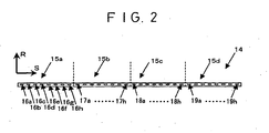
- the first array method is as follows. More specifically, all beam irradiation sources are formed in the same semiconductor chip, and the light source blocks are arrayed in the same direction as the direction where the beam irradiation sources of the block are arranged, and the structure as shown in FIG. 2 is formed.
- the laser diode array 8 of FIG. 39 eight beam irradiation sources are included in one semiconductor chip. In the above case, 32 beam irradiation sources are prepared in one chip, and divided into four light source blocks A to D (15a to 15d). In this case, eight beam irradiation sources are included in one light source block.
- the laser diode array is inclined by a predetermined angle ⁇ as shown is Fig. 6 . If imaging resolution is 2540 dpi, the dot distance d p on the imaging medium is 10 ⁇ m. If the magnification of the optical system is 1/5, the dot distance d s at the light source surface is 50 ⁇ m, and the distance a s between the beam irradiation sources is 200 ⁇ m. Then, the angle ⁇ becomes 75.5° from equation (1).
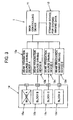
- the block A (15a) and the beam irradiation source driving device A (13a) are separated from each other. Then, software for outputting imaging data of the main control device 11 is changed from software for all four blocks to one for three blocks, and blocks B to D (15b to 15d) are used. This reduces the imaging speed to 3/4, but the imaging operation can be continued without stopping the apparatus.
- the optical system incorporated into the imaging head is designed such that the beams sent from all light source blocks can be condensed in the same manner so as to condense the beams emitted from the beam irradiation sources onto the imaging medium. For this reason, the mechanical readjustment of the optical system is not needed. Also, the feed amount of the linear stage in the sub-scanning direction at the time of imaging operation may be changed from 320 ⁇ m (10 ⁇ m X 32) for four blocks to 240 ⁇ m (10 ⁇ m X 24) for three blocks.
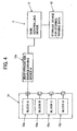
- the imaging head using the above array can be applied to the imaging apparatus in which the imaging speed is restrained. More specifically, as shown in FIG. 4 , if only one beam irradiation source driving device is connected in order to use the block A of four blocks, the imaging head can be directly applied. At this time, the number of expensive beam irradiation driving devices may be one, the electric circuit of the main control device and the software can be simplified, so that the cost reduction can be realized.
- FIGS. 40 and 41 One example of the mounting method will be shown in FIGS. 40 and 41 .
- a laser diode array mounting unit 5 comprises a heat diffusion member 51 of thermal conductivity for escaping heat generated in the laser diode array to a heat sink of an outer unit, a main mounting plate 52, sub-mounting plate adjusting screws 53a to 53d, sub-mounting plates 54a to 54d, a terminal fixing plate 55, and electrode extracting terminals 56a to 56h, 57a to 57h, 58a to 58h, 59a to 59h.
- FIG. 40 is a view seeing from a direction of the emission ends of the laser beam source
- FIG. 41 is a view seeing from the drive electrode side of the laser diode array.
- These figures show only the sub-mounting plate adjusting screw 53d, the sub-mounting plate 54d, and the electrode extracting terminals 56a to 56h, which are provided at an uppermost portion.
- the sub-mounting plate adjusting screws 53a to 53c, the sub-mounting plates 54a to 54c, and the electrode extracting terminals 56a to 56h, 57a to 57h, 58a to 58h, 59a to 59h are provided at the similar position of the lower portion.
- the main mounting plate 52 is L-shaped.
- the main mounting plate 52 has a groove for fixing the sub-mounting plates 54a to 54d such that the position of the beam irradiation sources of the laser array in the main scanning direction is set to have a predetermined space (e.g., 1 mm).
- the sub-mounting plate adjusting screws 53a to 53d are provided therein.
- the laser diode array is die-bonded to the sub-mounting plates 54a to 54d formed of material having a good thermal conductivity and electrical conductivity such that the back face common electrode ohmic-contacts.
- the sub-mounting plate 54a to which the laser diode array is die-bonded is set to the main mounting plate formed of material having a good thermal conductivity and electrical conductivity.
- the conductive electrode extracting terminals 56a to 56h are set to the insulating terminal fixing plate 55.
- the drive side electrode 82a of the laser diode array 8 and the electrode extracting terminal 56a, the drive side electrode 82b and the electrode extracting terminal 56b, ... and the drive side electrode 82h and the electrode extracting terminal 56h are wire-bonded by wires 84a to 84h, respectively.
- the sub-mounting plate 54b to which the laser diode array is die-bonded is set to the main mounting plate.
- the laser diodes of edge surface emission are layered so as to realize the two-dimensional array of the beam irradiation sources.
- the similar two-dimensional array can be realized by use of a surface emission laser.
- the array of the beam irradiation sources can be realized by the optical system using optical parts such as a prism.
- An imaging head 3 comprises four laser diode arrays 31a to 31d including eight laser diodes, four individual optical systems 32a to 32d for carrying out a conversion of emission light of each laser diode array to parallel light and a slight adjustment of the laser beam position, a polarizing prism 33 having a surface 37 whose reflectance and transmittance are largely different depending on S polarization and P polarization in its interior, a miniature optical system 34, and two heat diffusion members 35a to 35b.
- the respective laser diode arrays 31a to 31d have the structure as shown in FIG. 39 , and the distance between the laser diodes therein is 200 ⁇ m.
- the laser diode arrays 31a to 31d are mounted on the heat diffusion member 35a such that the emission ends of the respective laser diodes are arranged in a direction perpendicular to paper as shown in FIG. 41 .
- a predetermined current is made to flow to each driving side electrode, so that the laser beam of S polarization is emitted to the surface 37.
- the laser diode arrays 31b and 31d are mounted on the heat diffusion member 35b. Then, a predetermined current is made to flow to each driving side electrode, so that the laser beam of P polarization is emitted to the surface 37.
- the laser beams emitted from the laser diode arrays 31a and 31c are converted to parallel light by the individual optical systems 32a and 32c, and the parallel light enters the interior of the prism from a surface 36a of the polarizing prism 33.
- the laser beams emitted from the laser diode arrays 31b and 31d are converted to parallel light by the individual optical systems 32b and 32d, and the parallel light enters the interior of the prism from a surface 36b of the polarizing prism 33.
- the laser beams of S polarization that is, the laser beams emitted from the laser diode arrays 31a and 31c are reflected at the surface 37 of the prism.
- the laser beams of P polarization that is, the laser beams emitted from the laser diode arrays 31b and 31d are transmitted through the surface 37 of the prism, and are finally emitted to the outer unit from the surface 36c.
- the positions of the laser beams 38a to 38d at the surface 36c are shown in FIG. 47 .
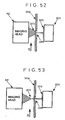
- FIG. 42 is an outline view of a laser apparatus for a fiber output.
- the laser apparatus 6 comprises a package portion 61 and an optical fiber 62.
- the package portion 61 contains the laser diode chip and the optical system for making the laser beams incident onto the optical fiber from the laser diode.
- the optical fiber 62 guides the laser beam to the outer unit. Then, the laser beam is emitted from a fiber emission end 63. Then, the fiber array is formed by arranging the plurality of fiber emission ends 63 in an array form using the plurality of laser apparatus for a fiber output.
- the beam irradiation sources in the present invention indicate the emission ends 63.
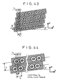
- the first array method is shown in FIG. 43 .
- number 4 corresponds to the number of light source blocks.
- the good image area which is required for the optical system, can be reduced to an extent that a size corresponding to one block is sufficiently included, that is, 1 mm (distance (125 ⁇ m) between the beam irradiation sources X the number of beam irradiation sources (8)).
- This value is much smaller than the case of 4 mm in which all beam irradiation sources are arranged in a straight line. Therefore, the reduction in the manufacturing cost of the optical system and the miniaturization can be realized. Also, the simplification of the electric circuit for controlling the imaging timing to justify the dot position in the main scanning direction and the cost reduction thereof are possible.
- the first alternative operation is that the feed amount of the imaging head in the sub-scanning direction (normally 320 ⁇ m) and software for outputting image data are changed in accordance with the position of the troubled beam irradiation source.
- the troubled portions of the beam irradiation sources are third and fourth beam irradiation sources of the light source block A.
- Software is changed to such software as switches the feed amount to 80 ⁇ m, 240 ⁇ m, 80 ⁇ m, 240 ⁇ m, ... 80 ⁇ m, 240 ⁇ m, and outputs data in accordance with the change in the feed amount.
- the imaging speed is reduced to 1/2 but the imaging operation can be continued without stopping the apparatus.
- the troubled portions of the beam irradiation sources are third to sixth beam irradiation sources of the light source block A as shown in FIG. 8 .
- Software is changed to such software as switches the feed amount to 80 ⁇ m, 80 ⁇ m, 160 ⁇ m, 80 ⁇ m, 80 ⁇ m, 160 ⁇ m, - 80 ⁇ m, 80 ⁇ m, 160 ⁇ m and outputs data in accordance with the change in the feed amount.
- the imaging speed is reduced to 1/3 but the imaging operation can be continued without stopping the apparatus.
- the readjustment of the position of the beam irradiation sources is not required.
- the first alternative operation can be realized when the linear motor typed linear stage is used.
- the block A (15a) and the beam irradiation source driving device A (13a) are separated from each other.
- a block C (15c) and a beam irradiation source driving device C (13c) are separated from each other.
- a block D (15d) and a beam irradiation source driving device D (13d) are separated from each other.
- the software for outputting imaging data of the main control device 11 is changed from one for all four blocks to one for one block.
- the light source blocks of the imaging head are inclined by a predetermined angle and only block B (15b) is used.
- the imaging speed is reduced to 1/4, but the imaging operation can be continued without stopping the imaging apparatus.
- Any block may be, of course, used if blocks C and D are normal.
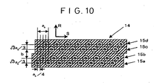
- the second array method will be shown in FIG. 10 .
- the respective light source blocks are arranged such that the array direction of the beam irradiation sources included therein is parallel to the sub-scanning direction.
- the distance b between the blocks B and C is 300 ⁇ m. Since ds is 30 ⁇ m and the magnification of the optical system is 1/3, resolution is 2540 dpi. If the position of the light source block A (15a) is used as reference, the light source block B (15b) is shifted by 69 ⁇ m in the main scanning direction and 60 ⁇ m in the sub-scanning direction.
- the light source block C (15c) is shifted by 369 ⁇ m in the main scanning direction and 30 ⁇ m in the sub-scanning direction.
- the light source block B (15d) is shifted by 438 ⁇ m in the main scanning direction and 90 ⁇ m in the sub-scanning direction.
- the entire imaging area can be imaged without inclining the array in the sub-scanning direction as shown in FIG. 6 .
- the good image area which is required for the optical system, can be reduced to an extent that a size corresponding to one block is sufficiently included, that is, 0.96 mm (distance (120 ⁇ m) between the beam irradiation sources X the number of beam irradiation sources (8)) as compared with the case in which all beam irradiation sources are arranged in a straight line. Therefore, this value is much smaller than the case of 3.84 mm in which all 32 beam irradiation sources are arranged in a straight line.
- the reduction in the manufacturing cost of the optical system and the miniaturization can be realized. Also, the simplification of the electric circuit for controlling the imaging timing to justify the dot position in the main scanning direction and the cost reduction thereof are possible.
- the first alternative operation is that the feed amount of the imaging head in the sub-scanning direction (normally 320 ⁇ m) and software for outputting image data are changed in accordance with the position of the troubled beam irradiation source. This is the same as the operation explained in the fist array method.
- the second alternative operation will be explained as follows. More specifically, as shown in FIG. 11 , the block A (15a) and the beam irradiation source driving device A (13a) are separated from each other. Also, a block B (15b) and a beam irradiation source driving device B (13b) are separated from each other. Then, the software for outputting imaging data of the main control device 11 is changed from one for all four blocks to one for two blocks.
- the light source blocks of the imaging head are inclined by a predetermined angle ⁇ as shown in FIG. 12 and only blocks C and D (15c and 15d) are used. As a result, the imaging speed is reduced to 1/2, but the imaging operation can be continued without stopping the imaging apparatus.
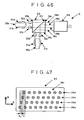
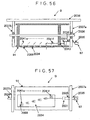
- FIG. 45 One example of the mounting method will be shown in FIG. 45 .
- a fiber array mounting unit 4 has 16 fiber emission ends sandwiched between fiber fixing members 41a and 41b.
- one light source block is formed of eight fiber emission ends in the horizontal direction with respect to paper surface.
- the diameter of a fiber core portion 64a is 50 ⁇ m
- the diameter of a clad portion 65a is 90 ⁇ m.
- the fiber array manufacturing method will be explained as follows. First, eight fiber emission ends are arranged on the valley portions of the fiber fixing member 41a so as to be temporarily fixed. Next, further eight fiber emission ends are arranged to be placed between the temporarily fixed eight fibers. Then, the fiber fixing member 41b is mounted thereon and fixed.
- the fiber array mounting unit 4 in which the light blocks A and B of FIG. 10 are combined is completed.
- the light source blocks C and D can be manufactured in completely the same manner as the light source blocks A and B.
- FIG. 24 shows the first example of the optical fiber array apparatus of the present invention.
- FIG. 25 shows the arrangement of the optical fiber emission ends.
- the optical fiber array apparatus 3001 comprises four optical fiber rows (3011a to 3011d) in which 10 optical fiber emission ends are arranged in a straight line. In each optical fiber row, 10 optical fiber emission ends are arranged in a straight line with a distance of 125 ⁇ m. The respective fiber rows are arranged such that the direction of the optical fiber emission ends included therein is parallel to the sub-scanning direction.
- the optical fiber row 3011b is shifted by 108 ⁇ m in the main scanning direction and 62.5 ⁇ m in the sub-scanning direction.
- the optical fiber row 3011c is shifted by 608 ⁇ m in the main scanning direction and 31.25 ⁇ m in the sub-scanning direction.
- the optical fiber row 3011d is shifted by 716 ⁇ m in the main scanning direction and 93.75 ⁇ m in the sub-scanning direction.
- b is 500 ⁇ m, which is fourfold of the distance of 125 ⁇ m between the optical fiber emission ends.
- the use of the optical fiber array apparatus 3001 and the optical system having a magnification of 0. 32 times makes it possible to execute the imaging with 2540 dpi.
- the number of optical fibers emission ends of one optical fiber row is 10. However, if the number of optical fibers emission ends is two or more, any number is possible.
- the favorable range is 8 to 32.
- the entire imaging area can be imaged without inclining the optical fiber array apparatus as shown in FIG. 6 .
- the good image area which is required for the optical system, can be reduced to an extent (i. e. , about 1. 4 mm) that the length of one optical fiber row is sufficiently included as compared with the case in which all optical fiber emission ends are arranged in a straight line and the case in which the optical fiber emission ends are arranged in two rows. Therefore, a large amount of optical fiber emission ends can be arranged without increasing the cost of the optical system and the size thereof.
- the shift amount of the optical fiber emission ends in the main scanning direction can be reduced to about 716 ⁇ m, that is, less than six times as large as the distance between the optical fiber emission ends. For this reason, many optical fiber emission ends can be arranged without complicating the electric circuit for controlling timing of imaging with the shift or without increasing the manufacturing cost. In this case, contrivance of the sub-scanning method and the rearrangement of data are not necessarily needed.
- FIGS. 26A to 26E The manufacturing process will be shown in FIGS. 26A to 26E .
- the columnar material 3019 for forming an optical fiber support member is prepared.
- a two-stage fiber fixing groove is formed in upper and lower portions by discharge process etc., so as to manufacture the optical fiber support member 3017.
- the two-stage fiber fixing groove is formed to have a width, that is, 1375 ⁇ m, where 11 optical fibers can be arranged.
- the bottom surface of the fiber fixing groove functions as the parallel portions 3015a and 3015b.
- the side surface functions as restricting portions 3016a to 3016d.
- the parallel portions 3015a and 3015b are precisely processed to be parallel to each other.
- the restricting portions 3016a to 3016d are precisely processed such that the shift of the optical fiber array direction between the restricting portions 3016a and 3016c and the shift of the optical fiber array direction between the restricting portions 3016b and 3016d are set to 93.75 ⁇ m.
- the optical fiber row 3011b having 10 optical fibers and one dummy fiber 3014a whose diameter is equal to the optical fiber serving as the light source are arranged as follows. More specifically, they are arranged in the parallel portion 3015a such that the optical fiber positioned at the left edge is closely in contact with the restricting portion 3016a and the dummy fiber 3014a is closely in contact with the restricting portion 3016b. Moreover, the optical fiber row 3011a having 10 optical fibers is arranged on these optical fibers in a barrel-piling manner.
- the pressing member 3013a is pressed thereon, and upper and lower portions are inverted as shown in FIG. 26D . Thereafter, the optical fiber row 3011c having 10 optical fibers and one dummy fiber 3014b are arranged, and the optical fiber row 3011d having 10 optical fibers is arranged thereon in the same manner as shown in FIG. 26C . Finally, as shown in FIG. 26E , the pressing member 3013b is pressed thereon, and the space is filled with adhesive to be hardened so that the above members are combined into one. The optical fiber array apparatus is thus completed.
- FIG. 27 The second example of the optical fiber array apparatus of the present invention is shown in FIG. 27 .
- the array of the optical fiber emission ends is shown in FIG. 28 .
- the optical fiber array apparatus 3001 comprises two optical fiber rows (3011a and 3011b) in which 20 optical fiber emission ends are arranged in a straight line. In each optical fiber row, 20 optical fiber emission ends are arranged in a straight line with a distance of 125 ⁇ m.
- the array direction of the optical fiber emission ends included in each optical fiber row is provided to have a predetermined angle ⁇ with respect to the sub-scanning direction.
- the angle ⁇ is defined as in equation (1). In this case, since the distance a s between the optical fiber emission ends is 125 ⁇ m and the dot distance d s between the light source surfaces is 31.25 ⁇ m, the angle ⁇ is 75.5°.
- the optical fiber 3011b is shifted by 0 in the main direction and 625 ⁇ m in the sub-scanning direction.
- the use of the optical fiber array apparatus and the optical system having a magnification of 0. 32 times makes it possible to execute the imaging with 2540 dpi.
- the number of optical fibers emission ends of one optical fiber row is 20. However, if the number of optical fibers emission ends is two or more, any number is possible.
- the favorable range is 8 to 32.
- the good image area, which is required for the optical system can be reduced to an extent (i.e., about 2.9 mm) that the length of one optical fiber row is sufficiently included as compared with the case in which all optical fiber emission ends are arranged in a straight. Therefore, a large amount of optical fiber emission ends can be arranged without increasing the cost of the optical system and the size thereof.
- the shift amount of the optical fiber emission ends in the main scanning direction can be reduced to a half, many optical fiber emission ends can be arranged without complicating the electric circuit for controlling timing of imaging with the shift or without increasing the manufacturing cost.
- the method for manufacturing the optical fiber array apparatus with a good positional accuracy of the optical fiber emission ends is basically the same as the manufacturing process shown in the optical fiber array of the first example.
- the difference therebetween is the formation of only one optical fiber row in one fiber fixing groove and the positional relationship between the parallel portions and the restricting portions.
- the fiber fixing groove has a width, that is, 2500 ⁇ m, where 20 optical fibers can arranged.
- the distance between the parallel portions is precisely processed to be 480 ⁇ m and the shift between the restricting portions is also precisely processed to be 156 ⁇ m.
- FIG. 29 The third example of the optical fiber array apparatus of the present invention is shown in FIG. 29 .
- the arrangement of the optical fiber emission ends of the fiber array apparatus is shown in FIG. 30 .
- the optical fiber array apparatus 3001 comprises six optical fiber rows (3011a and 3011f) in which 10 optical fiber emission ends are arranged in a straight line. In each optical fiber row, 10 optical fiber emission ends are arranged in a straight line with a distance of 120 ⁇ m. The array direction of the optical fiber emission ends included in each optical fiber row is formed to be parallel to the sub-scanning direction.
- the optical fiber row 3011b is shifted by 104 ⁇ m in the main scanning direction and 60 ⁇ m in the sub-scanning direction.
- the optical fiber row 3011c is shifted by 284 ⁇ m in the main scanning direction and 20 ⁇ m in the sub-scanning direction.
- the optical fiber row 3011d is shifted by 388 ⁇ m in the main scanning direction and 80 ⁇ m in the sub-scanning direction.
- the optical fiber row 3011e is shifted by 568 ⁇ m in the main scanning direction and 40 ⁇ m in the sub-scanning direction.
- the optical fiber row 3011f is shifted by 672 ⁇ m in the main scanning direction and 100 ⁇ m in the sub-scanning direction.
- b is 180 ⁇ m, which is 1.5 times as large as the distance between the optical fiber emission ends of 120 ⁇ m.
- the use of the optical fiber array apparatus and the optical system having a magnification of 0. 5 times makes it possible to execute the imaging with 2540 dpi.
- the number n of optical fibers emission ends of one optical fiber row is 10. However, if the number of optical fibers emission ends is two or more, any number is possible.
- the favorable range is 8 to 32.
- the entire imaging area can be imaged without inclining the optical fiber array apparatus as shown in FIG. 6 .
- the good image area which is required for the optical system, can be reduced to an extent (i.e., about 1. 1 mm) that the length of one optical fiber row is sufficiently included as compared with the case in which all optical fiber emission ends are arranged in a straight line and the case in which the optical fiber emission ends are arranged in two rows. Therefore, a large amount of optical fiber emission ends can be arranged without increasing the cost of the optical system and the size thereof.
- the shift amount of the optical fiber emission ends in the main scanning direction can be reduced to about 672 ⁇ m, that is, less than six times as large as the distance between the optical fiber emission ends. For this reason, many optical fiber emission ends can be arranged without complicating the electric circuit for controlling timing of imaging with the shift or without increasing the manufacturing cost. In this case, contrivance of the sub-scanning method and the rearrangement of data are not necessarily needed.
- FIGS. 31A to 31E The manufacturing process will be shown in FIGS. 31A to 31E .
- the columnar material 3019 for forming an optical fiber support member is prepared.
- the two-stage groove is formed by wire discharge process etc., so as to manufacture an optical fiber support member 3017a.
- the two-stage groove is formed such that a bottom portion has a width, i.e., 1320 ⁇ m where 11 optical fibers can be arranged and an opening portion has a width, i.e. , 1720 ⁇ m equal to the widths of optical fiber arranging members 3017b and 3017c.
- the optical fiber arranging members 3017b and 3017c have fiber fixing grooves each having a width where 11 optical fibers can be arranged.
- the optical fiber support member 3017a and the optical fiber arranging members 3017b and 3017c are combined into one as described later, and function as an optical fiber support member.
- the bottom surface of the groove of the support member 3017a functions as the parallel portion 3015a
- the bottom surfaces of the fiber fixing grooves of the arranging member 3017b and 3017c function as the parallel portions 3015b and 3015c.
- the side surface of the groove of the support member 3017a functions as restricting portions 3016a and 3016b
- the side surfaces of the grooves of the optical fiber arranging members 3017b and 3017c function as restricting portions 3016c to 3016f. For this reason, the parallel portions 3015a and 3015c are precisely processed to be parallel to each other.
- restriction portions 3016a to 3016f are precisely processed such that the shift of the optical fiber array direction between the restricting portions 3016a, 3016c, 3016e and the restricting portions 3016b, 3016d, 3016f is a pitch of 20 ⁇ m.
- the optical fiber row 3011a having 10 optical fibers and one dummy fiber 3014a whose diameter is equal to the optical fiber serving as the light source are arranged as follows. More specifically, they are arranged in the parallel portion 3015a such that the optical fiber positioned at the left edge is closely in contact with the restricting portion 3016a and the dummy fiber 3014a is closely in contact with the restricting portion 3016b. Moreover, the optical fiber row 3011b having 10 optical fibers is arranged on these optical fibers in a barrel-piling manner.
- the optical fiber arranging member 3017b is pressed thereon.
- the optical fiber row 3011c having 10 optical fibers and one dummy fiber 3014b whose diameter is equal to the optical fiber serving as the light source are arranged in the parallel portion 3015b. In this case, they are arranged such that the optical fiber positioned at the left edge is closely in contact with the restricting portion 3016c and the dummy fiber 3014b is closely in contact with the restricting portion 3016d.
- the optical fiber row 3011d having 10 optical fibers is arranged on these optical fibers in a barrel-piling manner.
- the optical fiber arranging member 3017c, the optical fiber row 3011e having 10 optical fibers and one dummy fiber 3014c are arranged, and the optical fiber row 3011f having 10 optical fibers is arranged thereon in the same manner as shown in FIG. 31D .
- the pressing member 3013 is pressed thereon, and the space is filled with adhesive to be hardened so that the above members are combined into one. The optical fiber array apparatus is thus completed.
- FIG. 32 The fourth example of the optical fiber array apparatus of the present invention is shown in FIG. 32 .
- the array of the optical fiber emission ends is shown in FIG. 33 .
- the optical fiber array apparatus 3001 comprises four optical fiber rows (3011a and 3011d) in which 10 optical fiber emission ends are arranged in a straight line.
- each optical fiber row 10 optical fiber emission ends are arranged in a straight line with a distance of 125 ⁇ m.
- the array direction of the optical fiber emission ends included in each optical fiber row is formed to be parallel to the sub-scanning direction. If the position of the optical fiber row 3011a is used as a reference, the optical fiber row 3011b is shifted by 175 ⁇ m in the main scanning direction and 62.5 ⁇ m in the sub-scanning direction.
- the optical fiber row 3011c is shifted by 675 ⁇ m in the main scanning direction and 31.25 ⁇ m in the sub-scanning direction.
- the optical fiber row 3011d is shifted by 850 ⁇ m in the main scanning direction and 93.75 ⁇ m in the sub-scanning direction.
- b is 500 ⁇ m, which is four times as large as the distance between the fiber emission ends
- c is a sum, i.e., 175 ⁇ m of the clad diameter, 125 ⁇ m, of the fibers and the thickness, 50 ⁇ m, of the spacers.
- the number n of optical fibers emission ends of one optical fiber row is 10.
- the number of optical fibers emission ends is two or more, any number is possible.
- the favorable range is 8 to 32.
- the entire imaging area can be imaged without inclining the optical fiber array apparatus as shown in FIG. 6 .
- the good image area, which is required for the optical system can be reduced to an extent (about 1. 4 mm) that the length of one optical fiber row is sufficiently included as compared with the case in which all optical fiber emission ends are arranged in a straight line and the case in which the optical fiber emission ends are arranged in two rows. Therefore, a large amount of optical fiber emission ends can be arranged without increasing the cost of the optical system and the size thereof.
- the shift amount of the optical fiber emission ends in the main scanning direction can be reduced to about 850 ⁇ m, that is, less than 8 times as large as the distance between the optical fiber emission ends. For this reason, many optical fiber emission ends can be arranged without complicating the electric circuit for controlling timing of imaging with the shift or without increasing the manufacturing cost. In this case, contrivance of the sub-scanning method and the rearrangement of data are not necessarily needed.
- FIGS. 34A to 34E The manufacturing process will be shown in FIGS. 34A to 34E .
- the columnar material 3019 for forming an optical fiber support member is prepared.
- a two-stage fiber fixing groove is formed in upper and lower portions by wire discharge process etc., so as to manufacture an optical fiber support member 3017.
- a width of the first-stage of the two-stage fiber fixing groove is such that 10 optical fibers can be arranged, and a width of the second-stage thereof is such that 11 optical fibers can be arranged.
- the bottom surface of the fiber fixing groove functions as the parallel portions 3015a and 3015b.
- the first-stage side surfaces 3016a, 3016b, 3016e, 3016f and the second-stage side surfaces 3016c, 3016d, 3016g, 3016h function as restricting portions.
- the parallel portions 3015a and 3015c are precisely processed to be parallel to each other.
- the restricting portions 3016a to 3016h are precisely processed such that the shift of the optical fiber array direction among the restricting portions 3016a, 3016c, the restricting portions 3016b, 3016d, the restricting portions 3016e and 3016g, and the restricting portions 3016f and 3016h are set to 62. 5 ⁇ m and that the shift of the optical fiber array direction between the restricting portions 3016a, 3016e and the restricting portions 3016b, 3016f is set to 31.25 ⁇ m.
- the optical fiber row 3011b having 10 optical fibers is arranged in the parallel portion 3015a such that the optical fiber left end positioned at the left edge is closely in contact with the restricting portion 3016a and the optical fiber positioned at the right edge is closely in contact with the restricting portion 3016b.
- a spacer 3018a is mounted on these optical fibers, and the optical fiber row 3011a having 10 optical fibers and one dummy fiber 3014a whose diameter is equal to the optical fiber serving as the light source are arranged thereon. More specifically, they are arranged such that the left edge of the dummy fiber 3014a is closely in contact with the restricting portion 3016c and the optical fiber positioned at the right edge is closely in contact with the restricting portion 3016d.
- the pressing member 3013a is pressed thereon, and upper and lower portions are inverted as shown in FIG. 34D . Thereafter, the optical fiber row 3011c having 10 optical fibers, the spacer 3018b are arranged, and the optical fiber row 3011d having 10 optical fibers and one dummy fiber 3014b are arranged thereon in the same manner as shown in FIG. 34C . Finally, as shown in FIG. 34E , the pressing member 3013b is pressed thereon, and the space is filled with adhesive to be hardened so that the above members are combined into one.
- the fifth example of the optical fiber array apparatus of the present invention is shown in FIG. 35 .
- the array of the optical fiber emission ends is shown in FIG. 36 .
- the optical fiber array apparatus 3001 comprises 10 optical fiber rows (3011a and 3011j) in which four optical fiber emission ends are arranged in a straight line. In each optical fiber row, four optical fiber emission ends are arranged in a straight line to have a distance and an angle such that the projection in the sub-scanning direction becomes 50 ⁇ m. If the position of the optical fiber row 3011a is used as a reference, the optical fiber row 3011b is shifted by 200 ⁇ m in the sub-scanning direction. The optical fiber row 3011c is shifted by 400 ⁇ m in the sub-scanning direction. The optical fiber row 3011d is shifted by 600 ⁇ m ..., and the optical fiber row 3011j is shifted by 1800 ⁇ m in the sub-scanning direction.
- the use of the optical fiber array apparatus and the optical system having a magnification of 0. 20 times makes it possible to execute the imaging with 2540 dpi.
- the number n of optical fibers emission ends of one optical fiber row is four.
- two to eight optical fiber emission ends are practically used, and the most favorable number of optical fiber emission ends is four.
- the entire imaging area can be imaged without inclining the optical fiber array apparatus as shown in FIG. 6 .
- the good image area which is required for the optical system, can be reduced to an extent that the clad diameter is about twice as many as the number of optical fiber rows.
- the good image area can be reduced to 2. 5 mm. Therefore, a large amount of optical fiber emission ends can be arranged without increasing the cost of the optical system and the size thereof.
- the shift amount of the optical fiber emission ends in the main scanning direction can be reduced to be below three times as large as the clad diameter of the fiber, that is, 375 ⁇ m. For this reason, many optical fiber emission ends can be arranged without complicating the electric circuit for controlling timing of imaging with the shift or without increasing the manufacturing cost. In this case, contrivance of the sub-scanning method and the rearrangement of data are not necessarily needed.
- FIG. 37 shows an enlarged view of the fiber support portion of a comblike optical fiber support member 3027, which makes it possible to manufacture the optical fiber array apparatus with a good accuracy of the optical fiber emission ends.
- comblike grooves are formed in the fiber support portion of the comblike optical fiber support member 3027. More specifically, the comblike grooves are formed by wire discharge process so as to have a width where one optical fiber can arranged, that is, 127 ⁇ m corresponding to the number of fiber emission ends of one fiber row, and a depth corresponding to four fiber emission ends. In other words, the comblike grooves of 500 ⁇ m, which corresponds to the number of fiber rows, are formed.
- the bottom surface of the fiber fixing groove functions as the restricting portions 3016a, 3016b, 3016c, ..., 3016j.
- the side surface functions as parallel portions 3015a, 3015b, 3015c, ..., 3015t.
- the parallel portions 3015a, 3015b, 3015c, ..., 3015t are precisely processed so as to be all parallel to each other.
- the restricting portions 3016a to 3016j are precisely processed such that the shift in the main scanning direction becomes 0, and that the distance between the adjacent restricting portions in the sub-scanning direction becomes 200 ⁇ m, and that the width of the groove ranges 1.012 to 1.020 times as large as the optical fiber diameter of 125 ⁇ m, that is, 126.5 to 127.5 ⁇ m.
- the actual manufacturing method is as follows. More specifically, 40 fibers are closely arranged at the fiber support portion of the comblike fiber support member 3027, and the pressing member 3013 is pressed thereon. Then, the space is filled with adhesive to be hardened so that the above members are combined into one, thereby the manufacture of the comblike fiber support member can be realized.
- the optical fiber support member having the positioning portions such as the parallel portions and the restricting portions is used, thereby making possible to provide the multi-stage piling optical fiber array apparatus having a good positional accuracy.
Landscapes
- Physics & Mathematics (AREA)
- Optics & Photonics (AREA)
- General Physics & Mathematics (AREA)
- Health & Medical Sciences (AREA)
- General Health & Medical Sciences (AREA)
- Toxicology (AREA)
- Printers Or Recording Devices Using Electromagnetic And Radiation Means (AREA)
- Exposure And Positioning Against Photoresist Photosensitive Materials (AREA)
- Laser Beam Printer (AREA)
- Electronic Switches (AREA)
- Facsimile Scanning Arrangements (AREA)
- Facsimile Heads (AREA)
Claims (5)
- Optische Faserarray-Vorrichtung (3001) umfassend eine Mehrzahl von optischen Faser-Doppelreihen (3011a, 3011b, 3011c, 3011d), die eine erste optische Faserreihe (3011c, 3011d; 3011a, 3011c, 3011e) mit Emissionsenden von optischen Fasern, die in einer Reihe mit einem vorgegebenen Abstand zueinander angeordnet sind, und eine zweite optische Faserreihe (3011d, 3011a) aufweisen, die die erste optische Faserreihe eng kontaktiert und Emissionsenden von optischen Fasern aufweist, die in einer Reihe mit einem vorgegebenen Abstand zueinander angeordnet sind, wobei die zweite optische Faserreihe an einer Position angeordnet ist, die um 0,5 mal der Breite des vorgegebenen Abstands in der Anordnungsrichtung von der ersten optischen Faserreihe verschoben ist; und
ein optisches Faser-Abstützelement (3017) zum Abstützen der optischen Faser-Doppelreihen, wobei das optische Faser-Abstützelement aufweist:parallele Bereiche (3015a, 3015b), die die ersten optischen Faserreihen (3011c, 3011b) längs der ersten optischen Faserreihen eng kontaktieren, dadurch gekennzeichnet, dass das optische Faser-Abstützelement (3017) fernerBegrenzungsbereiche (3016a - h) zur Begrenzung einer Bewegung der optischen Faser-Doppelreihen in ihrer Anordnungsrichtung aufweist, um die optischen Fasern so zu positionieren, dass eine Distanz zwischen optischen Achsen der optischen Fasern am Rand von jeder der optischen Faserreihen in einer Überstandsrichtung, die einen vorgegebenen Winkel zur Anordnungsrichtung bilden, einen Wert von 1/4 bis 1/6 des vorgegebenen Abstands annimmt. - Optische Faserarray-Vorrichtung nach Anspruch 1, wobei zwei oder mehr parallele Bereiche (3015a - c) am optischen Faser-Abstützelement (3017) vorgesehen sind und die Begrenzungsbereiche (3016a - h) an zumindest einem Rand von jeden der parallelen Bereiche (3015a, 3015b) vorgesehen sind.
- Optische Faserarray-Vorrichtung nach Anspruch 1 oder 2, wobei das optische Faser-Abstützelement (3017) eine oder mehrere optische Faser-Anordnungselemente (3017b - c), Abstützelemente für die Anordnungselemente, zumindest einen parallelen Bereich (3015c - f) und zumindest einen Begrenzungsbereich (3016c - f) aufweist, die an den optischen Faser-Anordnungselementen (3017b - c) vorgesehen sind.
- Bildgebende Kopfvorrichtung, die die in einem der Ansprüche 1 bis 3 beschriebene optische Faserarray-Vorrichtung (3001) und Laser-Emissionsenden, die jeder der optischen Fasen in der optischen Faserarray-Vorrichtung Licht zuführt, und ein optisches System zum Kondensieren von Laserstrahlen aufweist, die von der optischen Faserarray-Vorrichtung emittiert wurden.
- Bildgebende Vorrichtung zur Ausführung einer Bildgebung durch die in Anspruch 4 beschriebene bildgebende Kopfvorrichtung.
Applications Claiming Priority (5)
| Application Number | Priority Date | Filing Date | Title |
|---|---|---|---|
| JP7410197 | 1997-03-26 | ||
| JP7410197 | 1997-03-26 | ||
| JP19149297 | 1997-07-16 | ||
| JP19149297 | 1997-07-16 | ||
| EP98909850A EP0945276B1 (de) | 1997-03-26 | 1998-03-24 | Bilderzeugungsvorrichtung,-verfahren und druckvorrichtung |
Related Parent Applications (2)
| Application Number | Title | Priority Date | Filing Date |
|---|---|---|---|
| EP98909850A Division EP0945276B1 (de) | 1997-03-26 | 1998-03-24 | Bilderzeugungsvorrichtung,-verfahren und druckvorrichtung |
| EP98909850.4 Division | 1998-10-01 |
Publications (3)
| Publication Number | Publication Date |
|---|---|
| EP1552943A2 EP1552943A2 (de) | 2005-07-13 |
| EP1552943A3 EP1552943A3 (de) | 2005-07-20 |
| EP1552943B1 true EP1552943B1 (de) | 2012-06-06 |
Family
ID=26415242
Family Applications (2)
| Application Number | Title | Priority Date | Filing Date |
|---|---|---|---|
| EP05008219A Expired - Lifetime EP1552943B1 (de) | 1997-03-26 | 1998-03-24 | Bilderzeugungsvorrichtung, -verfahren und Druckvorrichtung |
| EP98909850A Expired - Lifetime EP0945276B1 (de) | 1997-03-26 | 1998-03-24 | Bilderzeugungsvorrichtung,-verfahren und druckvorrichtung |
Family Applications After (1)
| Application Number | Title | Priority Date | Filing Date |
|---|---|---|---|
| EP98909850A Expired - Lifetime EP0945276B1 (de) | 1997-03-26 | 1998-03-24 | Bilderzeugungsvorrichtung,-verfahren und druckvorrichtung |
Country Status (7)
| Country | Link |
|---|---|
| US (2) | US6522350B2 (de) |
| EP (2) | EP1552943B1 (de) |
| CN (2) | CN101032879B (de) |
| AU (1) | AU6422698A (de) |
| CA (1) | CA2256446C (de) |
| DE (1) | DE69830894T2 (de) |
| WO (1) | WO1998042516A1 (de) |
Families Citing this family (41)
| Publication number | Priority date | Publication date | Assignee | Title |
|---|---|---|---|---|
| JP3552197B2 (ja) * | 1998-11-06 | 2004-08-11 | 大日本スクリーン製造株式会社 | 画像記録装置 |
| US6148134A (en) * | 1999-03-25 | 2000-11-14 | Schoonscan, Inc. | Fiber mounts for fiber optic harness in a fiber optic-based imaging system |
| JP3150130B2 (ja) * | 1999-03-26 | 2001-03-26 | 新潟日本電気株式会社 | 画像形成装置及びプログラムを記憶した記憶媒体 |
| KR100396192B1 (ko) * | 2000-03-17 | 2003-08-27 | 히타치 프린팅 솔루션즈 가부시키가이샤 | 광주사장치 |
| JP4233196B2 (ja) * | 2000-06-14 | 2009-03-04 | 富士フイルム株式会社 | 露光装置 |
| US6760516B2 (en) * | 2000-06-22 | 2004-07-06 | Avanex Corporation | Multiple -port optical package and DWDM module |
| US20020149665A1 (en) * | 2000-07-03 | 2002-10-17 | Serge Steinblatt | Redundancy for individually addresable laser diode arrays based systems |
| DE10045168B4 (de) * | 2000-09-13 | 2008-07-31 | Hell Gravure Systems Gmbh & Co. Kg | Mehrstrahl-Belichtungsverfahren |
| JP2002169113A (ja) * | 2000-12-01 | 2002-06-14 | Fuji Photo Film Co Ltd | マルチビーム露光ヘッドおよびマルチビーム露光装置 |
| JP2002351086A (ja) | 2001-03-22 | 2002-12-04 | Fuji Photo Film Co Ltd | 露光装置 |
| JP3808327B2 (ja) | 2001-06-13 | 2006-08-09 | 大日本スクリーン製造株式会社 | 画像記録装置 |
| US6778204B2 (en) * | 2001-09-26 | 2004-08-17 | Fuji Photo Film Co., Ltd. | Image recording device |
| US20030147590A1 (en) * | 2002-02-04 | 2003-08-07 | Michael Hahn | Low back reflection two-dimensional fiber array |
| US7436422B2 (en) * | 2003-09-12 | 2008-10-14 | Dainippon Screen Mfg. Co., Ltd. | Light source module, optical unit array and pattern writing apparatus |
| US20050104953A1 (en) * | 2003-09-16 | 2005-05-19 | Fuji Photo Film Co., Ltd. | Image exposure method and image exposure apparatus |
| JP4311216B2 (ja) * | 2004-02-02 | 2009-08-12 | コニカミノルタホールディングス株式会社 | インクジェット記録装置 |
| JP4508743B2 (ja) * | 2004-03-31 | 2010-07-21 | 日立ビアメカニクス株式会社 | パターン露光方法およびパターン露光装置 |
| US7661807B2 (en) * | 2004-07-21 | 2010-02-16 | Seiko Epson Corporation | Ultraviolet rays emitter |
| JP4777759B2 (ja) * | 2005-12-01 | 2011-09-21 | 富士フイルム株式会社 | 配線基板及び配線基板接続装置 |
| DE102006059818B4 (de) * | 2006-12-11 | 2017-09-14 | Kleo Ag | Belichtungsanlage |
| US20100156761A1 (en) * | 2008-12-19 | 2010-06-24 | Janos Veres | Edge emissive display device |
| DE102009032210B4 (de) | 2009-07-03 | 2011-06-09 | Kleo Ag | Bearbeitungsanlage |
| US8424348B2 (en) * | 2010-01-27 | 2013-04-23 | Strattec Security Corporation | Steering lock |
| EP2545356B1 (de) * | 2010-03-09 | 2015-12-02 | Beckman Coulter, Inc. | Berechnete tropfverzögerung für flusszytometriesysteme und verfahren dafür |
| JP5536711B2 (ja) * | 2011-05-16 | 2014-07-02 | パナソニック株式会社 | 画像記録装置 |
| US20140153880A1 (en) * | 2012-11-30 | 2014-06-05 | General Electric Company | Device and method for bundling optical fibers |
| JP6003934B2 (ja) * | 2014-03-20 | 2016-10-05 | トヨタ自動車株式会社 | レーザー溶接検査装置及びレーザー溶接検査方法 |
| EP3202580B1 (de) * | 2016-02-05 | 2019-09-25 | Ricoh Company, Ltd. | Aufzeichnungsverfahren |
| WO2017135460A1 (ja) * | 2016-02-05 | 2017-08-10 | 株式会社リコー | 画像記録装置および画像記録方法 |
| EP3412468B1 (de) * | 2016-02-05 | 2020-04-08 | Ricoh Company, Ltd. | Bildaufzeichnungsvorrichtung und bildaufzeichnungsverfahren |
| WO2017135328A1 (ja) * | 2016-02-05 | 2017-08-10 | 株式会社リコー | 画像記録装置および画像記録方法 |
| JP6891816B2 (ja) | 2016-02-05 | 2021-06-18 | 株式会社リコー | 記録方法及び記録装置 |
| WO2017135459A1 (ja) | 2016-02-05 | 2017-08-10 | 株式会社リコー | 画像記録装置および画像記録方法 |
| CN108602354B (zh) * | 2016-02-05 | 2020-01-10 | 株式会社理光 | 图像记录设备和图像记录方法 |
| EP3412464B1 (de) * | 2016-02-05 | 2020-03-04 | Ricoh Company, Ltd. | Aufzeichnungsverfahren und aufzeichnungsvorrichtung |
| US11710942B2 (en) * | 2017-12-13 | 2023-07-25 | Sony Corporation | Method of manufacturing light-emitting module, light-emitting module, and device |
| CN109927394B (zh) * | 2017-12-16 | 2021-07-20 | 绍兴豪春纺织科技有限公司 | 一种蓝光制网机 |
| TWI843720B (zh) * | 2018-03-13 | 2024-06-01 | 小池康 | 一體成型多重光傳送片、一體成型多重光傳送片連接器及其製造方法 |
| CN108897095B (zh) * | 2018-08-03 | 2023-05-26 | 华侨大学 | 一种定向背光源裸眼3d平行光纤阵列制作装置 |
| CN110376689B (zh) * | 2019-07-22 | 2021-02-12 | 上海营湾医疗科技有限公司 | 光电耦合透镜组 |
| US11640031B2 (en) * | 2020-05-27 | 2023-05-02 | Corning Research & Development Corporation | Laser-cleaving of an optical fiber array with controlled cleaving angle |
Family Cites Families (27)
| Publication number | Priority date | Publication date | Assignee | Title |
|---|---|---|---|---|
| US3832488A (en) * | 1972-06-29 | 1974-08-27 | Singer Co | Non-impact printer |
| JPS5630156A (en) * | 1979-08-21 | 1981-03-26 | Oki Electric Ind Co Ltd | Photoprint head |
| JPS56150550A (en) | 1980-04-23 | 1981-11-21 | Toray Ind Inc | Planographic printer |
| US4351226A (en) | 1980-05-27 | 1982-09-28 | Parker-Hannifin Corporation | Fluid control system |
| JPS57188003A (en) * | 1981-05-15 | 1982-11-18 | Ricoh Co Ltd | Optical fiber array for recorder |
| US4455578A (en) * | 1982-08-30 | 1984-06-19 | Eastman Kodak Company | Electronics for arrayed photosources |
| US4689694A (en) * | 1983-01-12 | 1987-08-25 | Canon Kabushiki Kaisha | Image recording apparatus utilizing linearly arranged recording elements |
| EP0115088B1 (de) * | 1983-01-21 | 1986-12-30 | Agfa-Gevaert N.V. | Aufzeichnungsgerät |
| JPS6044374A (ja) * | 1983-08-19 | 1985-03-09 | Ricoh Co Ltd | プリンタ |
| US4602262A (en) * | 1983-10-13 | 1986-07-22 | Helene Holding Company | Printing apparatus with shifting of head or drum to improve resolution |
| DE3643886A1 (de) * | 1986-03-11 | 1987-09-17 | Kabelmetal Electro Gmbh | Nachrichtenkabel mit lichtwellenleitern |
| US4962464A (en) * | 1987-02-24 | 1990-10-09 | Lavenir Technology, Inc. | Serpentine columnar plotting system |
| US5600363A (en) * | 1988-12-28 | 1997-02-04 | Kyocera Corporation | Image forming apparatus having driving means at each end of array and power feeding substrate outside head housing |
| JPH0452153A (ja) * | 1990-06-20 | 1992-02-20 | Fujitsu Ltd | 解像度可変プリンタ |
| US5124720A (en) * | 1990-08-01 | 1992-06-23 | Hewlett-Packard Company | Fault-tolerant dot-matrix printing |
| US5062115A (en) * | 1990-12-28 | 1991-10-29 | Xerox Corporation | High density, independently addressable, surface emitting semiconductor laser/light emitting diode arrays |
| US5196866A (en) * | 1991-03-15 | 1993-03-23 | Eastman Kodak Company | Focus fiber mount |
| JPH0516320A (ja) | 1991-07-09 | 1993-01-26 | Sony Corp | 半導体レーザ製版装置 |
| JP2744698B2 (ja) * | 1991-11-05 | 1998-04-28 | 三菱電機株式会社 | 陰極線管 |
| US5754218A (en) * | 1992-06-03 | 1998-05-19 | Eastman Kodak Company | Variable dot density printing system using sub-microdot matrixing and a zoom lens |
| US5351617A (en) | 1992-07-20 | 1994-10-04 | Presstek, Inc. | Method for laser-discharge imaging a printing plate |
| US5339737B1 (en) | 1992-07-20 | 1997-06-10 | Presstek Inc | Lithographic printing plates for use with laser-discharge imaging apparatus |
| JPH0647954A (ja) * | 1992-07-29 | 1994-02-22 | Dainippon Screen Mfg Co Ltd | 光源ユニット |
| JPH0730207A (ja) * | 1993-07-09 | 1995-01-31 | Mitsubishi Electric Corp | 半導体レーザアレイモジュールとその組立て方法 |
| JP2766167B2 (ja) * | 1993-08-25 | 1998-06-18 | ソニー株式会社 | レーザ製版装置 |
| US5585836A (en) * | 1993-12-27 | 1996-12-17 | Eastman Kodak Company | Electrophotographic image recording apparatus and method with correction for bow in placement of recording elements |
| KR0132366B1 (ko) * | 1994-11-17 | 1998-04-11 | 김광호 | 레이저 프린트 장치 및 방법 |
-
1998
- 1998-03-24 EP EP05008219A patent/EP1552943B1/de not_active Expired - Lifetime
- 1998-03-24 US US09/194,362 patent/US6522350B2/en not_active Expired - Fee Related
- 1998-03-24 WO PCT/JP1998/001282 patent/WO1998042516A1/ja not_active Ceased
- 1998-03-24 DE DE69830894T patent/DE69830894T2/de not_active Expired - Lifetime
- 1998-03-24 EP EP98909850A patent/EP0945276B1/de not_active Expired - Lifetime
- 1998-03-24 CN CN2007100917190A patent/CN101032879B/zh not_active Expired - Fee Related
- 1998-03-24 CA CA002256446A patent/CA2256446C/en not_active Expired - Fee Related
- 1998-03-24 CN CNB988003635A patent/CN1318222C/zh not_active Expired - Fee Related
- 1998-03-24 AU AU64226/98A patent/AU6422698A/en not_active Abandoned
-
2002
- 2002-12-27 US US10/329,925 patent/US6670979B2/en not_active Expired - Fee Related
Also Published As
| Publication number | Publication date |
|---|---|
| CN1220632A (zh) | 1999-06-23 |
| CA2256446A1 (en) | 1998-10-01 |
| DE69830894T2 (de) | 2006-04-06 |
| US20020015088A1 (en) | 2002-02-07 |
| EP1552943A2 (de) | 2005-07-13 |
| US6522350B2 (en) | 2003-02-18 |
| WO1998042516A1 (fr) | 1998-10-01 |
| EP1552943A3 (de) | 2005-07-20 |
| CA2256446C (en) | 2007-05-29 |
| CN101032879A (zh) | 2007-09-12 |
| EP0945276A1 (de) | 1999-09-29 |
| AU6422698A (en) | 1998-10-20 |
| US6670979B2 (en) | 2003-12-30 |
| CN101032879B (zh) | 2011-12-14 |
| US20030142194A1 (en) | 2003-07-31 |
| EP0945276A4 (de) | 2003-08-06 |
| DE69830894D1 (de) | 2005-08-25 |
| EP0945276B1 (de) | 2005-07-20 |
| CN1318222C (zh) | 2007-05-30 |
Similar Documents
| Publication | Publication Date | Title |
|---|---|---|
| EP1552943B1 (de) | Bilderzeugungsvorrichtung, -verfahren und Druckvorrichtung | |
| GB2413393A (en) | Pattern exposure method and apparatus | |
| EP1275987B1 (de) | Polarisationskontrollelement und Belichtungsvorrichtung | |
| KR100385043B1 (ko) | 다중 빔, 다이오드 펌핑 화상 형성 장치 | |
| EP2759880B1 (de) | Optischer aufzeichnungskopf und bilderzeugungsvorrichtung | |
| JPH10324021A (ja) | イメージング装置およびイメージング方法ならびに印刷装置 | |
| JP4025097B2 (ja) | 露光装置 | |
| US6928198B2 (en) | Exposure head | |
| US6573924B2 (en) | Exposure head and image recording apparatus | |
| JPH1184149A (ja) | 光ファイバアレイ装置、イメージングヘッド装置およびイメージング装置 | |
| EP1376194B1 (de) | Anordnung refraktiver optischer Elemente, Anordnung diffraktiver optischer Elemente und Belichtungsvorrichtung | |
| US7196848B2 (en) | Array refracting element and exposure device | |
| JP4327991B2 (ja) | 光導波路アレイを用いた光学装置 | |
| JP4014990B2 (ja) | 光ファイバの接続方法 | |
| Haas et al. | Single-mode fiber printheads and scanline interleaving for high-resolution laser printing | |
| JP2020112646A (ja) | 光源ユニットおよび露光装置 | |
| US6647189B2 (en) | Image forming apparatus having an optical fiber array | |
| JP2003167167A (ja) | マルチビーム発生装置の製造方法 | |
| JPH11271652A (ja) | マルチビームを用いた光記録装置 | |
| JP2004184436A (ja) | アレイ屈折素子、このアレイ屈折素子を備えた露光装置、アレイ屈折素子製造治具及びアレイ屈折素子製造方法 | |
| JP2003262806A (ja) | 露光装置 | |
| JP2004286900A (ja) | 光ファイバアレイ配列部の製造方法及び光記録装置 | |
| JP2002267980A (ja) | 光ファイバアレイ記録装置 |
Legal Events
| Date | Code | Title | Description |
|---|---|---|---|
| PUAI | Public reference made under article 153(3) epc to a published international application that has entered the european phase |
Free format text: ORIGINAL CODE: 0009012 |
|
| PUAL | Search report despatched |
Free format text: ORIGINAL CODE: 0009013 |
|
| 17P | Request for examination filed |
Effective date: 20050414 |
|
| AC | Divisional application: reference to earlier application |
Ref document number: 0945276 Country of ref document: EP Kind code of ref document: P |
|
| AK | Designated contracting states |
Kind code of ref document: A2 Designated state(s): CH DE FR GB LI |
|
| AK | Designated contracting states |
Kind code of ref document: A3 Designated state(s): CH DE FR GB LI |
|
| AKX | Designation fees paid |
Designated state(s): CH DE FR GB LI |
|
| 17Q | First examination report despatched |
Effective date: 20080414 |
|
| REG | Reference to a national code |
Ref country code: DE Ref legal event code: R079 Ref document number: 69842750 Country of ref document: DE Free format text: PREVIOUS MAIN CLASS: B41J0002440000 Ipc: G02B0006040000 |
|
| GRAP | Despatch of communication of intention to grant a patent |
Free format text: ORIGINAL CODE: EPIDOSNIGR1 |
|
| RIC1 | Information provided on ipc code assigned before grant |
Ipc: G02B 6/04 20060101AFI20110916BHEP Ipc: B41J 2/46 20060101ALI20110916BHEP Ipc: G06K 15/12 20060101ALI20110916BHEP Ipc: G02B 6/06 20060101ALI20110916BHEP Ipc: G03F 7/20 20060101ALI20110916BHEP |
|
| GRAS | Grant fee paid |
Free format text: ORIGINAL CODE: EPIDOSNIGR3 |
|
| GRAA | (expected) grant |
Free format text: ORIGINAL CODE: 0009210 |
|
| AC | Divisional application: reference to earlier application |
Ref document number: 0945276 Country of ref document: EP Kind code of ref document: P |
|
| AK | Designated contracting states |
Kind code of ref document: B1 Designated state(s): CH DE FR GB LI |
|
| REG | Reference to a national code |
Ref country code: GB Ref legal event code: FG4D |
|
| REG | Reference to a national code |
Ref country code: CH Ref legal event code: EP |
|
| REG | Reference to a national code |
Ref country code: DE Ref legal event code: R096 Ref document number: 69842750 Country of ref document: DE Effective date: 20120802 |
|
| REG | Reference to a national code |
Ref country code: CH Ref legal event code: NV Representative=s name: KELLER & PARTNER PATENTANWAELTE AG |
|
| PLBE | No opposition filed within time limit |
Free format text: ORIGINAL CODE: 0009261 |
|
| STAA | Information on the status of an ep patent application or granted ep patent |
Free format text: STATUS: NO OPPOSITION FILED WITHIN TIME LIMIT |
|
| PGFP | Annual fee paid to national office [announced via postgrant information from national office to epo] |
Ref country code: FR Payment date: 20130329 Year of fee payment: 16 Ref country code: DE Payment date: 20130328 Year of fee payment: 16 Ref country code: GB Payment date: 20130318 Year of fee payment: 16 Ref country code: CH Payment date: 20130319 Year of fee payment: 16 |
|
| 26N | No opposition filed |
Effective date: 20130307 |
|
| REG | Reference to a national code |
Ref country code: DE Ref legal event code: R097 Ref document number: 69842750 Country of ref document: DE Effective date: 20130307 |
|
| REG | Reference to a national code |
Ref country code: DE Ref legal event code: R119 Ref document number: 69842750 Country of ref document: DE |
|
| REG | Reference to a national code |
Ref country code: CH Ref legal event code: PL |
|
| GBPC | Gb: european patent ceased through non-payment of renewal fee |
Effective date: 20140324 |
|
| REG | Reference to a national code |
Ref country code: FR Ref legal event code: ST Effective date: 20141128 |
|
| REG | Reference to a national code |
Ref country code: DE Ref legal event code: R119 Ref document number: 69842750 Country of ref document: DE Effective date: 20141001 |
|
| PG25 | Lapsed in a contracting state [announced via postgrant information from national office to epo] |
Ref country code: FR Free format text: LAPSE BECAUSE OF NON-PAYMENT OF DUE FEES Effective date: 20140331 Ref country code: DE Free format text: LAPSE BECAUSE OF NON-PAYMENT OF DUE FEES Effective date: 20141001 Ref country code: CH Free format text: LAPSE BECAUSE OF NON-PAYMENT OF DUE FEES Effective date: 20140331 Ref country code: GB Free format text: LAPSE BECAUSE OF NON-PAYMENT OF DUE FEES Effective date: 20140324 Ref country code: LI Free format text: LAPSE BECAUSE OF NON-PAYMENT OF DUE FEES Effective date: 20140331 |