EP1553347B1 - Appareil de menage, en spéciale une cuisinère - Google Patents
Appareil de menage, en spéciale une cuisinère Download PDFInfo
- Publication number
- EP1553347B1 EP1553347B1 EP04002457.2A EP04002457A EP1553347B1 EP 1553347 B1 EP1553347 B1 EP 1553347B1 EP 04002457 A EP04002457 A EP 04002457A EP 1553347 B1 EP1553347 B1 EP 1553347B1
- Authority
- EP
- European Patent Office
- Prior art keywords
- muffle
- household appliance
- mounting part
- appliance according
- mounting
- Prior art date
- Legal status (The legal status is an assumption and is not a legal conclusion. Google has not performed a legal analysis and makes no representation as to the accuracy of the status listed.)
- Expired - Lifetime
Links
- 238000010411 cooking Methods 0.000 title claims description 27
- 238000003780 insertion Methods 0.000 claims description 26
- 230000037431 insertion Effects 0.000 claims description 26
- 229910000831 Steel Inorganic materials 0.000 description 9
- 239000010959 steel Substances 0.000 description 9
- 239000000725 suspension Substances 0.000 description 9
- 238000004519 manufacturing process Methods 0.000 description 7
- 238000005516 engineering process Methods 0.000 description 6
- 230000013011 mating Effects 0.000 description 5
- 210000003298 dental enamel Anatomy 0.000 description 3
- 239000011343 solid material Substances 0.000 description 3
- 238000004049 embossing Methods 0.000 description 2
- 230000004048 modification Effects 0.000 description 2
- 238000012986 modification Methods 0.000 description 2
- 238000005452 bending Methods 0.000 description 1
- 238000011109 contamination Methods 0.000 description 1
- 238000000605 extraction Methods 0.000 description 1
- 230000017525 heat dissipation Effects 0.000 description 1
- 239000011796 hollow space material Substances 0.000 description 1
- 238000009434 installation Methods 0.000 description 1
- 239000000463 material Substances 0.000 description 1
- 239000002184 metal Substances 0.000 description 1
- 230000002093 peripheral effect Effects 0.000 description 1
- 238000009964 serging Methods 0.000 description 1
- 230000008646 thermal stress Effects 0.000 description 1
- 230000007704 transition Effects 0.000 description 1
- 238000011144 upstream manufacturing Methods 0.000 description 1
Images




Classifications
-
- F—MECHANICAL ENGINEERING; LIGHTING; HEATING; WEAPONS; BLASTING
- F24—HEATING; RANGES; VENTILATING
- F24C—DOMESTIC STOVES OR RANGES ; DETAILS OF DOMESTIC STOVES OR RANGES, OF GENERAL APPLICATION
- F24C15/00—Details
- F24C15/16—Shelves, racks or trays inside ovens; Supports therefor
- F24C15/168—Shelves, racks or trays inside ovens; Supports therefor with telescopic rail systems
-
- F—MECHANICAL ENGINEERING; LIGHTING; HEATING; WEAPONS; BLASTING
- F25—REFRIGERATION OR COOLING; COMBINED HEATING AND REFRIGERATION SYSTEMS; HEAT PUMP SYSTEMS; MANUFACTURE OR STORAGE OF ICE; LIQUEFACTION SOLIDIFICATION OF GASES
- F25D—REFRIGERATORS; COLD ROOMS; ICE-BOXES; COOLING OR FREEZING APPARATUS NOT OTHERWISE PROVIDED FOR
- F25D23/00—General constructional features
- F25D23/06—Walls
- F25D23/065—Details
- F25D23/067—Supporting elements
Definitions
- the invention relates to household appliance, in particular cooking appliance with a device muffle, in the muffle wall, a holding element is provided for suspending a Ein mentalteils.
- the DE 195 00 371 A1 describes a baking oven muffle in the side walls guide rails are mounted. On one of the guide grid, a pivotable latch is articulated, which can be brought into locking engagement with the opposite guide grid.
- Telescopic guides can be stored on the side walls of a baking oven muffle.
- Each telescopic guide has an outer rail on which a hook is formed for hanging in an opening in the muffle side wall.
- the hook has an embossing, which engages positively when suspended in an opening in the side wall.
- the shape of the side wall opening and the frictional engagement of the hook in the opening lock the outer rail of the telescopic guide against horizontal movement and accidental lifting and Enttar Schl the telescopic extension.
- the hook In order to remove the telescopic extension from the oven, the hook must first be brought out of engagement with the side wall opening by lifting. Then the telescopic extension can be pulled out of the oven to the front.
- the object of the present invention is to provide a household appliance, in particular cooking appliance with a device muffle, in which a hooking part is securely held on a muffle wall and is easily detachable from it.
- the object of the invention is achieved by a household appliance, in particular cooking appliance with a device muffle with the features of claim 1.
- an adjusting element is provided which holds the suspension part in a locking position inextricably on the muffel wall side holding element. Due to the non-detachable holder accidental unhooking of the Ein Wegteils can be reliably prevented by the muffel wall-side holding element. On the other hand, the Ein vonteil can be easily solved when the actuator from his Locking position is brought.
- the retaining element is preferably designed as a bearing bush or a retaining bolt provided in the muffle wall.
- muffelwand solution brackets are also used, which allow hanging and unhooking the Einitatiteils, in particular muffel wall-side hook-shaped holding elements or recesses or holding openings.
- the adjusting element is designed as a spring element. Due to its spring force, the actuator can be automatically held in its locked position. An accidental release of the Ein Wegteils of the holding element is thus almost impossible. In contrast, the actuator can allow in a release position a simple unhooking of the Ein Wegteils of the retaining element.
- a recess for example in the form of a groove or annular groove, be formed, in which the hooking part can be hung.
- the suspension part is thus securely held even in the exercise of lateral forces in an axial direction of the support member.
- the actuator can be supported on the suspension part.
- the muffle side walls therefore do not need to be elaborately adapted to manufacture the actuating element in terms of production technology.
- the actuator may be in its locking position directly or almost in contact with the holding element.
- the suspension part is mounted almost free of play or wobble in the holding element.
- the actuator at least partially overlaps the recess for hanging in the holding element.
- the actuator at least partially overlaps the recess for hanging in the holding element.
- a relative movement between the muffle side the holding element and the Recess of Ein rehabilitationteils take place.
- the widened insertion section may be substantially overlapped by the actuating element.
- the suspension part can be a telescopic extension with a stationary and at least one movable rail or a pull-out system with a fixed rail and a slider mounted displaceably on it.
- the stationary rail can be mounted in the holding element via an adapter connected thereto.
- the suspension part can be assigned an adapter in which the recess and / or the adjusting element is provided.
- the recess and the adjusting element can be formed in an additional part, while the suspension part itself does not have to be adapted.
- the adapter it is preferable to form the adapter as an angled profile part of, for example: a steel sheet.
- the adapter may have a holding flange spaced from the suspension part. At this the recess for hanging and / or the actuator can be provided. Further, the retaining flange of the adapter may be in contact with the muffle side wall. Such a possibly large-scale system supports a stable and wobble-free mounting of the hanger.
- the adjusting element may have an actuating portion for adjusting between the unlocking and locking position.
- a manual actuation of the actuating element is simplified.
- the actuating portion of the actuating element is arranged offset transversely to the suspension part. It is optically advantageous if the actuating portion of the actuating element is arranged below the Ein vonteils. In this case, the actuating portion of the actuating element is optically less visible.
- a secure hooking into the retaining element can be ensured if a recess is formed in the retaining element, which optionally engages behind the hooking part in a form-fitting manner.
- FIG. 1 is a cooking appliance with an inside provided with an enamel layer Garausmuffel 1 shown.
- the cooking appliance has a hinged door 3 for closing a front-side muffle opening 5.
- the hinged door 3 is in the closed state in contact with the muffle opening 5 moving front flange 7.
- On the opposite side walls 9 of the cooking appliance muffle 1 are corresponding lateral guide elements 11 and a later-described extraction system, consisting of two telescopic extensions supported.
- the telescopic extensions 59 are in the FIG. 1 Held in a top of four horizontal cooking levels.
- each side guide elements 11 are supported.
- a baking sheet 13 is supported, which is partially pushed out of the cooking appliance muffle 1.
- Each of the guide elements 11 is formed as a rod-shaped steel profile part or manufacturing part, which has a circular cross-section and consists of a solid material.
- the guide elements 11 and / or the telescopic extensions can be arranged by a user in any desired manner in the cooking appliance muffle 1.
- the guide elements 11 and telescopic extensions are mufflefront panel each plugged into a trained as a bearing bush holding element 15 or mounted.
- the guide elements 11 are each mounted in a mounting opening 19 of a wall element 21. Both the guide elements 11 and the telescopic extensions are tool-free by the user from the muffle 1 to solve.
- the muffle front side mounting of the guide elements 11 in the bearing bushes 15 is in the FIG. 2 shown in detail. Consequently, the in the FIG. 3 illustrated as a single part bushing 15 hollow cylindrical with an outer edge flange 23 is formed. This is supported inside a cooking chamber of the muffle 1 inside of the muffle side wall 9.
- the muffle side wall 9 consists of a thin steel sheet with a wall thickness in the range between 0.3 to 0.7 mm.
- the edge flange 23 of the bearing bush 15 goes on garraumayne town mon in an insertion cylinder 25.
- the insertion cylinder 25 serves as an insertion aid for a bearing pin 27, which is formed on a rod end of the rod-shaped guide element 11.
- a hexagon socket provided in order to mount with a corresponding tool, the bearing bush 15 in an opening 10 of the muffle side wall 9 can.
- a the cooking chamber 25 facing insertion opening of the bearing bush 15 is moved from the front side of a front flange 31.
- the front flange 31 of the bearing bush 15 is axially spaced from the edge flange 23.
- a recess in the form of an annular groove 33 is formed. This serves, as described later, as a mounting portion for suspending the telescopic extensions.
- the bearing bush 15 is provided on the outer circumference with an external thread 35 through which the bearing bush according to the FIG. 2 is screwed into the muffle side wall 9.
- a corresponding mating thread 39 is not formed in the thin-walled muffle side wall 9 itself. Rather, the mating thread 39 is formed in a securing element 37.
- the fuse element 37 is according to the FIG. 2 on the outside with the muffle side wall 9 in Appendix. It is designed as an elongate profile part with the corresponding mating threads 39 for the bearing bushes 15.
- the profile part 17 is a cross-sectionally U-shaped steel sheet, whereby it remains torsionally rigid and dimensionally stable even under thermal stress.
- each of the mating thread 39 is incorporated in the manner of a metal nut in the profile part 37.
- the profile part 37 extends in a vertical direction over all in the FIG. 1 Due to the large-scale investment of the profile part 37 on the outside of the side wall 9, the bushings 15 are stably fixed against tilting moments, in spite of the thin-walled muffle side wall 9. Approximately midway between the two legs of the U-shaped security element 37th the mating threads 39 are formed.
- the bearing bush 15 is guided with its external thread 35 with a clearance through the opening 10 of the muffle side wall 9.
- the bearing bush 15 is therefore not bolted directly to the muffle side wall 9. Rather, the muffle side wall 9 is clamped between the securing element 37 and the edge flange 23 of the bearing bush 15.
- the bearing pin 27 of the guide member 11 between two spring legs of the wire spring 45 securely locked.
- the bearing pin 27 of the guide member 11 at its insertion end a locking groove 47, in which the two spring legs of the wire spring 45 are engaged.
- the bearing pin 27 is formed with an insertion cone 49, which serves as an insertion aid for the bearing pin 27.
- a transition section 46 between the insertion cone 49 and the locking groove 47 expands in the direction of the insertion cone 49 in a conical manner.
- the bearing pin 27 of the guide member 11 is reduced to a diameter which allows a positive storage in the bearing bush 15. As a result, a play-free mounting of the guide member 11 is achieved in the bearing bush 15. This is further supported by a contact shoulder 51 of the bearing pin 27, which is in contact with the front flange 31 of the bearing bush 15.
- the bearing bush 15 is shown in a modification. Unlike the one in the FIG. 3 shown bearing bush is in the bearing bush of the FIG. 4 dispensed with the front flange 31.
- the bearing bush 15 therefore has garrauminnen colour only the edge flange 23.
- the abutment shoulder 51 is pressed in a corresponding manner against the edge flange 23 of the bearing pin 27.
- the garraumau wente end of the in the FIG. 4 shown bearing bush 15 closed.
- a securing nut is provided instead of a single profile part for all bearing bushes 15. This is in the FIG. 4 screwed onto the external thread 35 of the bearing bush 15.
- 15 is in the region of the closed end of the bearing bush in the Outside a slot 52 is provided. In the slot 52, a spring leg of the wire spring 45 is inserted, which engages in the locking groove 47 of the bearing pin 27.
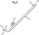
- FIG. 5 a taken out of the Garausmuffel 1 guide element 11 is shown.
- the bearing pin 27 is formed on a rod end of the guide member 11 with a reduced diameter. Since the guide element 11 consists of a solid material, manufacturing technology can be easily formed, for example by means of a lathe of the bearing pin 27 at the rod end.
- the provided with the bearing pin 27 rod end of the guide member 11 is also bent angularly. A bending necessary for this purpose is compared to a hollow material in the solid material used here, manufacturing technology easily feasible.
- the guide elements 11 and telescopic extensions are each formed independently of each other and inserted into the muffle 1, as is apparent from the FIG. 1 is apparent. Accordingly, they can be taken independently of each other from the oven, unless they are needed to hold a food support. As a result, a material entry into the cooking appliance muffle 1 can be kept as low as possible in terms of heat technology.
- the L-shaped guide element 11 is formed with a leg along the muffle side wall 9 elongated leg, which serves for guiding and supporting of insertion parts.
- the L-shape of the guide element 11 makes it possible to support the guide element 11 with its muffle back-side bar end 54 on the muffle rear wall 17 and with the bent muffle front side bar end on the muffle side wall 9. By this holder on two different muffle walls, the guide member 11 is more resistant to tilting moments.
- Muffle front side is provided on the guide member 11, a height stop 53 as a tilt protection for insertion parts. This is pressed as a bent steel wire bracket with its two ends in corresponding holes of the guide member 11. Accordingly, a further bore in the guide element 11 is formed in the region of the muffle backside rod end 54 offset by 90 °. In this a steel pin is pressed, which serves as a slot stop 55 for an insertion part.
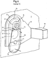
- FIG. 6 an alternative use of the bearing bush 15 is shown. Accordingly, no rod-shaped guide member 11 is inserted into the bearing bush 15 and held there by means of the latching connection.
- the telescopic extension formed with a holding plate or an adapter 57 which is mounted in the annular groove 33 of the bearing bush 15.
- the adapter 57 is spot-welded to a stationary rail 58 of the telescopic extension, for example.
- a rear pin 61 is formed for mounting on the muffle back wall 17, as in the FIG. 1 is shown.
- the pin 61 is formed like the rear rod end 54 of the guide elements 11.
- According to the FIG. 1 is mounted on the stationary rail 58 via ball bearings, not shown, a movable rail 59. On the movable rail 59, a food support can be supported.
- the muffle front side holding plate 57 is formed as a steel sheet with a punched slot 63.
- the slot 63 extends perpendicular to the elongated telescopic extension 59 and serves to hook the retaining plate 57 into the annular groove 33 of the bearing bushing 15.
- the slot 63 is punched like an inverted keyhole with a widened insertion section 65 and a narrow securing section 67 in the holding plate 57 ,
- the diameter of the widened insertion section 65 is greater than the diameter of the front flange 31 of the bearing bushing 15.
- the retaining plate 57 can be easily guided over the front flange 31 of the bearing bush 15 and hooked into the annular groove 33.
- the wall thickness of the holding plate 57 is smaller than a groove width of the annular groove 33 of the bearing bushing 15.
- the opposite lateral boundary edges of the securing portion 67 are in the FIG. 6 disposed within the annular groove 33 of the bearing bush 15. As a result, an axial movement of the suspended holding plate 57 along the bearing bush 15 is prevented.
- a leaf spring 69 is riveted by means of a rivet 71 with the retaining plate 57.
- the leaf spring 69 acts like a locking element.
- FIG. 6 the leaf spring 69 is shown in its locking position. In this position, an upper locking edge 73 of the leaf spring 69 is in contact with a periphery of the front flange 31 of the bearing bush 15 or slightly spaced therefrom. An accidental movement of the holding plate 57 upwards is thus prevented by the leaf spring 69. Accordingly, therefore accidental release of the holding plate 57 is prevented by the bearing bush 15.
- the leaf spring 69 has according to the FIG. 6 an operating portion 75. This can be pressed in the direction of the arrow shown, whereby the locking edge 73 is pivoted in the direction of the arrow shown in the cooking chamber. In this position, the locking edge 73 of the leaf spring 69 is out of engagement with the bearing bushing 15.
- the holding plate 57 of the telescopic extension 59 can therefore be raised for removal of the telescopic extension 59, so that the bearing bush 15 can be led out of the insertion section 65 of the support plate 57.
- the leaf spring 69 When removed telescopic extension 59, the leaf spring 69 is located with its locking edge 73 directly on the support plate 57 and overlaps the insertion section 65 of the slot 63.
- the bearing bush 15 For re-attaching the telescopic extension 59, the bearing bush 15 through the slot insertion section 65 of the support plate 57 to lead. In this way, the bearing bush 15 pushes the leaf spring 69 with its locking edge 73 of the holding plate 57 away.
- the telescopic extension 59 can be slightly lowered by the user until the bearing bush 15 is in the narrow securing portion 67 of the elongated hole 63, as shown in the FIG. 6 is shown.
- the leaf spring 69 is automatically jumped back into its locking position.
- the leaf spring 69 can not be tilted from the locking position to an unlocking position until a user presses on their operating portion 75.
- the holding plate 57 of the telescopic extension 59 can be raised slightly by the user.
- the bearing bush 15 is arranged in the insertion section 65 of the elongated hole 63.
- the holding plate 59 can be released by an axial movement of the bearing bush 15.
- FIGS. 7 and 8 are concerned with the storage of the rod-shaped guide member 11 and the bearing pin 61 of the telescopic extension 59 on the rear side wall of the cooking appliance muffle 1.
- each side a wall element 21 is arranged with corresponding mounting holes 19.
- the guide elements 11 and the telescopic extensions 59 are mounted in the manner of a floating bearing. This means that the respective rod end or the bearing journal 61 can move in a depth direction and thus heat-related Voltages are avoided.
- the wall element 21 is according to the FIG. 8 formed as an angled U-profile part of a steel sheet with a large heat-resistant rigidity.
- the U-profile part 21 has at its one leg a right angle bent abutment flange 77. This is mounted over locking screws 79 over a large area in contact with a mounting surface of a muffle back wall side air guide plate 81.
- the air guide plate 81 separates a ring heater, not shown, and a fan from the cooking chamber. As a result of this mounting on the air guide plate 81, it is achieved that no additional openings have to be formed for fastening the U-profile part 81, for mounting the telescopic extension 59 or for mounting the guide element 11 in the muffle rear wall 17.
- the rear side wall of the cooking appliance muffle 1 is according to the FIGS. 7 and 8 from the muffle rear wall 17, the air guide plate 81 and the garrauminnen remedyen wall elements 21st
- the angled U-profile part 21 also has a mounting flange 83. This is offset relative to the abutment flange 77 in the direction of the cooking chamber.
- the mounting holes 19 for the guide elements 11 and for the bearing pin 61 of the telescopic extension 59 are formed in a vertical row.
- each of the mounting holes 19 includes a cup-shaped edge embossing or a collar 85 which projects into the cooking chamber. This collar 85 serves as an abutting edge during the insertion of the bearing journal 61 or of the rod end 54.
- an additional aperture 87 is set on the wall element 21 in order to shield the U-profile part 21 from the cooking space.
- the panel 87 is designed as a U-shaped sheet steel profile part, which has corresponding to the mounting holes 19 of the U-profile part 21 aperture 89. Their diameter is made slightly larger than the diameter of the collar 85 of the mounting opening 19.
- the cup-shaped collar 85 protrudes in the assembled state according to the FIG. 7 through the aperture 89 in the oven.
- the collar 85 can thus fulfill its function as an insertion aid for the bearing journal 61 or the rod end 54.
- the cooking chamber facing surface of the aperture 87 is surface-finished according to the muffle walls, d. H. provided in the present case with an enamel layer.
- the aperture 87 together with the wall element 23 optically largely fades into the background.
- the aperture 87 is not directly in contact with the air guide plate 81. Rather, the aperture is slightly, d. H. spaced at least non-contact from the air guide plate 81. Corresponding damage to the enamel layer of the air guide plate 81 through the aperture 87 can be avoided.
- FIG. 9 shown second embodiment is substantially identical to the first embodiment of the FIGS. 1 to 8 ,
- the holding element 15 is designed as a holding bolt 15, which is screwed into the mounting opening 10 of the muffle side wall 9.
- the mounting bolt 15 is identical except for the insertion opening 25 with the bearing bush 15 of the first embodiment. It can therefore be hung only with its adapter 57 in the support pin 15, the telescopic extension. Inserting a guide element 11, however, is not possible.
- the stationary lower rail 58 U-shaped profile In the FIG. 9 is the stationary lower rail 58 U-shaped profile. Within the stationary lower rail 58, an intermediate rail is mounted. This connects via indicated ball bearings, the stationary lower rail 58 with the movable upper rail 59. On a side leg of the fixed rail 58 of the adapter 57 is welded. The adapter 57 is mounted with its keyhole-like slot 63 in the support pin 15. In this case, the adapter 57 is suspended in the annular groove 33 and engages behind the front flange 31 of the support bolt 15. The telescopic extension can not be accidentally pulled in the axial direction of the support pin 15.
- leaf spring 69 is shown in its locking position. In this position, the leaf spring 69 with its locking edge 73 almost in contact with the front flange 31 of the support bolt 15. The telescopic extension is therefore almost free of play and inextricably connected to the support bolt 15 in the locking position of the leaf spring 69.
- the leaf spring 69 is riveted to the adapter 57.
- the leaf spring 69 overlaps the widened portion 65 of the elongated hole 63.
- the support pin 15 is first to guide through the widened portion 65 of the slot 63 until the adapter 57 abuts the edge flange 23 of the support bolt. In this case, the support pin 15 presses the leaf spring 69 in its unlocked position. Then the telescopic extension is lowered until the adapter 57 engages behind the front flange 31 and the leaf spring 69 springs back into its locking position.
- the leaf spring 69 is pressed via its operating portion 75 in its unlocked position.
- the actuating portion 75 is arranged below the stationary rail 58 for easy access.
- the telescopic extension can be raised until the support pin 15 is in the widened portion 65 of the slot 63. In this position, the adapter 57 of the telescopic extension can be easily pulled from the mounting bolt 15.
- the adapter 57 is formed with a retaining flange 71.
- the retaining flange 71 is with its beaded peripheral edge 72 in abutment with the muffle side wall 9.
- the slot 63 is formed for hanging.
- the leaf spring 63 is riveted to the retaining flange 71 of the adapter 57.
Landscapes
- Engineering & Computer Science (AREA)
- Chemical & Material Sciences (AREA)
- Combustion & Propulsion (AREA)
- Mechanical Engineering (AREA)
- General Engineering & Computer Science (AREA)
- Baking, Grill, Roasting (AREA)
- Food-Manufacturing Devices (AREA)
Claims (15)
- Appareil ménager, en particulier appareil de cuisson avec un moufle d'appareil (1) et une pièce de suspension (58, 59), dans lequel un élément de retenue (15) pour la suspension de la pièce de suspension (58, 59) est prévu dans une paroi de moufle (9) du moufle d'appareil (1), dans lequel un élément de réglage (69) est prévu, lequel est en mesure de maintenir la pièce de suspension (58, 59) de manière fixe sur l'élément de retenue (15) dans une position de verrouillage, et dans lequel l'élément de réglage (69) peut être placé au départ de la position de verrouillage dans une position de déverrouillage, dans laquelle l'élément de réglage (69) permet de détacher la pièce de suspension (58, 59) de l'élément de retenue (15), caractérisé en ce que l'élément de réglage (69) est exécuté sous la forme d'un élément à ressort.
- Appareil ménager selon la revendication 1, caractérisé en ce qu'un retrait (33) pour la suspension de la pièce de suspension (58, 59) est exécuté dans l'élément de retenue (15).
- Appareil ménager selon l'une des revendications précédentes, caractérisé en ce que la pièce de suspension (58, 59) est maintenue sur la paroi de moufle (9), l'élément de réglage (69) étant maintenu sur la pièce de suspension (58, 59).
- Appareil ménager selon l'une des revendications précédentes, caractérisé en ce que l'élément de réglage (69) se trouve essentiellement en butée contre l'élément de retenue (15) en position de verrouillage.
- Appareil ménager selon l'une des revendications précédentes, caractérisé en ce que la pièce de suspension (11) ou l'élément de retenue (15) est exécuté(e) avec un évidement (63) pour la suspension.
- Appareil ménager selon la revendication 5, caractérisé en ce que l'élément de réglage (69) chevauche au moins partiellement l'évidement (63).
- Appareil ménager selon l'une des revendications 5 ou 6, caractérisé en ce que l'évidement (63) est exécuté sous la forme d'un trou oblong.
- Appareil ménager selon l'une des revendications 5 à 7, caractérisé en ce que l'évidement (63) est exécuté sous la forme d'un trou de serrure avec une section d'insertion (65) évasée pour la traversée de l'élément de retenue (15).
- Appareil ménager selon l'une des revendications précédentes, caractérisé en ce que la pièce de suspension (58, 59) est maintenue sur la paroi de moufle (9), dans lequel la pièce de suspension (58, 59) est un coulissant télescopique ou un système extractible avec un rail fixe (58) pour la suspension dans l'élément de retenue (15).
- Appareil ménager selon l'une des revendications précédentes, caractérisé en ce que la pièce de suspension (58, 59) est maintenue sur la paroi de moufle (9), un adaptateur (57) étant affecté à la pièce de suspension (58, 59) pour la suspension dans l'élément de retenue (15).
- Appareil ménager selon l'une des revendications précédentes, caractérisé en ce que l'élément de réglage (69) présente une section d'actionnement (75) pour le déplacement entre la position de déverrouillage et la position de verrouillage.
- Appareil ménager selon la revendication 11, caractérisé en ce que la section d'actionnement (75) de l'élément de réglage (69) est disposée en décalage transversal par rapport à la pièce de suspension (58, 59).
- Appareil ménager selon la revendication 11 ou 12, caractérisé en ce que la section d'actionnement (75) de l'élément de réglage (69) est disposée sous la pièce de suspension (58, 59).
- Appareil ménager selon la revendication 10 ou selon l'une des revendications 11 à 13 en lien avec la revendication 10, caractérisé en ce que l'adaptateur (57) de la pièce de suspension (58, 59) est en butée contre la paroi latérale de moufle (9).
- Appareil ménager selon la revendication 10 ou 14 ou selon l'une des revendications 11 à 13 en lien avec la revendication 10, caractérisé en ce qu'une fente de montage (73) essentiellement séparée de l'espace de cuisson est constituée entre l'adaptateur (57) et la paroi latérale de moufle (9).
Applications Claiming Priority (8)
| Application Number | Priority Date | Filing Date | Title |
|---|---|---|---|
| DE200410001686 DE102004001686A1 (de) | 2004-01-12 | 2004-01-12 | Haushaltsgerät, insbesondere Gargerät |
| DE200410001683 DE102004001683A1 (de) | 2004-01-12 | 2004-01-12 | Haushaltsgerät, insbesondere Gargerät sowie Herstellungsverfahren |
| DE102004001685A DE102004001685A1 (de) | 2004-01-12 | 2004-01-12 | Haushaltsgerät, insbesondere Gargerät |
| DE4016861 | 2004-01-12 | ||
| DE200410001684 DE102004001684A1 (de) | 2004-01-12 | 2004-01-12 | Haushaltsgerät, insbesondere Gargerät |
| DE4016851 | 2004-01-12 | ||
| DE4016841 | 2004-01-12 | ||
| DE40416831 | 2004-01-12 |
Publications (3)
| Publication Number | Publication Date |
|---|---|
| EP1553347A2 EP1553347A2 (fr) | 2005-07-13 |
| EP1553347A3 EP1553347A3 (fr) | 2012-02-15 |
| EP1553347B1 true EP1553347B1 (fr) | 2019-01-16 |
Family
ID=34595994
Family Applications (2)
| Application Number | Title | Priority Date | Filing Date |
|---|---|---|---|
| EP04002458A Withdrawn EP1553348A3 (fr) | 2004-01-12 | 2004-02-04 | Appareil de menage, en spéciale une cuisinière |
| EP04002457.2A Expired - Lifetime EP1553347B1 (fr) | 2004-01-12 | 2004-02-04 | Appareil de menage, en spéciale une cuisinère |
Family Applications Before (1)
| Application Number | Title | Priority Date | Filing Date |
|---|---|---|---|
| EP04002458A Withdrawn EP1553348A3 (fr) | 2004-01-12 | 2004-02-04 | Appareil de menage, en spéciale une cuisinière |
Country Status (3)
| Country | Link |
|---|---|
| EP (2) | EP1553348A3 (fr) |
| ES (1) | ES2711326T3 (fr) |
| TR (1) | TR201901653T4 (fr) |
Cited By (3)
| Publication number | Priority date | Publication date | Assignee | Title |
|---|---|---|---|---|
| US12035845B1 (en) | 2023-04-26 | 2024-07-16 | Sharkninja Operating Llc | Systems and methods for cooking pizza |
| US12372247B2 (en) | 2023-04-26 | 2025-07-29 | Sharkninja Operating Llc | Systems and methods for cooking pizza |
| USD1104596S1 (en) | 2023-05-31 | 2025-12-09 | Sharkninja Operating Llc | Cooking device |
Family Cites Families (12)
| Publication number | Priority date | Publication date | Assignee | Title |
|---|---|---|---|---|
| DE7200092U (de) * | 1973-06-07 | Miele & Cie | Kuchenherd mit Backblechablage | |
| US1946532A (en) * | 1932-01-11 | 1934-02-13 | Union Steel Prod Co | Rack for refrigerators, ovens, and the like |
| US2459446A (en) * | 1945-06-01 | 1949-01-18 | Joe H Meredith | Roller bracket for round refrigerator or cabinet shelf |
| US2466360A (en) * | 1945-12-15 | 1949-04-05 | Union Steel Prod Co | Rack assembly for refrigerators, ovens, and the like |
| US2620254A (en) * | 1950-02-24 | 1952-12-02 | Seeger Refrigerator Co | Adjustable shelf construction for refrigerator cabinets |
| US2875016A (en) * | 1954-07-22 | 1959-02-24 | Gen Motors Corp | Domestic appliances |
| FR1458666A (fr) * | 1965-10-01 | 1966-03-04 | Usines Du Pied Selle Sa Des | Dispositif de fixation des supports amovibles |
| DE4243364C2 (de) * | 1992-12-21 | 2000-03-30 | Bsh Bosch Siemens Hausgeraete | Backofen |
| DE19500371A1 (de) * | 1995-01-09 | 1996-07-11 | Aeg Hausgeraete Gmbh | Backofenmuffel für Haushalts-Backöfen |
| DE10054954B4 (de) * | 2000-11-06 | 2004-10-21 | AEG Hausgeräte GmbH | Garofen mit Auszugsvorrichtung für Gargutträger |
| DE10162922A1 (de) * | 2001-12-20 | 2003-07-03 | Bsh Bosch Siemens Hausgeraete | Auszugssystem eines Haushaltsgeräts, insbesondere eines Gargeräts |
| DE10162925A1 (de) * | 2001-12-20 | 2003-07-03 | Bsh Bosch Siemens Hausgeraete | Auszugssystem eines Haushaltsgeräts, insbesondere eines Gargeräts |
-
2004
- 2004-02-04 TR TR2019/01653T patent/TR201901653T4/tr unknown
- 2004-02-04 EP EP04002458A patent/EP1553348A3/fr not_active Withdrawn
- 2004-02-04 EP EP04002457.2A patent/EP1553347B1/fr not_active Expired - Lifetime
- 2004-02-04 ES ES04002457T patent/ES2711326T3/es not_active Expired - Lifetime
Non-Patent Citations (1)
| Title |
|---|
| None * |
Cited By (4)
| Publication number | Priority date | Publication date | Assignee | Title |
|---|---|---|---|---|
| US12035845B1 (en) | 2023-04-26 | 2024-07-16 | Sharkninja Operating Llc | Systems and methods for cooking pizza |
| US12372247B2 (en) | 2023-04-26 | 2025-07-29 | Sharkninja Operating Llc | Systems and methods for cooking pizza |
| US12408792B2 (en) | 2023-04-26 | 2025-09-09 | Sharkninja Operating Llc | Systems and methods for cooking pizza |
| USD1104596S1 (en) | 2023-05-31 | 2025-12-09 | Sharkninja Operating Llc | Cooking device |
Also Published As
| Publication number | Publication date |
|---|---|
| TR201901653T4 (tr) | 2019-02-21 |
| EP1553348A3 (fr) | 2012-02-22 |
| EP1553347A3 (fr) | 2012-02-15 |
| EP1553347A2 (fr) | 2005-07-13 |
| ES2711326T3 (es) | 2019-05-03 |
| EP1553348A2 (fr) | 2005-07-13 |
Similar Documents
| Publication | Publication Date | Title |
|---|---|---|
| EP1840473B1 (fr) | Appareil ménager avec un dispositif d'extraction de télescope fixé sur un cadre porteur | |
| EP2729037B1 (fr) | Tiroir | |
| EP1642066B1 (fr) | Systeme de tablettes coulissantes permettant de recevoir des produits a cuire | |
| EP3111801B1 (fr) | Dispositif porteur pour meuble | |
| EP2106236B1 (fr) | Rail de guidage de panier pour un lave-vaisselle | |
| EP4293287B1 (fr) | Rail télescopique | |
| EP2106235B1 (fr) | Mécanisme porteur pour un panier à vaisselle | |
| EP3681347B1 (fr) | Support de panneau et tiroir | |
| EP0458254B1 (fr) | Dispositif de fixation d'une poignée à un récipient de cuisson | |
| EP1553352B1 (fr) | Appareil ménager, en particulier appareil de cuisson et procédé pour sa fabrication | |
| EP1553351B1 (fr) | Appareil ménager, en particulier appareil de cuisson | |
| EP1553349B1 (fr) | Appareil ménager, notamment un four avec un dispositf de support | |
| EP1553350B1 (fr) | Appareil de cuisson | |
| EP1553347B1 (fr) | Appareil de menage, en spéciale une cuisinère | |
| DE102012004653B4 (de) | Einhängegestell für ein Gargerät sowie Gargerät mit einem solchen Einhängegestell | |
| DE202011001589U1 (de) | Aufhängevorrichtung für Möbel | |
| EP3106759B1 (fr) | Système de suspension pour la fixation d'un hotte aspirante | |
| EP4286749B1 (fr) | Système de fixation rapide pour une glissière télescopique | |
| EP3519737B1 (fr) | Ensemble destiné à un support pour aliments à cuire comprenant un cadre support et un dispositif d'extension de rail, et appareil électroménager comprenant un tel ensemble | |
| DE102006062070B4 (de) | Gargerätevorrichtung und Gargerät | |
| EP0984126B1 (fr) | Dispositif de guidage pour une porte coulissante | |
| DE102023135875B4 (de) | Teleskopauszug mit Schnellbefestigungselementen | |
| EP1661491B1 (fr) | Cadre de support | |
| DE102023135876A1 (de) | Teleskopauszug mit Aushebesicherung | |
| DE102012208659B4 (de) | Halteeinrichtung für eine Türscheibe einer Gargerätetür und Gargerätetür |
Legal Events
| Date | Code | Title | Description |
|---|---|---|---|
| PUAI | Public reference made under article 153(3) epc to a published international application that has entered the european phase |
Free format text: ORIGINAL CODE: 0009012 |
|
| AK | Designated contracting states |
Kind code of ref document: A2 Designated state(s): AT BE BG CH CY CZ DE DK EE ES FI FR GB GR HU IE IT LI LU MC NL PT RO SE SI SK TR |
|
| AX | Request for extension of the european patent |
Extension state: AL LT LV MK |
|
| PUAL | Search report despatched |
Free format text: ORIGINAL CODE: 0009013 |
|
| AK | Designated contracting states |
Kind code of ref document: A3 Designated state(s): AT BE BG CH CY CZ DE DK EE ES FI FR GB GR HU IE IT LI LU MC NL PT RO SE SI SK TR |
|
| AX | Request for extension of the european patent |
Extension state: AL LT LV MK |
|
| RIC1 | Information provided on ipc code assigned before grant |
Ipc: F25D 25/02 20060101ALI20120112BHEP Ipc: F24C 15/16 20060101AFI20120112BHEP |
|
| 17P | Request for examination filed |
Effective date: 20120816 |
|
| AKX | Designation fees paid |
Designated state(s): AT BE BG CH CY CZ DE DK EE ES FI FR GB GR HU IE IT LI LU MC NL PT RO SE SI SK TR |
|
| RAP1 | Party data changed (applicant data changed or rights of an application transferred) |
Owner name: BSH HAUSGERAETE GMBH |
|
| 17Q | First examination report despatched |
Effective date: 20160311 |
|
| STAA | Information on the status of an ep patent application or granted ep patent |
Free format text: STATUS: EXAMINATION IS IN PROGRESS |
|
| GRAP | Despatch of communication of intention to grant a patent |
Free format text: ORIGINAL CODE: EPIDOSNIGR1 |
|
| STAA | Information on the status of an ep patent application or granted ep patent |
Free format text: STATUS: GRANT OF PATENT IS INTENDED |
|
| INTG | Intention to grant announced |
Effective date: 20180907 |
|
| GRAS | Grant fee paid |
Free format text: ORIGINAL CODE: EPIDOSNIGR3 |
|
| GRAA | (expected) grant |
Free format text: ORIGINAL CODE: 0009210 |
|
| STAA | Information on the status of an ep patent application or granted ep patent |
Free format text: STATUS: THE PATENT HAS BEEN GRANTED |
|
| AK | Designated contracting states |
Kind code of ref document: B1 Designated state(s): AT BE BG CH CY CZ DE DK EE ES FI FR GB GR HU IE IT LI LU MC NL PT RO SE SI SK TR |
|
| REG | Reference to a national code |
Ref country code: GB Ref legal event code: FG4D Free format text: NOT ENGLISH |
|
| REG | Reference to a national code |
Ref country code: CH Ref legal event code: EP Ref country code: CH Ref legal event code: PK Free format text: BERICHTIGUNGEN |
|
| REG | Reference to a national code |
Ref country code: IE Ref legal event code: FG4D Free format text: LANGUAGE OF EP DOCUMENT: GERMAN |
|
| REG | Reference to a national code |
Ref country code: DE Ref legal event code: R096 Ref document number: 502004015761 Country of ref document: DE |
|
| RIC2 | Information provided on ipc code assigned after grant |
Ipc: F24C 15/16 20060101AFI20120112BHEP Ipc: F25D 25/02 20060101ALI20120112BHEP |
|
| REG | Reference to a national code |
Ref country code: AT Ref legal event code: REF Ref document number: 1089964 Country of ref document: AT Kind code of ref document: T Effective date: 20190215 |
|
| PGFP | Annual fee paid to national office [announced via postgrant information from national office to epo] |
Ref country code: ES Payment date: 20190319 Year of fee payment: 16 Ref country code: DE Payment date: 20190228 Year of fee payment: 16 Ref country code: FR Payment date: 20190311 Year of fee payment: 16 |
|
| REG | Reference to a national code |
Ref country code: ES Ref legal event code: FG2A Ref document number: 2711326 Country of ref document: ES Kind code of ref document: T3 Effective date: 20190503 |
|
| REG | Reference to a national code |
Ref country code: NL Ref legal event code: MP Effective date: 20190116 |
|
| PGFP | Annual fee paid to national office [announced via postgrant information from national office to epo] |
Ref country code: TR Payment date: 20190311 Year of fee payment: 16 |
|
| PG25 | Lapsed in a contracting state [announced via postgrant information from national office to epo] |
Ref country code: NL Free format text: LAPSE BECAUSE OF FAILURE TO SUBMIT A TRANSLATION OF THE DESCRIPTION OR TO PAY THE FEE WITHIN THE PRESCRIBED TIME-LIMIT Effective date: 20190116 |
|
| PG25 | Lapsed in a contracting state [announced via postgrant information from national office to epo] |
Ref country code: PT Free format text: LAPSE BECAUSE OF FAILURE TO SUBMIT A TRANSLATION OF THE DESCRIPTION OR TO PAY THE FEE WITHIN THE PRESCRIBED TIME-LIMIT Effective date: 20190516 Ref country code: SE Free format text: LAPSE BECAUSE OF FAILURE TO SUBMIT A TRANSLATION OF THE DESCRIPTION OR TO PAY THE FEE WITHIN THE PRESCRIBED TIME-LIMIT Effective date: 20190116 Ref country code: FI Free format text: LAPSE BECAUSE OF FAILURE TO SUBMIT A TRANSLATION OF THE DESCRIPTION OR TO PAY THE FEE WITHIN THE PRESCRIBED TIME-LIMIT Effective date: 20190116 |
|
| PG25 | Lapsed in a contracting state [announced via postgrant information from national office to epo] |
Ref country code: GR Free format text: LAPSE BECAUSE OF FAILURE TO SUBMIT A TRANSLATION OF THE DESCRIPTION OR TO PAY THE FEE WITHIN THE PRESCRIBED TIME-LIMIT Effective date: 20190417 Ref country code: BG Free format text: LAPSE BECAUSE OF FAILURE TO SUBMIT A TRANSLATION OF THE DESCRIPTION OR TO PAY THE FEE WITHIN THE PRESCRIBED TIME-LIMIT Effective date: 20190416 |
|
| REG | Reference to a national code |
Ref country code: CH Ref legal event code: PL |
|
| REG | Reference to a national code |
Ref country code: DE Ref legal event code: R097 Ref document number: 502004015761 Country of ref document: DE |
|
| PG25 | Lapsed in a contracting state [announced via postgrant information from national office to epo] |
Ref country code: LU Free format text: LAPSE BECAUSE OF NON-PAYMENT OF DUE FEES Effective date: 20190204 Ref country code: IT Free format text: LAPSE BECAUSE OF FAILURE TO SUBMIT A TRANSLATION OF THE DESCRIPTION OR TO PAY THE FEE WITHIN THE PRESCRIBED TIME-LIMIT Effective date: 20190116 Ref country code: RO Free format text: LAPSE BECAUSE OF FAILURE TO SUBMIT A TRANSLATION OF THE DESCRIPTION OR TO PAY THE FEE WITHIN THE PRESCRIBED TIME-LIMIT Effective date: 20190116 Ref country code: SK Free format text: LAPSE BECAUSE OF FAILURE TO SUBMIT A TRANSLATION OF THE DESCRIPTION OR TO PAY THE FEE WITHIN THE PRESCRIBED TIME-LIMIT Effective date: 20190116 Ref country code: MC Free format text: LAPSE BECAUSE OF FAILURE TO SUBMIT A TRANSLATION OF THE DESCRIPTION OR TO PAY THE FEE WITHIN THE PRESCRIBED TIME-LIMIT Effective date: 20190116 Ref country code: DK Free format text: LAPSE BECAUSE OF FAILURE TO SUBMIT A TRANSLATION OF THE DESCRIPTION OR TO PAY THE FEE WITHIN THE PRESCRIBED TIME-LIMIT Effective date: 20190116 Ref country code: EE Free format text: LAPSE BECAUSE OF FAILURE TO SUBMIT A TRANSLATION OF THE DESCRIPTION OR TO PAY THE FEE WITHIN THE PRESCRIBED TIME-LIMIT Effective date: 20190116 Ref country code: CZ Free format text: LAPSE BECAUSE OF FAILURE TO SUBMIT A TRANSLATION OF THE DESCRIPTION OR TO PAY THE FEE WITHIN THE PRESCRIBED TIME-LIMIT Effective date: 20190116 |
|
| REG | Reference to a national code |
Ref country code: BE Ref legal event code: MM Effective date: 20190228 |
|
| PLBE | No opposition filed within time limit |
Free format text: ORIGINAL CODE: 0009261 |
|
| STAA | Information on the status of an ep patent application or granted ep patent |
Free format text: STATUS: NO OPPOSITION FILED WITHIN TIME LIMIT |
|
| REG | Reference to a national code |
Ref country code: IE Ref legal event code: MM4A |
|
| 26N | No opposition filed |
Effective date: 20191017 |
|
| GBPC | Gb: european patent ceased through non-payment of renewal fee |
Effective date: 20190416 |
|
| PG25 | Lapsed in a contracting state [announced via postgrant information from national office to epo] |
Ref country code: LI Free format text: LAPSE BECAUSE OF NON-PAYMENT OF DUE FEES Effective date: 20190228 Ref country code: CH Free format text: LAPSE BECAUSE OF NON-PAYMENT OF DUE FEES Effective date: 20190228 |
|
| PG25 | Lapsed in a contracting state [announced via postgrant information from national office to epo] |
Ref country code: GB Free format text: LAPSE BECAUSE OF NON-PAYMENT OF DUE FEES Effective date: 20190416 Ref country code: IE Free format text: LAPSE BECAUSE OF NON-PAYMENT OF DUE FEES Effective date: 20190204 |
|
| PG25 | Lapsed in a contracting state [announced via postgrant information from national office to epo] |
Ref country code: SI Free format text: LAPSE BECAUSE OF FAILURE TO SUBMIT A TRANSLATION OF THE DESCRIPTION OR TO PAY THE FEE WITHIN THE PRESCRIBED TIME-LIMIT Effective date: 20190116 Ref country code: BE Free format text: LAPSE BECAUSE OF NON-PAYMENT OF DUE FEES Effective date: 20190228 |
|
| REG | Reference to a national code |
Ref country code: AT Ref legal event code: MM01 Ref document number: 1089964 Country of ref document: AT Kind code of ref document: T Effective date: 20190204 |
|
| PG25 | Lapsed in a contracting state [announced via postgrant information from national office to epo] |
Ref country code: AT Free format text: LAPSE BECAUSE OF NON-PAYMENT OF DUE FEES Effective date: 20190204 |
|
| REG | Reference to a national code |
Ref country code: DE Ref legal event code: R119 Ref document number: 502004015761 Country of ref document: DE |
|
| PG25 | Lapsed in a contracting state [announced via postgrant information from national office to epo] |
Ref country code: DE Free format text: LAPSE BECAUSE OF NON-PAYMENT OF DUE FEES Effective date: 20200901 Ref country code: FR Free format text: LAPSE BECAUSE OF NON-PAYMENT OF DUE FEES Effective date: 20200229 |
|
| PG25 | Lapsed in a contracting state [announced via postgrant information from national office to epo] |
Ref country code: CY Free format text: LAPSE BECAUSE OF FAILURE TO SUBMIT A TRANSLATION OF THE DESCRIPTION OR TO PAY THE FEE WITHIN THE PRESCRIBED TIME-LIMIT Effective date: 20190116 |
|
| PG25 | Lapsed in a contracting state [announced via postgrant information from national office to epo] |
Ref country code: HU Free format text: LAPSE BECAUSE OF FAILURE TO SUBMIT A TRANSLATION OF THE DESCRIPTION OR TO PAY THE FEE WITHIN THE PRESCRIBED TIME-LIMIT; INVALID AB INITIO Effective date: 20040204 |
|
| PG25 | Lapsed in a contracting state [announced via postgrant information from national office to epo] |
Ref country code: ES Free format text: LAPSE BECAUSE OF NON-PAYMENT OF DUE FEES Effective date: 20200205 |
|
| PG25 | Lapsed in a contracting state [announced via postgrant information from national office to epo] |
Ref country code: TR Free format text: LAPSE BECAUSE OF NON-PAYMENT OF DUE FEES Effective date: 20200204 |