EP1553355A1 - Entfeuchtungselement - Google Patents
Entfeuchtungselement Download PDFInfo
- Publication number
- EP1553355A1 EP1553355A1 EP02749366A EP02749366A EP1553355A1 EP 1553355 A1 EP1553355 A1 EP 1553355A1 EP 02749366 A EP02749366 A EP 02749366A EP 02749366 A EP02749366 A EP 02749366A EP 1553355 A1 EP1553355 A1 EP 1553355A1
- Authority
- EP
- European Patent Office
- Prior art keywords
- air ventilation
- ventilation passages
- air
- dehumidification unit
- cooling
- Prior art date
- Legal status (The legal status is an assumption and is not a legal conclusion. Google has not performed a legal analysis and makes no representation as to the accuracy of the status listed.)
- Withdrawn
Links
Images



















Classifications
-
- B—PERFORMING OPERATIONS; TRANSPORTING
- B01—PHYSICAL OR CHEMICAL PROCESSES OR APPARATUS IN GENERAL
- B01D—SEPARATION
- B01D53/00—Separation of gases or vapours; Recovering vapours of volatile solvents from gases; Chemical or biological purification of waste gases, e.g. engine exhaust gases, smoke, fumes, flue gases, aerosols
- B01D53/02—Separation of gases or vapours; Recovering vapours of volatile solvents from gases; Chemical or biological purification of waste gases, e.g. engine exhaust gases, smoke, fumes, flue gases, aerosols by adsorption, e.g. preparative gas chromatography
- B01D53/04—Separation of gases or vapours; Recovering vapours of volatile solvents from gases; Chemical or biological purification of waste gases, e.g. engine exhaust gases, smoke, fumes, flue gases, aerosols by adsorption, e.g. preparative gas chromatography with stationary adsorbents
- B01D53/0407—Constructional details of adsorbing systems
- B01D53/0446—Means for feeding or distributing gases
-
- B—PERFORMING OPERATIONS; TRANSPORTING
- B01—PHYSICAL OR CHEMICAL PROCESSES OR APPARATUS IN GENERAL
- B01D—SEPARATION
- B01D53/00—Separation of gases or vapours; Recovering vapours of volatile solvents from gases; Chemical or biological purification of waste gases, e.g. engine exhaust gases, smoke, fumes, flue gases, aerosols
- B01D53/26—Drying gases or vapours
- B01D53/261—Drying gases or vapours by adsorption
-
- F—MECHANICAL ENGINEERING; LIGHTING; HEATING; WEAPONS; BLASTING
- F24—HEATING; RANGES; VENTILATING
- F24F—AIR-CONDITIONING; AIR-HUMIDIFICATION; VENTILATION; USE OF AIR CURRENTS FOR SCREENING
- F24F13/00—Details common to, or for air-conditioning, air-humidification, ventilation or use of air currents for screening
- F24F13/30—Arrangement or mounting of heat-exchangers
-
- F—MECHANICAL ENGINEERING; LIGHTING; HEATING; WEAPONS; BLASTING
- F24—HEATING; RANGES; VENTILATING
- F24F—AIR-CONDITIONING; AIR-HUMIDIFICATION; VENTILATION; USE OF AIR CURRENTS FOR SCREENING
- F24F3/00—Air-conditioning systems in which conditioned primary air is supplied from one or more central stations to distributing units in the rooms or spaces where it may receive secondary treatment; Apparatus specially designed for such systems
- F24F3/12—Air-conditioning systems in which conditioned primary air is supplied from one or more central stations to distributing units in the rooms or spaces where it may receive secondary treatment; Apparatus specially designed for such systems characterised by the treatment of the air otherwise than by heating and cooling
- F24F3/14—Air-conditioning systems in which conditioned primary air is supplied from one or more central stations to distributing units in the rooms or spaces where it may receive secondary treatment; Apparatus specially designed for such systems characterised by the treatment of the air otherwise than by heating and cooling by humidification; by dehumidification
- F24F3/1411—Air-conditioning systems in which conditioned primary air is supplied from one or more central stations to distributing units in the rooms or spaces where it may receive secondary treatment; Apparatus specially designed for such systems characterised by the treatment of the air otherwise than by heating and cooling by humidification; by dehumidification by absorbing or adsorbing water, e.g. using an hygroscopic desiccant
-
- F—MECHANICAL ENGINEERING; LIGHTING; HEATING; WEAPONS; BLASTING
- F28—HEAT EXCHANGE IN GENERAL
- F28D—HEAT-EXCHANGE APPARATUS, NOT PROVIDED FOR IN ANOTHER SUBCLASS, IN WHICH THE HEAT-EXCHANGE MEDIA DO NOT COME INTO DIRECT CONTACT
- F28D9/00—Heat-exchange apparatus having stationary plate-like or laminated conduit assemblies for both heat-exchange media, the media being in contact with different sides of a conduit wall
- F28D9/0062—Heat-exchange apparatus having stationary plate-like or laminated conduit assemblies for both heat-exchange media, the media being in contact with different sides of a conduit wall the conduits for one heat-exchange medium being formed by spaced plates with inserted elements
-
- B—PERFORMING OPERATIONS; TRANSPORTING
- B01—PHYSICAL OR CHEMICAL PROCESSES OR APPARATUS IN GENERAL
- B01D—SEPARATION
- B01D2253/00—Adsorbents used in seperation treatment of gases and vapours
- B01D2253/10—Inorganic adsorbents
- B01D2253/106—Silica or silicates
-
- B—PERFORMING OPERATIONS; TRANSPORTING
- B01—PHYSICAL OR CHEMICAL PROCESSES OR APPARATUS IN GENERAL
- B01D—SEPARATION
- B01D2253/00—Adsorbents used in seperation treatment of gases and vapours
- B01D2253/25—Coated, impregnated or composite adsorbents
-
- B—PERFORMING OPERATIONS; TRANSPORTING
- B01—PHYSICAL OR CHEMICAL PROCESSES OR APPARATUS IN GENERAL
- B01D—SEPARATION
- B01D2253/00—Adsorbents used in seperation treatment of gases and vapours
- B01D2253/30—Physical properties of adsorbents
- B01D2253/34—Specific shapes
- B01D2253/342—Monoliths
-
- B—PERFORMING OPERATIONS; TRANSPORTING
- B01—PHYSICAL OR CHEMICAL PROCESSES OR APPARATUS IN GENERAL
- B01D—SEPARATION
- B01D2257/00—Components to be removed
- B01D2257/80—Water
-
- B—PERFORMING OPERATIONS; TRANSPORTING
- B01—PHYSICAL OR CHEMICAL PROCESSES OR APPARATUS IN GENERAL
- B01D—SEPARATION
- B01D53/00—Separation of gases or vapours; Recovering vapours of volatile solvents from gases; Chemical or biological purification of waste gases, e.g. engine exhaust gases, smoke, fumes, flue gases, aerosols
- B01D53/02—Separation of gases or vapours; Recovering vapours of volatile solvents from gases; Chemical or biological purification of waste gases, e.g. engine exhaust gases, smoke, fumes, flue gases, aerosols by adsorption, e.g. preparative gas chromatography
- B01D53/04—Separation of gases or vapours; Recovering vapours of volatile solvents from gases; Chemical or biological purification of waste gases, e.g. engine exhaust gases, smoke, fumes, flue gases, aerosols by adsorption, e.g. preparative gas chromatography with stationary adsorbents
- B01D53/0407—Constructional details of adsorbing systems
- B01D53/0438—Cooling or heating systems
Definitions
- the present invention relates to a dehumidification unit for the dehumidification of humid air by making utilization of the adsorptive action of an adsorbent.
- Dehumidification units employing an adsorbent have been known in the prior art. Referring to Figures 35 and 36 , there is illustrated, by way of example, a structure of such a conventional dehumidification unit.
- the conventional dehumidification unit Z 0 is formed by sequentially laminating an adsorption element 31 having a large number of air ventilation passages 35, 35, ... each supporting on its interior surface an adsorbent, and a cooling element 41 having a large number of air ventilation passages 45, 45, .... in a 90-degree plane phase so that the air ventilation passages 35, 35, ... are approximately orthogonal to the air ventilation passages 45, 45, ... .
- humid air (Aa) which is a stream of air to be processed is passed through the air ventilation passages 35, 35, ... of each adsorption element 31 .
- cooling air (Ab) is passed through the air ventilation passages 45, 45, ... of each cooling element 41 .
- the moisture contained in the humid air is adsorbed by the adsorbent supported on the wall surface of the air ventilation passage 35 , and the humid air is changed into a stream of low-humidity air.
- the conventional dehumidification unit Z 0 is made up of the adsorption elements 31 and the cooling elements 41 , wherein each adsorption element 31 , composed of an air ventilation passage forming member 32 bent in the shape of a corrugated plate and a pair of tabular side-plate members 33, 33 respectively firmly attached to one surface and to the other surface of the air ventilation passage forming member 32 , is shaped like a double-sided cardboard.
- Each of the air ventilation passage forming member 32 and the side-plate members 33, 33 is formed of fiber paper made of ceramic fibers, and supports, on its surface, an adsorbent such as silica gel etcetera.
- each cooling element 41 composed of an air ventilation passage forming member 42 bent in the shape of a corrugated plate and a pair of tabular side-plate members 43, 43 respectively firmly attached to one surface and to the other surface of the air ventilation passage forming member 42 , is shaped like a double-sided cardboard.
- Each of the air ventilation passage forming member 42 and the side-plate members 43, 43 is formed from a sheet metal (thin metallic plate) made of aluminum etcetera.
- each adsorption element 31 is formed from the air ventilation passage forming member 32 in the form of a bending plate member and the first air ventilation passages 35, 35, ... have a triangular cross-sectional shape.
- each cooling element 41 is formed from the air ventilation passage forming member 42 in the form of a bending plate member and the second air ventilation passages 45, 45, ... have a triangular cross-sectional shape.
- the first air ventilation passage 35 of the adsorption element 31 is designed to have a triangular cross-sectional shape, with a view to increasing the capability of adsorption by enlarging, to the maximum extent possible, the area of contact between the to-be-processed air (Aa) flowing in the inside of the first air ventilation passage 35 and the absorbent supported on the interior surface of the first air ventilation passage 35 . There is no problem with such arrangement.
- cooling element 41 there is no need to increase the area of contact between the interior surface of the second air ventilation passage 45 and the cooling air (Ab) flowing through the second air ventilation passage 45 , unlike the adsorption element 31 , but there is the request for the efficiency of heat liberation, in other words it is required that the resistance against the flow of the cooling air (Ab) be restricted thereby to reduce the loss of pressure, and that the flow rate of the cooling air (Ab) be increased so as to increase the capacity of absorption of heat.
- the cross-sectional shape of the second air ventilation passage 45 is in the shape of a triangle, therefore being unfavorable not only in view of accomplishing improvement in the efficiency of heat liberation but also in view of accomplishing improvement in the dehumidification capability of the dehumidification unit Z 0 .
- the flow resistance of a flow path is often affected by its cross-sectional shape.
- the contact resistance of a wall surface against a stream of air is high at a sharp-angled corner, and the area in the vicinity of such a corner is a region where substantially no air flows.
- the cross-sectional shape of the second air ventilation passage 45 is triangular, the ratio of effective passage area to total passage area is small.
- the second air ventilation passage 45 whose cross-sectional shape is triangular becomes greater in flow resistance by an amount corresponding to the difference in effective passage area between the passages.
- an object of the present invention is to maintain the dehumidification capability of a dehumidification unit at high levels over a long period of time by pressure-loss reduction.
- the present invention employs the following constructions as specific means for providing solutions to the above-described problems with the prior art techniques.
- a first invention of the present application discloses a dehumidification unit comprising alternate laminations of an adsorption element 1 which supports an adsorbent and in which a plurality of first air ventilation passages 3, 3, ... through which air (Aa) to be processed flows are formed planewise in rows, and a cooling element 2 in which a plurality of second air ventilation passages 4, 4, ... through which cooling air (Ab) flows are formed planewise in rows.
- the dehumidification unit of the first invention is characterized in that: the cooling element 2 is provided, at a planewise inner area thereof, with an opening 24 , thereby being shaped like a frame; and each of the second air ventilation passages 4, 4, ... is divided by the opening 24 into an entry opening 4a and an exit opening 4b situated respectively on one passagewise side and on the other passagewise side thereof.
- a second invention of the present application discloses a dehumidification unit comprising alternate laminations of an adsorption element 1 which supports an adsorbent and in which a plurality of first air ventilation passages 3, 3, ... through which air (Aa) to be processed flows are formed planewise in rows, and a cooling element 2 in which a plurality of second air ventilation passages 4, 4, ... through which cooling air (Ab) flows are formed planewise in rows.
- the dehumidification unit of the second invention is characterized in that each of the second air ventilation passages 4, 4, ... of the cooling element 2 has an approximately rectangular cross-sectional shape.
- each of the second air ventilation passages 4, 4, ... of the cooling element 2 has an approximately rectangular cross-sectional shape.
- each of the second air ventilation passages 4, 4, ... of the cooling element 2 has an approximately triangular cross-sectional shape.
- a dehumidification unit according to any one of the first, third, and fourth inventions.
- the dehumidification unit of the fifth invention is characterized in that an air stream regulating means X , configured to inhibit the flow of the cooling air (Ab) from deviating in the inside of the opening part 24 , is disposed in the opening 24 of the cooling element 2 .
- a dehumidification unit according to any one of the first, third, and fourth inventions.
- the dehumidification unit of the sixth invention is characterized in that it further comprises a flow rate regulating means Y disposed on the side of the entry openings 4a, 4a, ... of the second air ventilation passages 4, 4, ... , whereby the flow rate of the cooling air (Ab) entering the inside of the opening 24 through each of the entry openings 4a, 4a, ... is so regulated as to become higher the nearer to the downstream side of the first air ventilation passages 3, 3, ... of the adsorption element 1 .
- a dehumidification unit according to the sixth invention.
- the dehumidification unit of the seventh invention is characterized in that the flow rate regulating means Y is formed by setting the passage length of the entry openings 4a, 4a, ... of the second air ventilation passages 4, 4, ... to become shorter the nearer to the downstream end of the first air ventilation passages 3, 3, ... .
- the passage resistance of second air ventilation passages nearer to an area 2c of the cooling element 2 corresponding to the upstream side of the first air ventilation passages 3, 3, ... of the adsorption element 1 is greater than the passage resistance of second air ventilation passages nearer to an area 2d of the cooling element 2 corresponding to the downstream side of the first air ventilation passages 3, 3, ... of the adsorption element 1 .
- a dehumidification unit according to the eighth invention.
- the dehumidification unit of the ninth invention is characterized in that the passage length of the second air ventilation passages 4, 4, ... on the downstream side of the openings 24A and 24B is set such that the passage length of second air ventilation passages nearer to the area 2c corresponding to the upstream side of the first air ventilation passages 3, 3, ... of the adsorption element 1 is greater than the passage length of second air ventilation passages nearer to the area 2d corresponding to the downstream side of the first air ventilation passages 3, 3, ... of the adsorption element 1 .
- a dehumidification unit according to the ninth invention.
- the dehumidification unit of the tenth invention is characterized in that the passage length of the second air ventilation passages 4, 4, ... is set so as to become gradually shorter from the side nearer to the area 2c corresponding to the upstream side of the first air ventilation passages 3, 3, ... of the adsorption element 1 towards the side nearer to the area 2d corresponding to the downstream side of the first air ventilation passages 3, 3, ... of the adsorption element 1 .
- the dehumidification unit of the eleventh invention is characterized in that the passage length of the second air ventilation passages 4, 4, ... is set so as to become linearly shorter from the side nearer to the area 2c corresponding to the upstream side of the first air ventilation passages 3, 3, ... of the adsorption element 1 towards the side nearer to the area 2d corresponding to the downstream side of the first air ventilation passages 3, 3, ... of the adsorption element 1.
- a dehumidification unit according to the eighth invention.
- the dehumidification unit of the thirteenth invention is characterized in that the passage cross-sectional area of the second air ventilation passages 4, 4, ... on the downstream side of the openings 24A and 24B is set such that the passage cross-sectional area of second air ventilation passages nearer to the area 2c corresponding to the upstream side of the first air ventilation passages 3, 3, ... of the adsorption element 1 is smaller than the passage cross-sectional area of second air ventilation passages 4 nearer to the area 2d corresponding to the downstream side of the first air ventilation passages 3, 3, ... of the adsorption element 1 .
- a dehumidification unit according to the ninth invention.
- the dehumidification unit of the fourteenth invention is characterized in that the passage cross-sectional area of the second air ventilation passages 4, 4, ... on the downstream side of the openings 24A and 24B is set such that the passage cross-sectional area of second air ventilation passages nearer to the area 2c corresponding to the upstream side of the first air ventilation passages 3, 3, ... of the adsorption element 1 is smaller than the passage cross-sectional area of second air ventilation passages 4 nearer to the area 2d corresponding to the downstream side of the first air ventilation passages 3, 3, ... of the adsorption element 1 .
- a fifteenth invention of the present application discloses a dehumidification unit comprising alternate laminations of an adsorption element 1 which supports an adsorbent and in which a plurality of first air ventilation passages 3, 3, ... through which air (Aa) to be processed flows are formed planewise in rows, and a cooling element 2 in which a plurality of second air ventilation passages 4, 4, ... through which cooling air (Ab) flows are formed planewise in rows.
- the dehumidification unit of the fifteenth invention is characterized in that: the cooling element 2 is provided with openings 24A and 24B which overlap with the second air ventilation passages 4, 4, ... such that the second air ventilation passages 4, 4, ... are each divided passagewise; and the passage direction of the second air ventilation passages 4, 4, ...
- a dehumidification unit according to any one of the eighth, ninth, thirteenth, and fourteenth inventions.
- the dehumidification unit of the sixteenth invention is characterized in that the passage direction of the second air ventilation passages 4, 4, ... on the downstream side of the openings 24A and 24B as viewed in plane view is inclined so as to get closer to the area 2d of the cooling element 2 corresponding to the downstream side of the first air ventilation passages 3, 3, ... of the adsorption element 1 with approach towards the downstream side.
- a dehumidification unit according to any one of the eighth, ninth, thirteenth, fourteenth, and fifteenth inventions.
- the dehumidification unit of the seventeenth invention is characterized in that a plurality of sets of the openings 24A and 24B and the second air ventilation passages 4, 4, ... situated downstream of the openings 24A and 24B are provided in a back-and-forth arrangement relative to the flow direction of the cooling air (Ab) in the cooling element 2 .
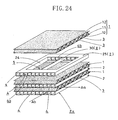
- the dehumidification unit Z 1 is a result of the embodying of inventions as set forth in claim 1 and claim 4.
- the dehumidification unit Z 1 is formed as follows: a plurality of adsorption elements 1, 1, ... and a plurality of cooling elements 2, 2, ... are laminated sequentially alternately in a 90-degree plane phase, thereby to form a laminated body.
- two end plates 9, 9 are mounted on one lamination-wise end and on the other lamination-wise end of the laminated body, respectively.
- the end plates 9, 9 are connected together by four frame members 10, 10, ...
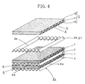
- the air ventilation passage forming member 11 is formed of fiber paper made of ceramic fibers. More specifically, the air ventilation passage forming member 11 is a bending plate member formed by alternate bending of a sheet of fiber paper in the thickness direction thereof, in other words the air ventilation passage forming member 11 is shaped, as a whole, like a corrugated plate. An adequate adsorbent, such as silica gel etcetera, is supported on a surface of the air ventilation passage forming member 11 .
- each of the side plate members 12, 12 is formed of fiber paper of ceramic fibers and is in the form of a flat plate. An adequate adsorbent, such as silica gel etcetera, is supported on one surface of each side plate member 12 and a separation sheet layer 14 is formed on the other surface.
- the side plate members 12, 12 are firmly united to the surfaces of the air ventilation passage forming member 11 so that they are combined into a single body, whereby the adsorption element 1 provided with the first air ventilation passages 3, 3, ... extending in parallel with areas corresponding to "valley" portions of the air ventilation passage forming member 11 is prepared. Accordingly, in the adsorption element 1, the first air ventilation passages 3, 3, ... formed in rows in a plane direction of the adsorption element 1 are placed in such a state that they are completely separated from the outside by the separation sheet layers 14, 14 of the side plate members 12, 12 .
- the separation sheet layer 14 is disposed to prevent the passage of gas and liquid through the side-plate member 12 , and to completely separate the first air ventilation passages 3 from second air ventilation passages 4 (described later) on the side of the cooling element 2 .
- the separation sheet layer 14 is formed by attaching a plastic film to the surface of the side-plate member 12 , by vapor-depositing a metallic material (for example, aluminum) on the surface of the side-plate member 12 , or by applying an organic binder, such as aqueous urethane resin etcetera, onto the surface of the side-plate member 12 .
- the air ventilation passage forming member 21 is made up of a bending plate member formed by alternate bending of a sheet metal of aluminum etcetera or a sheet resin in the thickness direction thereof, and is shaped like, as a whole, a corrugated plate.
- the side-plate member 22 is formed from a sheet metal of aluminum etcetera or a sheet resin, and is shaped like a flat plate.
- the side-plate member 22 is firmly united to one surface of the air ventilation passage forming member 21 , whereby the side-plate member 22 and the air ventilation passage forming member 21 are combined into a single piece. Thereafter, a portion of the combined body positioned centrally relative to the plane direction is subjected to punching, thereby to form a rectangular opening 24 . In this way, the cooling element 2 is obtained. Accordingly, the cooling element 2 is shaped, as a whole, like a rectangular frame.
- each of the second air ventilation passages thus divided is made up of an entry portion 4a on one side and an exit portion 4b on the other side.
- the entry portion 4a and the exit portion 4b face each other across the opening 24 in plane direction.
- the second air ventilation passages 4, 4, ... are each divided into an entry side portion and an exit side portion, but their intermediate portions communicate with each other in the opening 24.
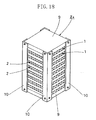
- the adsorption element 1 and the cooling element 2 are sequentially alternately laminated one upon the other in a plane phase of 90 degrees. These adsorption and cooling elements 1 and 2 are brought together into a laminated body by the end plates 9, 9 and the frame members 10, 10, ..., thereby to prepare the dehumidification unit Z 1 having a rectangular block-like outer appearance (see Figure 3).
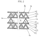
- a cooling element 2 is sandwiched between two adsorption elements 1, 1 situated on both sides of the cooling element 2 , and both opening surfaces of the opening 24 of the cooling element 2 are closed by the adsorption elements 1, 1, thereby defining an empty space 5 having a required volume (see Figure 2 ). And, the empty space 5 communicates, through the entry portions 4a, 4a, ... and through the exit portions 4b, 4b, ... , with the outside.
- the dehumidification unit Z 1 with a rectangular block-like outer appearance comprising four side surfaces (a first pair of opposing side surfaces and a second pair of opposing side surfaces).
- the first air ventilation passages 3, 3, .. . of each of the adsorption elements 1, 1, ... have opening ends at the first pair of opposing side surfaces.
- the entry portions 4a, 4a, ... of the second air ventilation passages 4, 4, ... of the cooling element 2 open at one of the second pair of opposing side surfaces.
- the exit portions 4b, 4b, ... of the second air ventilation passages 4, 4, ... of the cooling element 2 open at the other of the second pair of opposing side surfaces.
- the operation of the dehumidification unit Z 1 is described together with other relevant matters.
- humid air as air (Aa) to be processed is passed through each of the first air ventilation passages 3, 3, ... and cooling air (Ab) is passed through each of the second air ventilation passages 4, 4, ... , whereby the to-be-processed air (Aa) is dehumidified.
- cooling air (Ab) is passed through each of the second air ventilation passages 4, 4, ...
- the to-be-processed air (Aa) is dehumidified.
- the to-be-processed air (Aa) flows in the inside of each of the first air ventilation passages 3, 3, ...
- the moisture contained in the air (Aa) is sequentially adsorption-removed by the adsorbent supported on each of the first air ventilation passages 3, 3, ... and is dehumidified. Finally, the air (Aa) is discharged as a stream of low-humidity air.
- the action of heat liberation by an absorption of heat of adsorption generated on the side of adsorption element 1 is carried out by the cooling air (Ab) flowing through each of the second air ventilation passages 4, 4, ....
- the temperature of the adsorbent on the side of the adsorption element 1 is constantly maintained at adequate level. Therefore, the adsorbent will maintain its adsorption capability at high level over a long period of time.
- the dehumidification unit Z 1 will maintain its dehumidification capability at high levels over long periods.
- the dehumidification unit Z 1 of the present embodiment demonstrates high-level dehumidification capabilities because of the following structural characteristics of the cooling element 2 .
- the cooling element 2 is provided with the opening 24 .
- Each of the second air ventilation passages 4, 4, ... is divided relative to the passage direction into the entry portion 4a and the exit portion 4b by the opening 24 and its intermediate portion is the empty space 5 common to the second air ventilation passages 4, 4, ....
- the cooling air (Ab) flows into the second air ventilation passages 4, 4, ... by way of the entry portions 4a, 4a, ... and then enters the inside of the empty space 5 directly from the entry portions 4a, 4a, ....
- the cooling air (Ab) flows in a free manner toward the exit portions 4b, 4b, ... from the side of the entry portions 4a, 4a, ..., and is discharged through the exit portions 4b, 4b, ... to the outside.
- the total pressure loss of the cooling element 2 of the present embodiment is made smaller by an amount corresponding to the reduction in passage length of the second air ventilation passage 4 by the formation of the opening 24 , when compared, for example, with the case where the second air ventilation passages 4, 4, ... are each configured so as to continuously extend from one end side to the other end side of the cooling element 2 (in other words the construction without the provision of the opening 24 ).
- each second air ventilation passage 4 of the cooling element 2 has a triangular cross-sectional shape (that is to say, such a structure that the ratio of effective cross-sectional area to total cross-sectional area is small and the resistance against the flow of the cooling air (Ab) is liable to increase).
- the dehumidification unit Z 1 of the present embodiment in spite of the arrangement that the cross-sectional shape of the second air ventilation passage 4 is triangular, its pressure loss is held low. As a result, the flow rate of the cooling air (Ab) which flows through the second air ventilation passage 4 is increased, and correspondingly the heat-liberation efficiency of heat of adsorption on the side of the adsorption element 1 by the cooling air (Ab) is improved. Therefore, improvement in the dehumidification capability of the dehumidification unit Z 1 is expected.
- the entry portions 4a, 4a, ... of the second air ventilation passages 4, 4, ... are arranged on one end side of the opening 24 .
- the exit portions 4b, 4b, ... of the second air ventilation passages 4, 4, ... are arranged on the other end side of the opening 24 . Therefore, on the side of the entry portions 4a, 4a, ..., the cooling air (Ab) flowing towards the opening 24 is flow-rectified by the entry portions 4a, 4a, ... and is prevented from deviating in the direction in which the second air ventilation passages 4, 4, ... are formed in rows. As the result of this, the flow of the cooling air (Ab) in the inside of the empty space 5 is stabilized and it becomes possible to reduce the pressure loss to a further extent.
- the transfer of heat between the adsorption element 1 and the cooling element 2 is accelerated and the liberation of heat is accelerated by the increase in flow rate of the cooling air (Ab) resulting from the reduction in pressure loss. Accordingly, if the amount of heat liberation required on the side of the cooling element 2 is the same, this makes it possible to make the flow rate of the cooling air (Ab) in the empty space 5 lower by an amount corresponding to the acceleration in heat transfer and liberation.
- the thickness dimension of the cooling element 2 can be set to a smaller value.
- dehumidification unit Z 2 formed in accordance with a second embodiment of the present invention.
- the dehumidification unit Z 2 is a result of the embodying of inventions as set forth in claims 1 and 4.
- the dehumidification unit Z 2 is configured basically the same as the dehumidification unit Z 1 of the first embodiment, with the exception of the way the cooling element 2 is constructed.
- the cooling element 2 made up of the air ventilation passage forming member 21 formed from a bending plate member and the side-plate member 22 , is shaped like a single-sided cardboard.
- the cooling element 2 is made up only of the air ventilation passage forming member 21 formed from a bending plate member.
- the remaining arrangement i.e., the arrangement in which the opening 24 is formed centrally relative to the plane direction in the cooling element 2 so that the cooling element 2 is shaped, as a whole, like a frame, is the same as the cooling element 2 of the first embodiment.
- the efficiency of heat transfer between the cooling air (Ab) flowing on the side of the cooling element 2 and the adsorption element 1 the temperature of which has been increased by heat of adsorption becomes higher in comparison with the dehumidification unit Z 1 of the first embodiment in which the second air ventilation passages 4, 4, ... face, at portions corresponding to the entry portions 4a, 4a, ... and to the exit portions 4b, 4b, ..., the adsorption element 1 with the side-plate member 22 lying therebetween.
- the heat-liberation action of heat of adsorption is accelerated correspondingly and, in addition, further improvement in the dehumidification capability of the dehumidification unit Z 2 is expected.
- dehumidification unit Z 3 formed in accordance with a third embodiment of the present invention.
- the dehumidification unit Z 3 is a result of the embodying of inventions as set forth in claim 1 and claim 4.
- the dehumidification unit Z 3 is configured basically the same as the dehumidification unit Z 1 of the first embodiment, with the exception of the way the adsorption element 1 and the cooling element 2 are constructed.
- the adsorption element 1 made up of three components (i.e., an air ventilation passage forming member 11 formed from a bending plate member and a pair of side-plate members 12, 12 joined respectively to one surface and to the other surface of the air ventilation passage forming member 11 ), is shaped like a double-sided cardboard, and each side-plate number 12 is provided, on its exterior surface, with a respective separation sheet layer 14 .
- the adsorption element 1 made up of an air ventilation passage forming member 11 formed from a bending plate member and a single side-plate member 12 joined to one surface of the air ventilation passage forming member 11 , is shaped like a single-sided cardboard, and a surface of the side-plate member 12 of the adsorption element 1 and a surface of the air ventilation passage forming member 11 situated on the open side are each provided with a respective separation sheet layer 14 .
- the side-plate member 22 shaped like a flat plate is firmly joined to one surface of the air ventilation passage forming member 21 shaped like a corrugated plate, and its planewise central portion is subjected to punching, thereby to punch a hole (i.e., the rectangular opening 24 ) through an integrally combined member made up of the air ventilation passage forming member 21 and the side-plate member 22 .
- the dehumidification unit Z 3 of the present embodiment it is arranged such that only the air ventilation passage forming member 21 is subjected to punching so as to punch a rectangular hole (the opening 24 ) therethrough and the side-plate member 22 remains unprocessed at the bottom of the opening 24, although the cooling element 2 of the dehumidification unit Z 3 is formed from two different members, namely the air ventilation passage forming member 21 and the side-plate member 22 .
- the cooling element 2 is prepared as follows. The air ventilation passage forming member 21 is subjected to punching so that the opening 24 is preformed. Thereafter, the side-plate member 22 (not subjected to punching) is firmly joined to the air ventilation passage forming member 21 already provided with the opening 24 .
- the adsorption element 1 is made up of only two component members (i.e., the air ventilation passage forming member 11 and the side-plate member 12 ).
- the adsorption element 1 of the dehumidification unit Z 3 is made up of a less number of component members, and the manufacture of the adsorption element 1 is facilitated correspondingly and cost savings are provided.
- dehumidification unit Z 4 formed in accordance with a fourth embodiment of the present invention.
- the dehumidification unit Z 4 is a result of the embodying of an invention as set forth in claim 2.
- the dehumidification unit Z 4 is formed as follows: a plurality of adsorption elements 1, 1, ... and a plurality of cooling elements 2, 2, ... are laminated sequentially alternately in a 90-degree plane phase, thereby to form a laminated body. Then, two end plates 9, 9 are mounted on one lamination-wise end and on the other lamination-wise end of the laminated body, respectively.
- the end plates 9, 9 are connected together by four frame members 10, 10, ...
- the adsorption element 1 of the present embodiment is shaped like a double-sided cardboard made up of a below-mentioned air ventilation passage forming member 11 and a pair of side-plate members 12, 12 .
- the air ventilation passage forming member 11 is formed of fiber paper made of ceramic fibers. More specifically, the air ventilation passage forming member 11 is a bending plate member formed by alternate bending of a sheet of fiber paper in the thickness direction thereof, in other words the air ventilation passage forming member 11 is shaped, as a whole, like a corrugated plate. An adequate adsorbent, such as silica gel etcetera, is supported on a surface of the air ventilation passage forming member 11 .
- each of the side plate members 12, 12 is formed of fiber paper of ceramic fibers and is in the form of a flat plate. An adequate adsorbent, such as silica gel etcetera, is supported on one surface of each side plate member 12 and a separation sheet layer 14 is formed on the other surface.
- the side plate members 12, 12 are firmly united to the surfaces of the air ventilation passage forming member 11 so that they are combined into a single body, whereby the adsorption element 1 provided with the first air ventilation passages 3, 3, ... extending in parallel with areas corresponding to "valley" portions of the air ventilation passage forming member 11 is prepared. Accordingly, in the adsorption element 1, the first air ventilation passages 3, 3, ... formed in rows in a plane direction of the adsorption element 1 are placed in such a state that they are completely separated from the outside by the separation sheet layers 14, 14 of the side plate members 12, 12 .
- the cooling element 2 is made up only of a below-mentioned air ventilation passage forming member 21 .
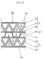
- the air ventilation passage forming member 21 is made up of a bending plate member formed by alternate bending of a sheet metal of aluminum etcetera or a sheet resin in a trapezoidal pattern in the thickness direction thereof, and is shaped like, as a whole, a trapezoidally-corrugated bending plate.
- the adsorption element 1 and the cooling element 2 are sequentially alternately laminated one upon the other in a plane phase of 90 degrees. These elements 1 and 2 are brought together into a single laminated body by the end plates 9, 9 and the frame members 10, 10, ... , thereby to prepare the dehumidification unit Z 4 having a rectangular block-like outer appearance (see Figure 9 ). As shown in Figure 8, in the dehumidification unit Z 4 thus prepared, a plurality of second air ventilation passages 4, 4, ...
- trapezoidal cross-sectional shape i.e., an approximately rectangular cross-sectional shape
- the dehumidification unit Z 4 has four side surfaces comprising a first pair of opposing side surfaces and a second pair of opposing side surfaces.
- the first air ventilation passages 3, 3, ... of each of the adsorption elements 1, 1, ... have opening ends at the first pair of opposing side surfaces.
- the second air ventilation passages 4, 4, ... of each of the cooling elements 2, 2, ... have open ends at the second pair of opposing side surfaces.
- the operation of the dehumidification unit Z 4 is described together with other relevant matters.
- humid air as air (Aa) to be processed is passed through each of the first air ventilation passages 3, 3, ... and cooling air (Ab) is passed through each of the second air ventilation passages 4, 4, ... , whereby the to-be-processed air (Aa) is dehumidified.
- cooling air (Ab) is passed through each of the second air ventilation passages 4, 4, ...
- the to-be-processed air (Aa) is dehumidified.
- the to-be-processed air (Aa) flows in the inside of each of the first air ventilation passages 3, 3, ...
- the moisture contained in the air (Aa) is sequentially adsorption-removed by the adsorbent supported on each of the first air ventilation passages 3, 3, ... and is dehumidified. Finally, the air (Aa) is discharged as a stream of low-humidity air.
- the action of heat liberation by an absorption of heat of adsorption generated on the side of adsorption element 1 is carried out by the cooling air (Ab) flowing through each of the second air ventilation passages 4, 4, ....
- the temperature of the adsorbent on the side of the adsorption element 1 is constantly maintained at adequate level. Therefore, the adsorbent will maintain its adsorption capability at high level over a long period of time.
- the dehumidification unit Z 4 will maintain its dehumidification capability at high levels over long periods.
- the dehumidification unit Z 4 of the present embodiment demonstrates high-level dehumidification capabilities because of the following structural characteristics of the cooling element 2 .
- the second air ventilation passages 4, 4, ... defined in the cooling element 2 have a trapezoidal cross-sectional shape.
- the effective passage area of each of the second air ventilation passages 4, 4, ... becomes greater than that of an air ventilation passage having the same total passage area as the second air ventilation passage 4 and having a triangular cross-sectional shape.
- the flow resistance of the second air ventilation passages 4, 4, ... is small and the pressure loss of the cooling air (Ab) flowing through the second air ventilation passages 4, 4, ... is held low.
- This makes it possible to increase the flow rate of the cooling air (Ab) in the second air ventilation passages 4, 4, ... by an amount corresponding to the reduction in pressure loss.
- the heat-liberation efficiency of heat of adsorption by the cooling air (Ab) is improved, and the dehumidification capability of the dehumidification unit Z 4 is maintained at high levels over a long period of time.
- dehumidification unit Z 5 formed in accordance with a fifth embodiment of the present invention.
- the dehumidification unit Z 5 is a result of the embodying of inventions as set forth in claim 1 and claim 3.
- the dehumidification unit Z 5 is configured basically the same as the dehumidification unit Z 4 of the fourth embodiment, with the exception of the way the cooling element 2 is constructed.
- the cooling element 2 is made up of the air ventilation passage forming member 21 formed from a bending plate member bent into a trapezoidal shape.
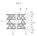
- the cooling element 2 of the dehumidification unit Z 5 is formed from a frame-like air ventilation passage forming member 21 . More specifically, the air ventilation passage forming member 21 is formed from a bending plate member bent into a trapezoidal shape and provided with an opening 24 at its planewise central portion. A plurality of second air ventilation passages 4, 4, ... extending in parallel with each other are formed in the cooling element 2 by its "valley" portions.
- each of the second air ventilation passages 4, 4, ... remain as an entry portion 4a and as an exit portion 4b respectively, and a portion other than the entry and exit portions 4a, 4b, i.e. an intermediate portion, is substituted by the opening 24 .
- the adsorption element 1 and the cooling element 2 are sequentially alternately laminated one upon the other in a plane phase of 90 degrees. These adsorption and cooling elements 1 and 2 are brought together into a laminated body by the end plates 9, 9 and the frame members 10, 10, ..., thereby to prepare the dehumidification unit Z 5 .
- a cooling element 2 is sandwiched between two adsorption elements 1, 1 situated on both sides of the cooling element 2 , and both opening surfaces of the opening 24 of the cooling element 2 are closed by the adsorption elements 1, 1 , thereby defining an empty space 5 having a required volume. And, the empty space 5 communicates, through the entry portions 4a, 4a, ... and through the exit portions 4b, 4b, ... , with the outside.
- the operation of the dehumidification unit Z 5 is described together with other relevant matters.
- humid air as air (Aa) to be processed is passed through each of the first air ventilation passages 3, 3, ... and cooling air (Ab) is passed through each of the second air ventilation passages 4, 4, ... , whereby the to-be-processed air (Aa) is dehumidified.
- cooling air (Ab) is passed through each of the second air ventilation passages 4, 4, ...
- the to-be-processed air (Aa) is dehumidified.
- the to-be-processed air (Aa) flows in the inside of each of the first air ventilation passages 3, 3, ...
- the moisture contained in the air (Aa) is sequentially adsorption-removed by the adsorbent supported on each of the first air ventilation passages 3, 3, ... and is dehumidified. Finally, the air (Aa) is discharged as a stream of low-humidity air.
- the action of heat liberation by an absorption of heat of adsorption generated on the side of adsorption element 1 is carried out by the cooling air (Ab) flowing through each of the second air ventilation passages 4, 4, ... .
- the cooling air (Ab) flowing through each of the second air ventilation passages 4, 4, ... the cooling air flowing through each of the second air ventilation passages 4, 4, ... .
- the dehumidification unit Z 5 of the present embodiment provides, in addition to the above-described basic effects, the following specific effects.
- the dehumidification unit Z 5 provides a first specific effect attributable to the cross-sectional shape of the second air ventilation passages 4, 4, ... defined in the cooling element 2 .
- the cooling element 2 is provided with the second air ventilation passages 4, 4, ... having a trapezoidal cross-sectional shape, whereby the pressure loss of the cooling air (Ab) in the cooling element 2 is lessened.
- the flow rate of the cooling air (Ab) increases, thereby improving the heat-liberation efficiency of heat of adsorption. Therefore, the dehumidification capability of the dehumidification unit Z 5 is improved to a further extent.
- the dehumidification unit Z 5 provides a second specific effect attributable to the provision of the opening 24 in the cooling element 2 .
- the cooling element 2 is provided with the opening 24 .
- Each of the second air ventilation passages 4, 4, ... is divided, relative to the passage direction, into an entry portion 4a and an exit portion 4b .
- the intermediate portion is the empty space 5 common to the second air ventilation passages 4, 4, ... .
- the total pressure loss of the cooling element 2 of the present embodiment is made smaller by an amount corresponding to the reduction in passage length of the second air ventilation passage 4 by the formation of the opening 24 , when compared, for example, with the case where the second air ventilation passages 4, 4, ... are each configured so as to continuously extend from one end side to the other end side of the cooling element 2 (in other words the construction without the provision of the opening 24 ).
- the entry portions 4a, 4a, ... of the second air ventilation passages 4, 4, ... are arranged on one end side of the opening 24 .
- the exit portions 4b, 4b, ... of the second air ventilation passages 4, 4, ... are arranged on the other end side of the opening 24 . Therefore, on the side of the entry portions 4a, 4a, ... , the cooling air (Ab) flowing towards the opening 24 is flow-rectified by the entry portions 4a, 4a, ... and is prevented from deviating in the direction in which the second air ventilation passages 4, 4, ... are formed in rows. As the result of this, the flow of the cooling air (Ab) in the inside of the empty space 5 is stabilized and it becomes possible to reduce the pressure loss to a further extent.
- the dehumidification unit Z 5 provides a third specific effect resulting from accelerating the transfer of heat between the adsorption element 1 and the cooling element 2 .
- the empty space 5 is defined by the opening 24 of the cooling element 2 , and in a corresponding portion to the empty space 5 the cooling air (Ab) in the inside of the empty space 5 is brought into direct contact with the side-plate member 12 of the adsorption element 1 .
- the dehumidification unit Z 5 made up the cooling element 2 and the adsorption element 1 is made compact in height dimension. Especially when using the dehumidification unit Z 5 as a dehumidification mechanism of an air conditioner, this contributes to the downsizing of air conditioners.
- the dehumidification unit Z 5 of the present embodiment on the side of the exit portions 4b, 4b, ... of the cooling element 2 the cooling air (Ab) flows outwardly from the empty space 5 through the exit portions 4b, 4b, ... while being flow-rectified. Therefore, the level of noise generated by the outflow of the cooling air (Ab) is held as low as possible. As the result of this, quietness during dehumidification mode operation is secured. If the dehumidification unit Z 5 is employed, for example, as a dehumidification mechanism of an air conditioner, this is preferable in view of realizing quiet air-conditioning operations.
- dehumidification unit Z 6 formed in accordance with a sixth embodiment of the present invention.
- the dehumidification unit Z 6 is a result of the embodying of an invention as set forth in claim 2.
- the dehumidification unit Z 6 is configured basically the same as the dehumidification unit Z 4 of the fourth embodiment, with the exception of the way the adsorption element 1 is constructed.
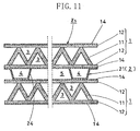
- the adsorption element 1 made up of three component members (i.e., an air ventilation passage forming member 11 formed from a bending plate member of fiber paper and a pair of side-plate members 12, 12 which are flat plate bodies of fiber paper and which are joined to one side and to the other side of the air ventilation passage forming member 11 , respectively), is shaped like a double-sided cardboard, and each side-plate member 12 is provided, on its exterior surface, with a respective separation sheet layer 14 .
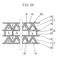
- the adsorption element 1 is made up of an air ventilation passage forming member 11 formed from a bending plate member of fiber paper on which an adsorbent is supported, and a pair of side-plate members 16, 16 which are joined to one side and to the other side of the air ventilation passage forming member 11 , respectively and which are formed from a sheet metal of aluminum etcetera or from a sheet resin, and each of the side-plate members 16, 16 directly supports on its interior surface an adsorbent as an adsorbent layer 18 .
- the side-plate members 16, 16 each directly support thereon an adsorbent.
- the distance between the adsorbent thus supported and the second air ventilation passage 4 on the side of the cooling element 2 becomes shorter, when compared with the case where the adsorbent is supported on the side-plate member 12 made of fiber paper, as in the dehumidification unit Z 4 of the fourth embodiment.
- the side-plate member 16 is formed from a sheet metal, there is produced a synergistic effect that the efficiency of transferring heat of adsorption generated in the adsorbent on the side of the adsorption element 1 towards the cooling element 1 is improved because such a sheet metal has a high heat transfer rate, and further improvement in the dehumidification capability of the dehumidification unit Z 6 is expected.
- dehumidification unit Z 7 formed in accordance with a seventh embodiment of the present invention.
- the dehumidification unit Z 7 is a result of the embodying of inventions as set forth in claim 1 and claim 3.
- the dehumidification unit Z 7 is configured basically the same as the dehumidification unit Z 5 of the fifth embodiment, with the exception of the way the adsorption element 1 is constructed.
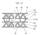
- the adsorption element 1 made up of three component members (i.e., an air ventilation passage forming member 11 formed from a bending plate member of fiber paper and a pair of side-plate members 12, 12 which are flat plate bodies of fiber paper and which are joined to one side and to the other side of the air ventilation passage forming member 11 , respectively), is shaped like a double-sided cardboard, and each side-plate member 12 is provided, on its exterior surface, with a respective separation sheet layer 14 .
- the adsorption element 1 is made up of an air ventilation passage forming member 11 formed from a bending plate member of fiber paper on which an adsorbent is supported, and a pair of side-plate members 16, 16 which are joined to one side and to the other side of the air ventilation passage forming member 11, respectively and which are formed from a sheet metal of aluminum etcetera or from a sheet resin, and each of the side-plate members 16, 16 directly supports on its interior surface an adsorbent as an adsorbent layer 18 .
- the side-plate members 16, 16 each directly support thereon an adsorbent.
- the distance between the adsorbent thus supported and the second air ventilation passage 4 on the side of the cooling element 2 becomes shorter, when compared with the case where the adsorbent is supported on the side-plate member 12 made of fiber paper, as in the dehumidification unit Z 5 of the fifth embodiment.
- the side-plate member 16 is formed from a sheet metal, there is produced a synergistic effect that the efficiency of transferring heat of adsorption generated in the adsorbent on the side of the adsorption element 1 towards the cooling element 1 is improved because such a sheet metal has a high heat transfer rate, and further improvement in the dehumidification capability of the dehumidification unit Z 7 is expected.
- dehumidification unit Z 8 formed in accordance with an eighth embodiment of the present invention.
- the dehumidification unit Z 8 is a result of the embodying of an invention as set forth in claim 2.
- the dehumidification unit Z 8 is configured basically the same as the dehumidification unit Z 6 of the sixth embodiment, with the exception of the way the cooling element 2 is constructed.
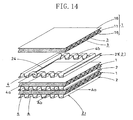
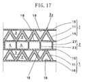
- the cooling element 2 is formed from the bending plate member 21 bent into a trapezoidal shape, and the second air ventilation passages 4, 4, ... defined in the cooling element 2 have a trapezoidal cross-sectional shape (i.e., an approximately rectangular cross-sectional shape), thereby to reduce the pressure loss of the cooling air (Ab).
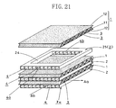
- the cooling element 2 is formed from an air ventilation passage forming member 21 made up of a plurality of band plate-like partition walls members 23, 23, ... vertically arranged in parallel with each other at predetermined intervals and the second air ventilation passage 4 formed between each partition wall member 23 has a rectangular cross-sectional shape, thereby to reduce the pressure loss of the cooling air (Ab).
- the cooling element 2 is formed from the air ventilation passage forming member 21 made up of the partition wall members 23, 23, ... arranged at predetermined intervals.
- the air ventilation passage forming member 21 is formed from a bending plate member.
- the cooling element 2 is formed from the air ventilation passage forming member 21 made up of the band plate-like partition wall members 23, 23, ... arranged vertically in parallel with each other at predetermined intervals, and the second air ventilation passage 4 formed between each partition wall member 23 has a rectangular cross-sectional shape, thereby to reduce the pressure loss of the cooling air (Ab).
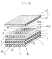
- the dehumidification unit Z 9 of the present embodiment two partition wall members 23 and 23 of all the partition wall members 23, 23, ... that are situated at both side ends of the dehumidification unit Z 9 are longer-size continuous members extending the full length of the adsorption element 1 .
- the rest of the partition wall members 23 are first shorter-size members 23a and second shorter-size members 23b .
- the first members 23a are arranged on one end side of the second air ventilation passages 4, 4, ... with respect to the passage direction, and the second members 23b are arranged on the other end side so that they are kept at a distance from each other.
- Rectangular passages defined between the first members 23a, 23a, ... serve as the entry portions 4a, 4a, ... of the second air ventilation passages 4
- rectangular passages defined between the second members 23b, 23b, ... serve as the exit portions 4b, 4b, ... of the second air ventilation passages 4 .
- a rectangular space facing the entry portions 4a, 4a, ... and the exit portions 4b, 4b, ..., i.e., the opening 24 is defined between the first members 23a, 23a, ... and the second members 23b, 23b, ....
- dehumidification unit Z 10 formed in accordance with a tenth embodiment of the present invention.
- the dehumidification unit Z 10 is a result of the embodying of inventions as set forth in claim 1 and claim 3.
- the dehumidification unit Z 10 is configured basically the same as the dehumidification unit Z 1 of the first embodiment, with the exception of the way the cooling element 2 is constructed.
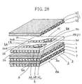
- the passage structure body 25 is formed from a frame-like thick plate. More specifically, the passage structure body 25 is constructed by forming, by punching or other technique, a rectangular opening through a planewise central portion of a single piece body in the form of a thick plate and in which a large number of rows of second air ventilation passages 4, 4, ... having a rectangular cross-sectional shape are arranged laterally. And, in the passage structure body 25 , by the formation of the opening 24 , two of the second air ventilation passages 4, 4, ..., located respectively at one end and at the other end in relation to the direction in which the rows of the second air ventilation passages 4, 4, ... are arranged, are continuous passages extending the full length of the cooling element 2 .
- the rest i.e., the remaining second air ventilation passages 4 located inside relative to the row arrangement direction
- the rest are in such a form that only entry portions 4a, 4a, ... located on one end side of the opening 24 and exit portions 4b, 4b, ... located on the other end side remain, wherein both the entry portions 4a, 4a, ... and the exit portions 4b, 4b, ... face the opening 24 .
- dehumidification unit Z 10 comprising alternate laminations of the cooling element 2 and the adsorption element 1 which are formed in accordance with the present embodiment:
- dehumidification unit Z 11 formed in accordance with an eleventh embodiment of the present invention.
- the dehumidification unit Z 11 is a result of the embodying of inventions as set forth in claim 1, claim 3, and claim 5.
- the dehumidification unit Z 11 is configured basically the same as the dehumidification unit Z 10 of the tenth embodiment, with the exception that they differ from each other partially in the configuration of the cooling element 2.
- the cooling element 2 is formed from a passage structure body 25 shaped like a thick plate frame in which a large number of second air ventilation passages 4, 4, ... are arranged in rows and whose planewise central portion is provided with an opening 24 .
- the cooling element 2 of the dehumidification unit Z 11 of the present embodiment is formed from a passage structure body 25 which is provided, at its passagewise, approximately central portion within the opening 24 , with an intermediate passage member 29 (which corresponds to "air stream regulating means X " as set forth in the claim) which is so disposed as to divide the opening 24 into two portions (i.e., a front portion and a rear portion), and the intermediate passage member 29 is provided with intermediate passages 4c, 4c, ... corresponding to the entry and exit portions 4a, 4a, ... and 4b, 4b, ... of the second air ventilation passages 4, 4, ... .
- the dehumidification unit Z 11 provided with the cooling element 2 of such construction, for example when the cooling air (Ab) flows, through the entry portions 4a, 4a, ... of the second air ventilation passages 4, 4, ... , into the opening 24 , there is the possibility that a flow deviation occurs because the cooling air (Ab) is allowed to freely flow within the opening 24 if the opening 24 is an undivided single volume portion.
- dehumidification unit Z 12 formed in accordance with a twelfth embodiment of the present invention.
- the dehumidification unit Z 12 is a result of the embodying of inventions as set forth in claim 1, claim 3, and claim 5.
- the intermediate passage member 29 is disposed in a passagewise intermediate area of the opening 24 so as to traverse it, and the cooling air (Ab) flowing in the side of the opening 24 is flow-rectified midway relative to the flow direction by the intermediate passage member 29 , thereby to inhibit the flow deviating of the cooling air (Ab) in the inside of the opening 24 .
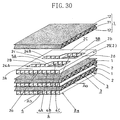
- a partition wall member 30 (which corresponds to "air stream regulating means X ") is so disposed as to divide the opening 24 side to side into two portions, i.e., a right side portion and a left side portion, whereby the flow of the cooling air (Ab) flowing into the opening 24 is split right and left. Consequently, this accomplishes not only improvement in the heat-liberation efficiency of heat of adsorption by the cooling air (Ab) in the area of the opening 24 but also further improvement in the dehumidification capability of the dehumidification unit Z 12 .
- dehumidification unit Z 13 formed in accordance with a thirteenth embodiment of the present invention.
- the dehumidification unit Z 13 is a result of the embodying of inventions as set forth in claim 1, claim 3, and claim 5, and has a configuration as a result of a combination of the dehumidification unit Z 11 of the eleventh embodiment and the dehumidification unit Z 12 of the twelfth embodiment.
- the intermediate passage member 29 is provided in the opening 24 in the dehumidification unit Z 11 of the eleventh embodiment and the partition wall member 30 is provided in the opening 24 in the dehumidification unit Z 12 of the twelfth embodiment, for the purpose of inhibiting the flow deviation of the cooling air (Ab) within the opening 24.
- the intermediate passage member 29 and the partition wall member 30 are provided within the opening 24.
- the cooling air (Ab) entering the inside of the opening 24 undergoes flow rectifying actions by the intermediate passage member 29 and flow dividing actions by the partition wall member 30 . This further ensures that the flow deviation of the cooling air (Ab) within the opening 24 is inhibited from occurring. As a result, the dehumidification unit Z 13 demonstrates its dehumidification capability at still higher levels.
- dehumidification unit Z 14 formed in accordance with a fourteenth embodiment of the present invention.
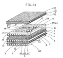
- the dehumidification unit Z 14 is a result of the embodying of inventions as set forth in claim 1, claim 3, claim 6, and claim 7, and is a developed example of the dehumidification unit Z 10 of the tenth embodiment.
- the opening 24 which is defined in a planewise central portion of the cooling element 2 is shaped like a rectangle corresponding to its outer shape (in other words all the entry portions 4a, 4a, ... situated on one end side of the opening 24 have the same length).
- the opening 24 is not shaped like a rectangle but is formed into an approximately trapezoidal shape so that one side of the trapezoid on the side of the entry portions 4a, 4a, ...
- the shape of the opening 24 is set such that the passage length of the entry portions 4a, 4a, ... situated on one end side of the opening 24 becomes gradually shorter with approach towards the downstream side from the upstream side of the first air ventilation passages 3, 3, ... (stated another way, the passage length becomes shorter the nearer to the downstream side of the first air ventilation passages 3, 3, ... ).
- the entry portions 4a, 4a, ... having different passage lengths together constitute a "flow rate regulating means Y " as set forth in the claim.
- the entry portions 4a, 4a, ... When the length of the entry portions 4a, 4a, ... is set as described above, the entry portions 4a, 4a, ... have progressively lower passage resistances the nearer to the downstream side of the first air ventilation passages 3, 3, ....
- the nearer an entry portion 4a is to the downstream side of the first air ventilation passages 3, 3, ...
- the lower is its passage resistance.
- the entry portions 4a, 4a, ... have progressively greater flow rates of the cooling air (Ab) flowing therethrough the nearer to the downstream side of the first air ventilation passages 3, 3, ... .
- the distribution of flow rates of the cooling air (Ab) within the opening 24 becomes greater the nearer to the downstream side of the first air ventilation passages 3, 3, ... .
- the entry portions 4a, 4a, ... have different passage lengths relative to the passage direction of the first air ventilation passages 3, 3, ... so that the flow deviation of the cooling air (Ab) is deliberately caused in the opening 24 . Because of the flow deviation of the cooling air (Ab), the following effects are provided.
- the temperature distribution of heat of adsorption on the side of the adsorption element 1 is observed.
- the heat of adsorption is high on the upstream side of the first air ventilation passages 3, 3, ... (i.e., on the inflow side of the to-be-processed air (Aa) to the adsorption element 1 ) but is low on the downstream side, corresponding to the degree of moisture adsorptive action. Consequently, the cooling air (Ab) evenly flows, through the second air ventilation passages 4, 4, ... on the side of the cooling element 2 extending in a direction orthogonal to the first air ventilation passages 3, 3, ..., into the cooling element 2 . Then, the cooling air (Ab) freely flows within the opening 24 without receiving any restrictive action.
- the dehumidification unit Z 15 is a result of the embodying of inventions as set forth in claim 8, claim 9, claim 10, and claim 17.
- the dehumidification unit Z 15 of the present embodiment is formed by sequentially alternately laminating a plurality of adsorption elements 1, 1, ... each provided with a large number of first air ventilation passages 3, 3, ... and a plurality of cooling elements 2, 2, ... each provided with a large number of second air ventilation passages 4, 4, ... in a 90-degree plane phase so that the first air ventilation passages 3, 3, ... are orthogonal to the second air ventilation passages 4, 4, ... when viewed from above.
- the dehumidification unit Z 15 of the present embodiment is such an integrally laminated structure.
- the adsorption element 1 of the dehumidification unit Z 15 is similar in construction to the adsorption element 1 of each of the previously described embodiments.
- the dehumidification unit Z 15 is characterized by the construction of the above-described cooling element 2 and by the operation/working effects based thereon. Accordingly, only the construction of the cooling element 2 will be described in detail.
- the construction of the adsorption element 1 and the basic operation/working effects of the dehumidification unit Z 15 prepared by a combination of the adsorption element 1 and the cooling element 2 are not described here (see the corresponding descriptions made in the foregoing embodiments).
- the cooling element 2 is a thick plate-like passage structure body 25 formed from a single-piece member.
- the passage structure body 25 is provided with second air ventilation passages 4, 4, ... which have a rectangular cross sectional shape and which are arranged laterally in a large number of rows.
- an upstream-side opening 24A and a downstream-side opening 24B are formed respectively at a first and a second position of the cooling element 2 by punching or other technique, so that these openings 24A and 24B pass completely through the cooling element 2 , wherein the first and second positions are spaced passagewise.
- the cooling element 2 has three different passage portions situated in a back-to-forth arrangement in the passage direction, namely an upstream-side passage portion 2A located at a passagewise upstreammost area 2a , an intermediate passage portion 2B located at an intermediate area, and a downstream-side passage portion 2C located at a downsreammost area 2b . Consequently, the second air ventilation passages 4, 4, ... are each made up of three different discontinuous flow paths facing each other across each opening 24A and 24B . More specifically, the second air ventilation passages 4, 4, ... each comprise a first flow path 4A formed in the upstream-side passage portion 2A , a second flow path 4B formed in the intermediate passage portion 2B , and a third flow path 4C formed in the downstream passage portion 2C .
- the intermediate passage portion 2B and the downstream-side passage portion 2C are each formed so as to have a two-stage stepped plane shape consisting of a narrow portion and a wide portion. More specifically, the passage portions 2B and 2C each have a two-stage stepped shape having a rear end edge and a front end edge. The rear end edge consists of a straight line approximately orthogonal to the passage direction. On the other hand, the front end edge extends linearly.
- each of the intermediate and downstream-side passage portions 2B and 2C (i.e., the dimension relative to the passage direction) is set such that an area situated nearer to a one side end 2c corresponding to the upstream side of the first air ventilation passages 3, 3, ... on the adsorption element's 1 side has a greater width dimension and an area situated nearer to a other side end 2d corresponding to the downstream side of the first air ventilation passages 3, 3, ... has a smaller width dimension, in the laminated state of the cooling element 2 and the adsorption element 1 .
- the dehumidification unit Z 15 prepared by a combination of the cooling element 2 of such configuration with the aforesaid adsorption element 1 provides the following operation and working effects.
- both opening surfaces of each of the openings 24A and 24B of the cooling element 2 are closed by two adsorption elements 1 adjacent to the cooling element 2 , thereby defining an upstream-side empty space 5A and a downstream-side empty space 5B .
- the first flow paths 4A, 4A, ... of the upstream-side passage portion 2A and the second flow paths 4B, 4B, ... of the intermediate passage portion 2B face the upstream-side empty space 5A .
- the second flow paths 4B, 4B, ... of the intermediate passage portion 2B and the third flow paths 4C, 4C, ... of the downstream-side passage portion 2C face the downstream-side empty space 5B .
- the cooling air (Ab) is introduced into the second air ventilation passages 4, 4, ... of the cooling element 2 from the side of the first flow paths 4A, 4A, .... Then, the cooling air (Ab) flows through the upstream-side empty space 5A , through the second flow paths 4B, 4B, ..., through the downstream-side empty portion 5B , and through the third flow paths 4C, 4C, ... in that order, thereby cooling the two adsorption elements 1 and 1 adjoining the cooling element 2 for liberation of heat of adsorption generated from the adsorption elements 1 and 1 .
- the openings 24A and 24B are provided.
- the passage length of the second air ventilation passages 4, 4, ... becomes shorter by an amount corresponding to the area occupied by the openings 24A and 24B , and the pressure loss of the cooling air (Ab) flowing through the second air ventilation passages 4, 4, ... is reduced correspondingly.
- the flow rate of the cooling air (Ab) flowing on the side of the cooling element 2 becomes higher by an amount corresponding to the reduction in pressure loss.
- the heat-liberation action of heat of adsorption by the cooling air (Ab) is accelerated and the total dehumidification capability of the dehumidification unit is improved.
- both the passage length of the first flow paths 4A, 4A, ... of the intermediate passage portion 2B and the passage length of the third flow paths 4C, 4C, ... of the downstream-side passage portion 2C are set as follows: the passage length of flow paths situated on the side nearer to the one side end 2c of the cooling element 2 is made longer and, on the other hand, the passage length of flow paths situated on the side nearer to the other side end 2d is made shorter. Thereby, there is created a difference in passage resistance between these areas. As a result of such a passage resistance difference, the cooling air (Ab) flows one-sidedly towards the other side end 2d at a lower level of passage resistance.
- the cooling element 2 its area on the side of the other side end 2d also effectively contributes to the cooling action of the adsorption element 1 (i.e., the heat-liberation action of heat of adsorption), and the effective heat-exchange region in the cooling element 2 is expanded correspondingly.
- the total dehumidification capability of the dehumidification unit Z 15 is improved to a further extent.
- the cooling air (Ab) is introduced to the second air ventilation passages 4, 4, ... of the cooling element 2 from the side of the first flow paths 4A, 4A, ...
- the heat of adsorption on the side of the adsorption element 1 has a temperature degradation in the passage direction of the first air ventilation passages 3, 3, .... Accordingly, there is a difference in temperature between streams of the cooling air (Ab) flowing through the second air ventilation passages 4, 4, ... of the cooling element 2 .
- the upstream-side empty space 5A and the downstream-side empty portion 5B are formed midway along the second air ventilation passages 4, 4, ....
- These cooling air streams are mixed together in the upstream-side empty space 5A and then flow towards the second flow paths 4B, 4B, ... as the cooling air (Ab) of approximately equal temperature.
- streams of the cooling air (Ab) having different temperatures after the passing-through of the second flow paths 4B, 4B, ... enter the inside of the downstream-side empty space 5B .
- These cooling air streams are mixed together in the downstream-side empty space 5B and then flow towards the third flow paths 4C, 4C, ... as the cooling air (Ab) of approximately equal temperature.
- the degree of temperature gradient in a direction orthogonal to the flow direction of the cooling air (Ab) i.e., the temperature gradient in the flow direction of the to-be-processed air (Aa) on the adsorption element's 1 side
- the whole area of the cooling element 2 serves as an effective area for heat-exchange and improvement in the dehumidification capability of the dehumidification unit Z 15 is expected.
- the cooling air (Ab) flowing through the empty spaces 5A and 5B is brought into direct contact with the adsorption element 1 .
- the empty spaces 5A and 5B i.e., the openings 24A and 24B
- the cooling air (Ab) flowing through the second air ventilation passages 4, 4, ... is brought into indirect contact with the adsorption element 1 with a passage wall lying therebetween, the efficiency of heat transfer between the adsorption element 1 and the cooling element 2 is more improved and the heat-liberation action of heat of adsorption by the cooling air (Ab) is accelerated.
- dehumidification unit Z 16 formed in accordance with a sixteenth embodiment of the present invention.
- the dehumidification unit Z 16 is a result of the embodying of inventions as set forth in claim 8, claim 9, claim 11, and claim 17 and is regarded as a modification example of the dehumidification unit Z 15 of the fifteenth embodiment.
- the dehumidification unit Z 16 of the present embodiment is characterized by the configuration of the cooling element 2.
- the dehumidification unit Z 16 of the sixteenth embodiment differs from the dehumidification unit Z 15 of the fifteenth embodiment as follows.
- dehumidification unit Z 15 which is characterized in that the upstream end edge of each of the intermediate and downstream-side passage portions 2B and 2C of the cooling element 2 is formed into a two-stage stepped shape, it is arranged in the dehumidification unit Z 16 of the sixteenth embodiment such that an approximately central portion of the upstream end edge of each of the intermediate and downstream-side passage portions 2B and 2C of the cooling element 2 is so formed as to slope linearly.
- both the passage resistance of the first flow paths 4A, 4A, ... of the intermediate passage portion 2B and the passage resistance of the third flow paths 4C, 4C, ... of the downstream-side passage portion 2C smoothly vary from a high resistance value region situated on the side nearer to the one side end 2c towards a low resistance value region situated one the side nearer to the other side end 2d in the cooling element 2 .
- the cooling element 2 of the present embodiment has an advantage over the cooling element 2 of the fifteenth embodiment in which the passage resistance varies discontinuously.
- only a predetermined area of the approximately central portion of the upstream end edge of each of the intermediate and downstream-side passage portions 2B and 2C is made to slope linearly.
- the present invention is not limited to such configuration.
- the upstream end edge may be made to slope throughout its entire area from one end side to the other end side.
- dehumidification unit Z 17 formed in accordance with a seventeenth embodiment of the present invention.
- the dehumidification unit Z 17 is a result of the embodying of inventions as set forth in claim 8, claim 9, claim 12, and claim 17 and is regarded as a modification example of the dehumidification unit Z 16 of the sixteenth embodiment.
- the approximately central portion of the upstream end edge of each of the intermediate and downstream-side passage portions 2B and 2C provided in the cooling element 2 is so formed as to slope linearly.
- the dehumidification unit Z 17 is configured differently from the dehumidification unit Z 16 of the sixteenth embodiment in that the approximately central portion of the upstream end edge of each of the intermediate and downstream-side passage portions 2B and 2C of the cooling element 2 is formed into a curved shape projecting outwardly.
- both the passage resistance of the first flow paths 4A, 4A, ... of the intermediate passage portion 2B and the passage resistance of the third flow paths 4C, 4C, ... of the downstream-side passage portion 2C smoothly vary from a high resistance value region situated on the side nearer to the one side end 2c to a low resistance value region situated on the side nearer to the other side end 2d in the cooling element 2 , as in the cooling element 2 of the sixteenth embodiment.
- the cooling element 2 of the present embodiment is advantageous.
- dehumidification unit Z 18 formed in accordance with an eighteenth embodiment of the present invention.
- the dehumidification unit Z 18 is a result of the embodying of inventions as set forth in claim 8, claim 9, claim 12, and claim 17.
- the dehumidification unit Z 18 is regarded as a modification example of the dehumidification unit Z 16 of the sixteenth embodiment.
- the approximately central portion of the upstream end edge of each of the intermediate and downstream-side passage portions 2B and 2C provided in the cooling element 2 is so formed as to slope linearly.
- the dehumidification unit Z 18 is configured differently from the dehumidification unit Z 16 in that the approximately central portion of the upstream end edge of each of the intermediate and downstream-side passage portions 2B and 2C of the cooling element 2 is formed into a curved shape projecting inwardly.
- both the passage resistance of the first flow paths 4A, 4A, ... of the intermediate passage portion 2B and the passage resistance of the third flow paths 4C, 4C, ... of the downstream-side passage portion 2C smoothly vary from a high resistance value region situated on the side nearer to the one side end 2c towards a low resistance value region situated on the side nearer to the other side end 2d in the cooling element 2 , as in the cooling element 2 of the sixteenth embodiment.
- the cooling element 2 of the present embodiment is advantageous.
- dehumidification unit Z 19 formed in accordance with a nineteenth embodiment of the present invention.
- the dehumidification unit Z 19 is a result of the embodying of inventions as set forth in claim 15 and claim 17.
- the dehumidification unit Z 19 is characterized by the construction of the cooling element 2.
- the dehumidification unit Z 19 of the present embodiment differs from the dehumidification units Z 15 -Z 18 of the fifteenth to eighteenth embodiments as follows: in the present embodiment, the intermediate passage portion 2B is formed so as to have approximately the same width from the one side end 2c to the other side end 2d of the cooling element 2 , in other words the second flow paths 4B, 4B, ... have approximately the same passage length. In addition, the passage direction of the second flow paths 4B, 4B, ... is made to slope so as to get closer to the other side end 2d of the cooling element 2 with approach towards the downstream side thereof.
- the intermediate passage portion 2B Since the passage direction of the second flow paths 4B, 4B, ... of the intermediate passage portion 2B is inclined as described above, the integral forming of the intermediate passage portion 2B with the upstream-side passage portion 2A and the downstream-side passage portion 2C (for example, by punching) becomes impossible to carry out. To cope with this, the intermediate passage portion 2B is preformed as a separated member from the passage structure body 25 constituting the cooling element 2 and, thereafter, is attached to the passage structure body 25 .
- the passage direction of the second flow paths 4B, 4B, ... of the intermediate passage portion 2B is inclined towards the other side end 2d of the cooling element 2 (i.e., towards the downstream side of the first air ventilation passages 3, 3, ... of the adsorption element 1).
- the cooling air (Ab) passes through the second flow paths 4B, 4B, ... of the intermediate passage 2B from the upstream-side empty space 5A and then flows towards the downstream-side empty space 5B , the cooling air (Ab) is forced to deviate towards the other side end 2d in the second flow paths 4B, 4B, ... , and the flow rate on the side of the other side end 2d becomes higher than that on the side of the one side end 2c .
- the deviating of the flow of the cooling air (Ab) is realized by making differences in passage resistance between the second air ventilation passages 4, 4, .... Unlike these embodiments, in the cooling element 2 of the present embodiment the deviating of the flow of the cooling air (Ab) is realized by inclining the passage direction of the second flow paths 4B, 4B, ... of the intermediate passage portion 2B .
- dehumidification unit Z 20 formed in accordance with a twentieth embodiment of the present invention.
- the dehumidification unit Z 20 is a result of the embodying of inventions as set forth in claim 8, claim 13, and claim 17.
- the dehumidification unit Z 20 is a modification example of the dehumidification unit Z 19 according to the nineteenth embodiment.
- the second flow paths 4B, 4B, ... provided in the intermediate passage portion 2B of the cooling element 2 have the same passage cross-sectional area and, in addition, the passage direction of the second flow paths 4B, 4B, ... is inclined towards the other side end 2d of the cooling element 2 .
- the integral forming of the intermediate passage portion 2B with the upstream-side passage portion 2A and the downstream-side passage portion 2C becomes impossible to carry out.
- the intermediate passage portion 2B is preformed as a separated member from the passage structure body 25 constituting the cooling element 2 and, thereafter, is attached to the passage structure body 25 .
- the same operation/working effects as obtained in the dehumidification units Z 15 -Z 18 of the fifteenth to eighteenth embodiments are obtained.
- dehumidification unit Z 21 formed in accordance with a twenty-first embodiment of the present invention.
- the dehumidification unit Z 21 is a result of the embodying of inventions as set forth in claim 8, claim 9, claim 10, claim 16, and claim 17.
- the dehumidification unit Z 21 has a construction formed by a combination of the construction of the cooling element 2 of the dehumidification unit Z 15 of the fifteenth embodiment and the construction of the cooling element 2 of the dehumidification unit Z 19 of the nineteenth embodiment. Therefore, the dehumidification unit Z 21 has both the characteristics of the cooling element 2 of the dehumidification unit Z 15 and the characteristics of the cooling element 2 of the dehumidification unit Z 19 .
- the cooling element 2 of the present embodiment is constructed as follows.
- the plane shape of each of the intermediate and downstream-side passage portions 2B and 2C is formed into a two-stage stepped shape.
- the passage length of the second and third flow paths 4B, 4B, ... and 4C, 4C, ... becomes longer on the side nearer to the one side end 2c but shorter on the side nearer to the other side end 2d in the cooling element 2 .
- the passage direction of the second and third flow paths 4B, 4B, ... and 4C, 4C, ... is made to slope so as to get gradually closer to the other side end 2d with approach towards the passage downstream side.
- the cooling air (Ab) flowing through the second air ventilation passages 4, 4, ... of the cooling element 2 undergoes: (i) forcible flow deviating actions resulting from inclining the passage direction of the second flow paths 4B, 4B, ... and the passage direction of the third flow paths 4C, 4C, ... , and (ii) flow deviating actions resulting from varying the passage resistance of the second flow paths 4B, 4B, ... and the passage resistance of the third flow paths 4C, 4C, ... by making differences in passage length between the second flow paths 4B, 4B, ... and between the third flow paths 4C, 4C, ...
- the dehumidification unit Z 21 demonstrates its dehumidification capability at higher levels.
- dehumidification unit Z 22 formed in accordance with a twenty-second embodiment of the present invention.
- the dehumidification unit Z 22 is a result of the embodying of inventions as set forth in claim 8, claim 9, claim 10, claim 14, and claim 17.
- the dehumidification unit Z 22 has a construction as a result of a combination of the construction of the cooling element 2 of the dehumidification unit Z 15 of the fifteenth embodiment and the construction of the cooling element 2 of the dehumidification unit Z 20 according to the twentieth embodiment. Therefore, the dehumidification unit Z 22 has both the characteristics of the cooling element 2 of the dehumidification unit Z 15 and the characteristics of the cooling element 2 of the dehumidification unit Z 20 .
- the cooling element 2 of the present embodiment is constructed as follows.
- the plane shape of each of the intermediate and downstream-side passage portions 2B and 2C is formed into a two-stage stepped shape.
- the passage length of the second and third flow paths 4B, 4B, ... and 4C, 4C, ... becomes longer on the side nearer to the one side end 2c but shorter on the side nearer to the other side end 2d in the cooling element 2 .
- the passage cross-sectional area of the second and third flow paths 4B, 4B, ... and 4C, 4C, ... is made smaller on the side nearer to the one side end 2c but larger on the side nearer to the other side end 2d of the cooling element 2 .
- the cooling air (Ab) flowing through the second air ventilation passages 4, 4, ... of the cooling element 2 undergoes (i) flow deviating actions resulting from varying the passage resistance of the second flow paths 4B, 4B, ... and the passage resistance of the third flow paths 4C, 4C, ... by making differences in passage length between the second flow paths 4B, 4B, ... and between the third flow paths 4C, 4C, ... and (ii) flow deviating actions resulting from varying the passage resistance of the second flow paths 4B, 4B, ... and the passage resistance of the third flow paths 4C, 4C, ...
- the dehumidification unit Z 22 demonstrates its dehumidification capability at higher levels.
- the present invention is useful for dehumidification units.
Landscapes
- Engineering & Computer Science (AREA)
- Chemical & Material Sciences (AREA)
- Mechanical Engineering (AREA)
- General Engineering & Computer Science (AREA)
- Analytical Chemistry (AREA)
- General Chemical & Material Sciences (AREA)
- Oil, Petroleum & Natural Gas (AREA)
- Chemical Kinetics & Catalysis (AREA)
- Combustion & Propulsion (AREA)
- Physics & Mathematics (AREA)
- Thermal Sciences (AREA)
- Drying Of Gases (AREA)
Applications Claiming Priority (1)
| Application Number | Priority Date | Filing Date | Title |
|---|---|---|---|
| PCT/JP2002/007509 WO2004010056A1 (ja) | 2002-07-24 | 2002-07-24 | 除湿素子 |
Publications (2)
| Publication Number | Publication Date |
|---|---|
| EP1553355A1 true EP1553355A1 (de) | 2005-07-13 |
| EP1553355A4 EP1553355A4 (de) | 2010-01-20 |
Family
ID=30490774
Family Applications (1)
| Application Number | Title | Priority Date | Filing Date |
|---|---|---|---|
| EP02749366A Withdrawn EP1553355A4 (de) | 2002-07-24 | 2002-07-24 | Entfeuchtungselement |
Country Status (5)
| Country | Link |
|---|---|
| US (1) | US7596961B2 (de) |
| EP (1) | EP1553355A4 (de) |
| CN (1) | CN100337064C (de) |
| AU (1) | AU2002320690B2 (de) |
| WO (1) | WO2004010056A1 (de) |
Cited By (1)
| Publication number | Priority date | Publication date | Assignee | Title |
|---|---|---|---|---|
| WO2018077481A1 (de) * | 2016-10-27 | 2018-05-03 | Linde Aktiengesellschaft | Plattenwärmetauscher |
Families Citing this family (13)
| Publication number | Priority date | Publication date | Assignee | Title |
|---|---|---|---|---|
| ATE502263T1 (de) * | 2002-07-22 | 2011-04-15 | Daikin Ind Ltd | Entfeuchtungselement und f r dieses verwendetes absorbierelement |
| JP5261865B2 (ja) * | 2005-07-26 | 2013-08-14 | パナソニック株式会社 | 除湿装置 |
| DE102006008786B4 (de) * | 2006-02-24 | 2008-01-17 | Fraunhofer-Gesellschaft zur Förderung der angewandten Forschung e.V. | Adsorptions-Wärmepumpe, Adsorptions-Kältemaschine und darin enthaltene Adsorberelemente auf Basis eines offenporigen wärmeleitenden Festkörpers |
| US8091868B2 (en) * | 2008-07-23 | 2012-01-10 | GM Global Technology Operations LLC | WVT design for reduced mass and improved sealing reliability |
| WO2010040819A1 (en) * | 2008-10-10 | 2010-04-15 | Gambro Lundia Ab | Heat exchanger and method for heat exchanging |
| JP2012516626A (ja) | 2009-01-27 | 2012-07-19 | トムソン ライセンシング | ビデオ符号化およびビデオ復号における変換の選択のための方法および装置 |
| WO2010129232A1 (en) | 2009-04-27 | 2010-11-11 | Dri-Eaz Products, Inc. | Systems and methods for operating and monitoring dehumidifiers |
| WO2011033624A1 (ja) * | 2009-09-16 | 2011-03-24 | 三菱電機株式会社 | 全熱交換素子 |
| CN102213558B (zh) * | 2011-04-13 | 2012-10-03 | 甘肃蓝科石化高新装备股份有限公司 | 一种纯逆流板壳式热交换器板束 |
| DE112012003607T5 (de) | 2011-08-31 | 2014-05-15 | Dri-Eaz Products, Inc. | Entfeuchter mit einer verbesserten Fluidhandhabung sowie assoziierte Verfahren zur Verwendung und Herstellung |
| AU2012323876B2 (en) * | 2011-10-14 | 2017-07-13 | Legend Brands, Inc. | Dehumidifiers having improved heat exchange blocks and associated methods of use and manufacture |
| US9513067B2 (en) * | 2012-09-26 | 2016-12-06 | Sonoco Development, Inc. | Convection based temperature assured packaging system |
| USD731632S1 (en) | 2012-12-04 | 2015-06-09 | Dri-Eaz Products, Inc. | Compact dehumidifier |
Family Cites Families (13)
| Publication number | Priority date | Publication date | Assignee | Title |
|---|---|---|---|---|
| SE333631B (de) * | 1969-07-17 | 1971-03-22 | C Munters | |
| JPS5753304Y2 (de) * | 1978-09-06 | 1982-11-18 | ||
| JPS56132471U (de) * | 1980-03-07 | 1981-10-07 | ||
| US4854129A (en) * | 1987-06-11 | 1989-08-08 | Hickley Pieter | Cooling process and apparatus |
| US5226298A (en) * | 1991-01-16 | 1993-07-13 | Matsushita Electric Industrial Co., Ltd. | Thermoelectric air conditioner with absorbent heat exchanger surfaces |
| US5212956A (en) * | 1991-01-18 | 1993-05-25 | Ari-Tec Marketing, Inc. | Method and apparatus for gas cooling |
| US5547019A (en) * | 1994-10-28 | 1996-08-20 | Iacullo; Robert S. | Thermoelectric intercooler cooling turbocharged air |
| JPH08313186A (ja) | 1995-05-24 | 1996-11-29 | Mitsubishi Electric Corp | 熱交換器 |
| CA2283089C (en) * | 1999-05-10 | 2004-05-25 | Mitsubishi Denki Kabushiki Kaisha | Heat exchanger and method for preparing it |
| JP2001062242A (ja) * | 1999-08-30 | 2001-03-13 | Seibu Giken Co Ltd | 除湿装置 |
| US6361588B1 (en) * | 1999-12-22 | 2002-03-26 | Jose Moratalla | Selective permeability energy recovery device |
| US6705096B2 (en) * | 2000-09-27 | 2004-03-16 | Idalex Technologies, Inc. | Method and plate apparatus for dew point evaporative cooler using a trough wetting system |
| ATE502263T1 (de) * | 2002-07-22 | 2011-04-15 | Daikin Ind Ltd | Entfeuchtungselement und f r dieses verwendetes absorbierelement |
-
2002
- 2002-07-24 AU AU2002320690A patent/AU2002320690B2/en not_active Ceased
- 2002-07-24 US US10/521,959 patent/US7596961B2/en not_active Expired - Fee Related
- 2002-07-24 EP EP02749366A patent/EP1553355A4/de not_active Withdrawn
- 2002-07-24 CN CNB028293649A patent/CN100337064C/zh not_active Expired - Fee Related
- 2002-07-24 WO PCT/JP2002/007509 patent/WO2004010056A1/ja not_active Ceased
Cited By (1)
| Publication number | Priority date | Publication date | Assignee | Title |
|---|---|---|---|---|
| WO2018077481A1 (de) * | 2016-10-27 | 2018-05-03 | Linde Aktiengesellschaft | Plattenwärmetauscher |
Also Published As
| Publication number | Publication date |
|---|---|
| AU2002320690A1 (en) | 2004-02-09 |
| CN100337064C (zh) | 2007-09-12 |
| EP1553355A4 (de) | 2010-01-20 |
| US7596961B2 (en) | 2009-10-06 |
| CN1639515A (zh) | 2005-07-13 |
| AU2002320690B2 (en) | 2007-03-29 |
| WO2004010056A1 (ja) | 2004-01-29 |
| US20050235673A1 (en) | 2005-10-27 |
Similar Documents
| Publication | Publication Date | Title |
|---|---|---|
| US7596961B2 (en) | Dehumidification element | |
| US7066243B2 (en) | Evaporator, manufacturing method of the same, header for evaporator and refrigeration system | |
| US7470311B2 (en) | Dehumidification unit and adsorption element for use in such a dehumidification unit | |
| AU2002304250A1 (en) | Evaporator, manufacturing method of the same, header for evaporator and refrigeration system | |
| JP3861639B2 (ja) | 除湿素子 | |
| JPH0739895B2 (ja) | 冷媒蒸発器 | |
| JP3840571B2 (ja) | 除湿素子 | |
| JP2004155248A (ja) | 自動車用空調装置およびその製造方法 | |
| JPS62200193A (ja) | 積層型蒸発器 | |
| JP3835223B2 (ja) | 冷却吸着素子 | |
| JP3632128B2 (ja) | 吸着用素子及びこれを備えた除湿素子 | |
| JPH0560481A (ja) | 熱交換器 | |
| JP3045137B2 (ja) | 熱交換エレメント | |
| JP7428421B1 (ja) | 熱交換素子 | |
| CN223472460U (zh) | 散热翅片模组以及相关计算机系统 | |
| JP7428420B1 (ja) | 熱交換素子 | |
| JP2003144834A (ja) | 冷却吸着素子 | |
| JPH064227Y2 (ja) | 積層型熱交換器 | |
| JP2001174172A (ja) | 熱交換素子 | |
| JPH0222319B2 (de) | ||
| JP2005083653A (ja) | 冷媒蒸発器 | |
| JP3610788B2 (ja) | 熱交換エレメントおよび空気調和装置 | |
| JPS62178895A (ja) | 伝熱管 | |
| JPH0713552B2 (ja) | 冷蔵庫用蒸発器 | |
| JP2003071237A (ja) | 冷却用素子及びこれを備えた除湿素子 |
Legal Events
| Date | Code | Title | Description |
|---|---|---|---|
| PUAI | Public reference made under article 153(3) epc to a published international application that has entered the european phase |
Free format text: ORIGINAL CODE: 0009012 |
|
| 17P | Request for examination filed |
Effective date: 20050211 |
|
| AK | Designated contracting states |
Kind code of ref document: A1 Designated state(s): AT BE BG CH CY CZ DE DK EE ES FI FR GB GR IE IT LI LU MC NL PT SE SK TR |
|
| AX | Request for extension of the european patent |
Extension state: AL LT LV MK RO SI |
|
| DAX | Request for extension of the european patent (deleted) | ||
| A4 | Supplementary search report drawn up and despatched |
Effective date: 20091218 |
|
| 17Q | First examination report despatched |
Effective date: 20100331 |
|
| STAA | Information on the status of an ep patent application or granted ep patent |
Free format text: STATUS: THE APPLICATION IS DEEMED TO BE WITHDRAWN |
|
| 18D | Application deemed to be withdrawn |
Effective date: 20100811 |