EP1554210B1 - Rail de guidage pour monte-escalier - Google Patents
Rail de guidage pour monte-escalier Download PDFInfo
- Publication number
- EP1554210B1 EP1554210B1 EP03757725A EP03757725A EP1554210B1 EP 1554210 B1 EP1554210 B1 EP 1554210B1 EP 03757725 A EP03757725 A EP 03757725A EP 03757725 A EP03757725 A EP 03757725A EP 1554210 B1 EP1554210 B1 EP 1554210B1
- Authority
- EP
- European Patent Office
- Prior art keywords
- guide rail
- carrier
- staircase
- guide
- members
- Prior art date
- Legal status (The legal status is an assumption and is not a legal conclusion. Google has not performed a legal analysis and makes no representation as to the accuracy of the status listed.)
- Expired - Lifetime
Links
- XAGFODPZIPBFFR-UHFFFAOYSA-N aluminium Chemical compound [Al] XAGFODPZIPBFFR-UHFFFAOYSA-N 0.000 claims description 7
- 229910052782 aluminium Inorganic materials 0.000 claims description 7
- 239000004411 aluminium Substances 0.000 claims description 7
- 239000004020 conductor Substances 0.000 claims description 7
- 238000004381 surface treatment Methods 0.000 claims description 3
- 238000006073 displacement reaction Methods 0.000 claims description 2
- 230000007246 mechanism Effects 0.000 description 6
- 230000008859 change Effects 0.000 description 5
- 230000003019 stabilising effect Effects 0.000 description 4
- 239000000463 material Substances 0.000 description 3
- 230000005540 biological transmission Effects 0.000 description 2
- 239000011248 coating agent Substances 0.000 description 2
- 238000000576 coating method Methods 0.000 description 2
- 239000004519 grease Substances 0.000 description 2
- 230000000717 retained effect Effects 0.000 description 2
- 239000004677 Nylon Substances 0.000 description 1
- 229910000831 Steel Inorganic materials 0.000 description 1
- 239000004809 Teflon Substances 0.000 description 1
- 229920006362 Teflon® Polymers 0.000 description 1
- 230000004308 accommodation Effects 0.000 description 1
- 230000009471 action Effects 0.000 description 1
- 238000005452 bending Methods 0.000 description 1
- 230000008901 benefit Effects 0.000 description 1
- 238000004040 coloring Methods 0.000 description 1
- 230000008878 coupling Effects 0.000 description 1
- 238000010168 coupling process Methods 0.000 description 1
- 238000005859 coupling reaction Methods 0.000 description 1
- 230000000694 effects Effects 0.000 description 1
- 238000001125 extrusion Methods 0.000 description 1
- 239000002783 friction material Substances 0.000 description 1
- 238000007373 indentation Methods 0.000 description 1
- 238000009434 installation Methods 0.000 description 1
- 238000005461 lubrication Methods 0.000 description 1
- 238000005259 measurement Methods 0.000 description 1
- 238000000034 method Methods 0.000 description 1
- 229920001778 nylon Polymers 0.000 description 1
- 229920000642 polymer Polymers 0.000 description 1
- 230000008569 process Effects 0.000 description 1
- 230000001681 protective effect Effects 0.000 description 1
- 238000007789 sealing Methods 0.000 description 1
- 239000010959 steel Substances 0.000 description 1
- 239000002344 surface layer Substances 0.000 description 1
- 239000000725 suspension Substances 0.000 description 1
Images


Classifications
-
- B—PERFORMING OPERATIONS; TRANSPORTING
- B66—HOISTING; LIFTING; HAULING
- B66B—ELEVATORS; ESCALATORS OR MOVING WALKWAYS
- B66B9/00—Kinds or types of lifts in, or associated with, buildings or other structures
- B66B9/06—Kinds or types of lifts in, or associated with, buildings or other structures inclined, e.g. serving blast furnaces
- B66B9/08—Kinds or types of lifts in, or associated with, buildings or other structures inclined, e.g. serving blast furnaces associated with stairways, e.g. for transporting disabled persons
- B66B9/0846—Guide rail
Definitions
- the present invention relates to a staircase lift for transporting a disabled person between floors according to the preamble of claim 1.
- Staircase lifts of this kind are used to carry disabled persons in wheelchairs or elderly people between floors by means of a stairway.
- the staircase lift can be mounted on the sidewall or columns of stairways used both indoors and outdoors.
- the staircase lift includes a moveable frame displaced along a fixedly mounted guide rail on the side of the stairway. This type of staircase lift is driven by a rack and pinion drive whereby relatively steep staircases and a relatively heavy weight may be displaced in the lift.
- a second support rail is provided for stability of the carter frame during movement of the lift.
- staircase lifts are used; a so-called platform lift where the carrier frame is provided with drive means and a platform for a wheelchair, and where the platform may be folded up when not in use; or a so-called seat lift where the frame is provided with a foldable seat whereby a chair is provided and accordingly a seating facility for the person to be transported on the lift
- a so-called platform lift where the carrier frame is provided with drive means and a platform for a wheelchair, and where the platform may be folded up when not in use
- seat lift where the frame is provided with a foldable seat whereby a chair is provided and accordingly a seating facility for the person to be transported on the lift
- US-A-5,967,265 discloses a staircase lift for transporting an individual passenger with a carriage moveable along a rail and a drive mechanism coupled to the carriage.
- the lift is well adapted to cooperate with level or curved or inclined guiding rails, e.g. a substantially level curved section or an inclined straight section.
- level or curved or inclined guiding rails e.g. a substantially level curved section or an inclined straight section.
- this lift will not be able to function due to the fixed moveable frame/guiding rail relationship.
- US-A-5,709,154 discloses a monorail access system for making a boat handicapped accessible.
- the lift includes a battery powered chair which is suspended from the rail.
- staircase lifts with such solutions are known from e.g. WO95/29867 and EP-A-1 053 968 .
- these solutions overcome the problem of keeping the frame in a vertical position during changes in the slope, the pinion is displaced in the engagement with the rack if the guide rail is curved.
- these known staircase lifts are only suitable for straight stairways, as the risk of damaging the drive mechanism when entering a curved section of the stairway is too high which results in an unacceptable level of safety.
- the drive mechanism in a staircase lift is loaded with the entire weight of the platform, which means that even slight displacements may have devastating effects.
- the guide rail system takes up a lot of space and has a rough and greasy surface pointing towards the staircase whereby pieces of clothing on persons transported in the lift or other people walking on the staircase may be caught or otherwise damaged, e.g. due to oil or grease on the track or even on the steps of the stairway.
- a staircase lift of the initially mentioned kind is provided, with the features of the characterizing portion of claim 1, as well as the features of claim 16.
- a staircase lift By a staircase lift according to the invention, the objects have been achieved.
- the drive mechanism including the guide and carrier members By positioning the drive mechanism including the guide and carrier members inside the guide rail, a smooth exterior surface of the guide rail is maintained.
- the problem with the collection and deposit of dirt on the guide rail banister is eliminated.
- the guide rail may be designed with smooth exterior surface which is not engaged by carrier members and the like. This means that the guide rail may be provided with a surface coating or treatment chosen in order to fulfilling the requirements concerning its secondary function as a banister in the staircase.
- the drive means comprises a first and second set of guide members pivotally arranged one behind the other on each side of the pinion drive wheel in the frame.
- a staircase lift according to the invention is suitable for installation in a staircase with variable slope and bends, such as a staircase with one or more intermediate plateaux comprising a discrete guide rail with curved portions.
- a compact drive means i.e. with a vertically oriented pinion, is provided which ensures that the pinion is kept centred in the rack in the guide rail and that the moveable frame is provided with sufficient stability also when entering into a bent portion, running in the bent portion and exiting the bent portion.
- a satisfactory solution is provided making a side rail guided staircase lift suitable for running along a curved track in a stabile and smooth manner while also offering a comfortable and smooth ride in a signifying way for the disabled persons using the lift.
- the carrier support means include at least one carrier member arranged substantially above the pinion drive wheel in a traction plane and with an axis of rotation which is substantially perpendicular to the direction of travel, and wherein each of the first and second set of guiding means include an essentially vertically arranged carrier member and a top and bottom guide member having a rotary axis substantially perpendicular to that of the carrier member.
- the vertical rotation axis of the carrier frame when running along a bent portion of the guide rail, is well determined and it is ensured that the vertical rotation axis coincides with the radial axis of symmetry of the tooth or teeth of the pinion meshed with the rack.
- the pivotally arranged first and second guiding means each include a movement control lever with a first end where at least one set of idle rollers is mounted, a second end at which point the first and second movement control levers are joined to each other by a universal joint, said universal joint being substantially in the traction plane.
- a compact centring and stabilising system is provided.
- the movement control levers are preferably pivotally mounted to the carrier frame at an equal distance from the universal joint on each side thereof.
- the geometry of the movement control is similar irrespective of the direction of movement.
- the guide rail has a generally reverse U-shape comprising a lower rail opening beside the rack of the guide rail. Moreover, the guide rail in its internal cavity is provided with at least one support surface essentially perpendicular to the traction plane for receiving the carrier members and a number of substantially vertical support surfaces for receiving engagement with the guide members.
- the movement control levers as they are provided with a fork-like or T-like shape, are particularly compact
- the carrier member positions the carrier frame relative to the horizontal support surface inside the cavity of the guide rail.
- the guide members ensure an accurate position of the frame by engaging the vertical support surfaces inside the rail whereby a particularly firm locking grip inside the guide rail is established preventing the carrier frame from pivoting.
- the upper and lower rollers co-operate to constrain the movement of the frame to movements in the directions along the guide rail.
- the teeth of the pinion wheel are substantially circular in the cross-section and the rack of the guide rail displays a row of correspondingly shaped circular holes.
- the pinion is allowed to rotate whilst being intermeshed with the toothed rack.
- at least one section of the guide rail may be curved in one or more planes.
- the carrier member and/or the guiding members are made up by slide shoes, sliding on the internal support surfaces of the guide rail.
- the guide rollers are provided as guiding members. Since the guiding members are to provide guidance of the carrier frame by engaging associated surfaces on the guide rail, which are internal surfaces, the use of sliding members, such as slide shoes these internal support surfaces may be swept clean as the guiding member is sliding across the surface.
- the sliding shoes may be made up by or at least provided with a surface layer of low-friction material, such as Teflon or the like.
- a staircase lift according to the invention may further include a supporting guide rail mounted parallel to the first guide rail for assisting the first guide rail in carrying the load and stabilising the load-carrying frame.
- the carrier frame is provided with a platform adapted to accommodate a wheelchair.
- the handicapped person may place the wheelchair on the platform, either by himself or with the assistance of an assistant, and operate the lift for being transported up or down the stairs.
- the carrier frame is provided with a foldable seat for aiding disabled persons or weakened persons otherwise not able to climb the stairs.
- the staircase lift is preferably provided with the required control and operating system as well as an emergency safety lock of the carrier frame to the rack. In this way, it is ensured that the frame will be held still, even if both the driving means and the carrying means collapse.
- a guide rail including a generally reverse U-shape comprising a bottom rail opening beside a groove for receiving a rack for cooperating with a pinion drive wheel, and wherein the guide rail in its internal cavity is provided with at least two support surfaces having an orientation different from, preferably substantially perpendicular to the traction plane for receiving one or more carrier members and a number of substantially vertical support surfaces for receiving engagement with a number of guide members.
- the carrier support means may be suspended in the guide rail and being retained therein since the two support surfaces absorb the moment of the slidable connection between the guide rail and the carrier frame.
- the guide rail is provided with side mounting means.
- the guide rail is simple to use as a banister.
- the guide rail is provided with an upper guide member support surface facing towards the side mounting means and a second lower guide member support surface facing away from the side mounting means, and wherein the lateral distance between the side mounting means and the carrier member support surface is smaller than the distance between the side mounting means and the lower guide member support surface which again is smaller than the distance between the side mounting means and the upper guide member support surface.
- the carrier guide members are shiftably arranged inside the cavity and are retained therein due to this geometry of the cavity.
- the guide rail may preferably be provided with one or more power conductor rails inside the cavity of the profile and the carrier frame is accordingly provided with contact members, such as contact brushes, contact carbons or the like.
- contact members such as contact brushes, contact carbons or the like.
- the conductor rails may not only be used for main power supply but additional conductor rails may be provided inside the cavity of the guide rail for power supply to and electronic transmission to and from a control panel on the carrier frame, which may be operated by the user, i.e. the person on the lift.
- the guide rail is preferably made of an extruded aluminium profile.
- an aluminium extrusion process By using an aluminium extrusion process, a profile having a quite complex but still accurate internal geometry may be obtained.
- Another advantage of using an aluminium profile and the internal drive system is that the aluminium profile may be anodised or in other ways coated or provided with a surface treatment.
- Such surface treatment could be a protective and/or decorative coating or treatment, e.g. a colouring of the outside of the guide rail so that the guide rail which also functions as a banister may be provided in a desired colour.
- a staircase with a staircase lift is shown.
- the staircase lift is mounted on the side of the stairway, on a sidewall or a separate frame structure.
- the staircase lift includes a fixed part and a moveable part.
- the fixed part comprises a first guide rail 2 and a second guide rail 3.
- the two guide rails 2, 3, are mounted in parallel with one above the other on the side.
- the guide rails 2, 3, or at least the first guide rail 2, is/are made of a profile which functions as a banister for the stairway.
- the guide rails 2, 3 follow the staircase as it changes direction. This results in a bent or curved portion 2a of the guide rail 2, 3.
- This curvature may be a result of a change in slope of the staircase and/or a change in direction, i.e. the curvature may be in a horizontal or a vertical direction or both.
- the first guide rail 2, i.e. the top one is provided with a rack for a geared engagement with driving means 6 of a moveable carrier frame 4 for displacing the carrier frame 4 along the guide rails 2, 3.
- the second guide rail 3 functions as a support for the moveable frame 4 displaced along the guide rails 2, 3.
- the carrier frame 4 may be provided with stabilising means for keeping the frame 4 in a vertical position and the platform 5 in a horizontal orientation.
- the driving means 6 of the carrier frame 4 may comprise a motor 63 driving the pinions 7 through a top gear box 61 and a lower gear box 62 associated with the first and second guide rail 2, 3, respectively.
- the motor is driving the gear boxes 61, 62 through a coupling section 62.
- the gear boxes 61, 62 which are provided with identical transmission ration, are preferably driven by the same drive axis 64 so as to ensure that the lift is not tilted during a run.
- the common drive axis 64 may extend beyond the gearbox housing where it may be provided with a manually drivable emergency wheel.
- the moveable frame 4 includes a platform 5 for accommodating a disabled person in a wheelchair.
- a foldable seat may be provided for an assistant to the person in the wheelchair or for transporting an elderly or otherwise weakened person up or down the staircase, see fig. 13 .
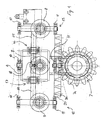
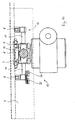
- FIG. 3 a first embodiment of the invention is shown.
- a cross-section of the guide rail 2 having a sub-frame 9 of the carrier frame 4 provided therein.
- a pinion wheel 7 engages a rack 20 provided on the lowermost section of the guide rail 2.
- the pinion wheel 7 is provided with teeth 7a shaped in the geometrically correct curved form in the radial direction of the pinion 7, but provided with a circular cross-section.
- the rack 20 is formed in a strip of material, preferably nylon or similar polymeric material, extending along the underside of the guide rail with a row of circular holes 7b.
- the pinion 7 is preferably made of steel.
- the guide rail 2 is intended for use as a banister, the persons using the banister of the staircase might come into contact with the rack as they support themselves by means of the banister.
- a polymer-based material for the rack By using a polymer-based material for the rack, the necessity for lubrication of the drive system is avoided which is advantageous as this, in turn, means that no grease or oil is deposited or present on the guide rail rack.
- the moveable frame 4 is driven along the guide rail 2 by the rack and pinion type drive, where the frame 4 is self-propelled as the pinion 7 is driven by an electric motor (not shown) powered by a rechargeable battery package (also not shown).
- the pinion 7 engages the rack 20 on the underside of the guide rail 2.
- the guide rail 2 is a hollow profile, preferably an aluminium profile provided with internal support surfaces 21, 22, 23, 24, 25 inside its cavity.
- a carrier member 8 and a top guide member 10 and a lower guide member 11 are provided on the sub-frame 9, power supply rails 26 may preferably be provided cooperating with brushes 27 or similar sliding electrical connection means for providing power supply to the electric drive motor on the carrier frame 4.
- a carrier member 8 is positioned to engage a support surface 25 immediately above the rack 20 and the pinion 7.
- the carrier member 8 rest on the internal support surface 25 of the cavity of the guide rail 2 and carry the weight of the frame and its load - possibly together with co-operating carrier members engaging the lower second guide rail 3 and carrier members on the guiding means 12, 13.
- the pinion wheel 7 and the carrier member 8 are accommodated in a sub-frame 9 to which the rest of the moveable frame 4 is pivotally mounted.
- First and second sets of guiding means 12, 13, respectively, are arranged on each side - seen in the direction of travel - of the pinion wheel 7 and the carrier member 8 arranged on the sub-frame 9 immediately above the pinion wheel 7 engaging the inside support surface 25.
- a top and a lower guide member 10, 11 are arranged inside the cavity, so that these guide members 10, 11 engages the vertically orientated support surfaces 21, 22 and 23, 24, respectively.
- the guiding means 12, 13 each include top and bottom guide members 10, 11, which are mounted on movement control levers 14 and 15 with a rotary plane generally perpendicular to the plane in which the frame moves.
- Each of the movement control levers 14 and 15 are fork-like or T-like in shape and carry the top guide members 10 and the lower guide member 11 on each of the fork-fingers.
- the levers 14, 15 are joined together by a universal joint 18 positioned substantially in the central plane of the set of carrier member 8 and the pinion 7.
- the levers 14 and 15 are pivotally mounted to the sub-frame in swivel joint bearings 16 and 17, respectively.
- the levers are provided with a certain length so that the guide members 10, 11 of the first movement lever 15 and the guiding members 10, 11 of the second lever 14 are disposed at a suitable distance from the carrier members 8 and the pinion 7 arranged in the middle of the drive means 6.
- the guiding means 12, 13 also include a carrier member 8 positioned between the top and lower guide members 10, 11 in a similar arrangement as the drive means 6. These carrier members 8 of the guiding means 12, 13 also engage the generally horizontally provided internal support surface 24.
- the guide members 10, 11 and the carrier members 8 are roller members which roll on the respective internal support surfaces.
- slide members may also be utilised instead of or in combination with the rollers.
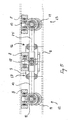
- FIG. 8 to 12 a second embodiment using slide shoes as the carrier member 8 and the guide members 10, 11 is shown.
- the movement control levers 14 and 15 are bent out of the centring plane and mounted to the sub-frame 9 in a plane parallel to the centring plane at a certain distance between the two parallel planes. In this plane, the universal joint 18 is also disposed.
- the first set of guide members 10, 11, the carrier members and the driving pinion wheel 7 and the second set of guide members 12, 13 are linked to each other in such a way that the sub-frame, and thereby the pinion and the set of carrier members 8, is automatically placed with an inclination corresponding to the tangential orientation of the section of the track in which it is present due to the linkage between the sets of guide members 10, 11; 12, 13 in front of and behind the drive pinion 7.
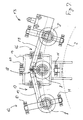
- a drive system according to the invention is shown in action.
- the guide rail 2 is bent, e.g. due to a change in slope of the staircase.
- the first set of guide members 10, 11 is lifted upwards, causing the universal joint 18 downwards due to the movement control lever 15 which is pivotally mounted in the swivel joint 16.
- the second movement control lever 14 is loaded.
- a similar situation of movement is illustrated in relation to a turn, e.g. as the staircase lift is mounted in a swinging staircase, or the guide rail 2 follows a corner of a staircase.
- the first set of rollers 10 is moved sideways towards the direction of the turn, e.g. to the left, causing the first movement control lever 15 to pivot in the swivel joint 16 and move the universal joint 18 outwards in the turn which forces the second movement control lever 14 to move the sub-frame 9 outwards due to the swivel joint connection of the second movement lever 14 to the sub-frame 9.
- the tooth or teeth 7a of the pinion 7 engaging the rack is/are kept in alignment in the rack 20, also during a change in the direction of travel of the frame.
- the components of the drive means 6 are preferably mirrored so that the geometry and the physical characteristics of their movement are the same irrespective of the direction of movement of the moveable frame in the staircase lift.
- Micro switches or other types of distance measurement equipment may be provided at the extreme positions of movements of the vertical direction 18b of the universal joint 18 in order to provide a control signal for a control system to automatically adjusting the carrier frames relative position to the sub-frame 9 as the staircase lift runs through a change in the slope.
- a control system to automatically adjusting the carrier frames relative position to the sub-frame 9 as the staircase lift runs through a change in the slope.
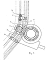
- a second embodiment of the invention is shown.
- This embodiment is particularly advantageous as the position of slide support surfaces 22, 24 and 25.
- the sub-frame 9 is suspended from the guide rail 2, which is mounted by the mounting means 28.
- the upper slide shoe 10 engages the vertical support surface 22 and the lower slide shoe 11 engages the lower vertical support surface 24, whereas the carrier slide shoe 8 engages the horizontal support surface 25.
- the support surfaces 22, 24 and 25 are integrally formed on the inside cavity of the generally U-shaped guide rail 2 (see fig. 14 ).
- the guide rail profile 2 provided with a cavity 29 in which the support surfaces are provided.
- side mounting receiving means 35 are integrally provided.
- the outside surface is otherwise provided with a generally smooth surface making the guide rail profile 2 a proper staircase banister.
- the upper guide member support surface 22 is provided in the uppermost outer portion of the profile 2
- the lower guide member support surface 24 is provided in the lower innermost section close to the side mounting means and the profile opening 33.
- the horizontal carrier member support surface 25 is provided in the cavity 29 in between the lower guide support surface and the side mounting receiving means 35 which are formed on the outside of this profile wall portion.
- the guide rail profile according to this embodiment is thus particularly advantageous for accommodating the internally arranged carrier support means for driving the staircase lift.
- the profile cavity 29 is provided with indentations 31, 32 for the accommodation of power supply rails 27 which cooperate with associated brushes or similar power connecting means 26 on the sub-frame 9.
- a set of covering brushes or sealing lips 34 may be provided in order to prevent dirt from entering into the profile cavity 29.
- a track 30 for accommodating the toothed rack 20, said track being integrally formed in the profile 2 just below the horizontal support surface 25.
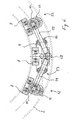
- the carrier support means according to the second embodiment of the invention is shown.
- the first and second guiding means 12, 13 are arranged with a cooperating functional relationship similar to the relationship described in figures 4 and 5 .
- each extreme end of the guiding means 12, 13 may be provided with an end stop sensor 36.
- an end stop sensor 36 is shown only at the second guiding means 13.
- the power connecting slide means 26 may be provided at one of the guiding means 13, as shown in fig. 9 to 12 or at both guiding means 12, 13 (not shown).
- Figures 11 and 12 show the carrier support means running through bends in either a horizontal or a vertical plane corresponding to the figures 6 and 7 , respectively.
- FIG 13 another embodiment of the invention is shown, as the staircase lift according to the invention is designed as a seat type lift.
- the staircase lift according to the invention is designed as a seat type lift.
- only one guide rail is used.
- the guide support means in this embodiment are basically the same as for the platform lift, but may be slightly altered as no second guide rail is provided, e.g. additionally, the lift may be provided with vertical stabilising means ensuring the desired substantially horizontal orientation of the seat is maintained.
Landscapes
- Engineering & Computer Science (AREA)
- Mechanical Engineering (AREA)
- Transportation (AREA)
- Automation & Control Theory (AREA)
- Structural Engineering (AREA)
- Types And Forms Of Lifts (AREA)
- Train Traffic Observation, Control, And Security (AREA)
- Steps, Ramps, And Handrails (AREA)
Claims (23)
- Monte-escalier destiné à transporter une personne handicapée entre des étages, comportant- au moins un rail de guidage (2, 3) s'étendant sensiblement parallèlement à un escalier,- un cadre de transport mobile (4) suspendu à partir des moyens formant rail de guidage (2, 3) comportant des moyens de support de transport,- des moyens d'entraînement d'un entraînement du type à crémaillère (20) et pignon (7) destiné à déplacer le cadre de transport (4) le long du rail de guidage (2, 3), dans lequel le pignon (7) disposé verticalement se mettant en prise avec la crémaillère (20) est prévu sur le côté inférieur du rail de guidage (2),- dans lequel ledit au moins un rail de guidage (2, 3) comporte des surfaces de support internes (21, 22, 23, 24, 25) qui sont mises en prise par les moyens de support de transport (8, 10, 11),- les moyens d'entraînement comprennent un premier et un second ensembles de moyens de guidage (12, 13) agencés de manière pivotante l'un derrière l'autre sur chaque côté de la roue d'entraînement de pignon (7) dans le cadre (4),caractérisé en ce que
les premier et second moyens de guidage (12, 13) agencés de manière pivotante comportent chacun un levier de commande de déplacement (14, 15) doté d'une première extrémité dans lesquels au moins un ensemble d'éléments de guidage (10, 11) sont montés, une seconde extrémité au niveau duquel les premier et second leviers de commande de déplacement (14, 15) sont reliés l'un à l'autre par un joint universel (18), ledit joint universel (18) étant sensiblement dans le plan de traction. - Monte-escalier selon la revendication 1, dans lequel les moyens de support de transport (8, 10, 11) comportent au moins un élément de transport (8) agencé au-dessus de la roue d'entraînement de pignon (7) sensiblement dans un plan de traction et doté d'un axe de rotation qui est sensiblement perpendiculaire à la direction de déplacement, et dans lequel chacun des premier et second ensembles de moyens de guidage (12, 13) comporte un élément de transport (8) agencé essentiellement verticalement et un élément de guidage supérieur et inférieur (10, 11) présentant un axe rotatif sensiblement perpendiculaire à celui de l'élément de transport (8).
- Monte-escalier selon la revendication 1 ou 2, dans lequel les leviers de commande de déplacement (14, 15) sont montés de manière pivotante sur le cadre de transport (4) à distance égale du joint universel (18) sur chaque côté de celui-ci.
- Monte-escalier selon l'une quelconque des revendications 1 à 3, dans lequel le rail de guidage (2) présente une forme de U généralement inversée comprenant un rail inférieur s'ouvrant à côté de la crémaillère (20) du rail de guidage (2), et dans lequel le rail de guidage (2) dans sa cavité interne (24) est pourvu d'au moins une surface de support (25) essentiellement perpendiculaire au plan de traction destinée à recevoir les éléments de transport et un certain nombre de surfaces de support sensiblement verticales (21, 22, 23, 24) destinées à recevoir la mise en prise avec les éléments de guidage (8, 10, 11) .
- Monte-escalier selon l'une quelconque des revendications précédentes, dans lequel l'élément de transport (8) est un élément formant sabot coulissant.
- Monte-escalier selon l'une quelconque des revendications 1 à 4, dans lequel l'élément de transport (8) est un rouleau.
- Monte-escalier selon l'une quelconque des revendications précédentes, dans lequel les éléments de guidage (10, 11) sont des éléments formant sabot coulissant.
- Monte-escalier selon l'une quelconque des revendications 1 à 6, dans lequel les éléments de guidage (10, 11) sont des rouleaux de guidage.
- Monte-escalier selon l'une quelconque des revendications précédentes, dans lequel les dents (71) de la roue de pignon (7) sont sensiblement circulaires dans la section transversale et la crémaillère (20) du rail de guidage (2) présente une rangée de trous circulaires (7b) formés de manière correspondante.
- Monte-escalier selon l'une quelconque des revendications précédentes, dans lequel au moins une section du rail de guidage (2) est incurvée dans un ou plusieurs plans.
- Monte-escalier selon l'une quelconque des revendications précédentes, dans lequel le monte-escalier comporte en outre un rail de guidage de support (3) monté parallèlement au premier rail de guidage (2).
- Monte-escalier selon l'une quelconque des revendications précédentes, dans lequel le cadre de transport (4) est pourvu d'une plateforme (5) adaptée pour recevoir une chaise roulante.
- Monte-escalier selon l'une quelconque des revendications précédentes, dans lequel le cadre de transport (4) est pourvu d'un siège pliant.
- Monte-escalier selon l'une quelconque des revendications précédentes, dans lequel le rail de guidage (2) est pourvu d'au moins un rail conducteur de puissance (26) et le cadre de transport (4) est pourvu d'éléments de contact associés (27) destinés à fournir de la puissance à un moteur électrique des moyens d'entraînement.
- Monte-escalier selon la revendication 13, dans lequel un ou plusieurs autres rails conducteurs (26) et des éléments de contact associés (27) sont agencés pour un panneau de commande de levage prévu sur le cadre de transport (4).
- Rail de guidage (2) destiné à être utilisé dans un monte-escalier selon l'une quelconque des revendications 1 à 15, ledit rail de guidage comportant une forme de U généralement inversée comprenant une ouverture de rail inférieur (33) à côté d'une rainure destinée à recevoir une crémaillère (20) pour coopérer avec une roue d'entraînement de pignon (7), et dans lequel le rail de guidage (2) dans sa cavité interne (29) est pourvu d'au moins une surface de support (25) essentiellement perpendiculaire au plan de traction destinée à recevoir un ou plusieurs éléments de transport (8) et un certain nombre de surfaces de support (21, 22, 23, 24) sensiblement verticales destinées à recevoir la mise en prise avec un certain nombre d'éléments de guidage (10, 11).
- Rail de guidage selon la revendication 16, dans lequel le rail de guidage (2) est pourvu de moyens de montage latéraux (35).
- Rail de guidage selon la revendication 16 ou 17, dans lequel le rail de guidage (2) est pourvu d'ensembles supérieur et inférieur de surfaces de support d'élément de guidage (21, 22, 23, 24), chaque ensemble présentant des surfaces opposées.
- Rail de guidage selon la revendication 16 ou 17, dans lequel le rail de guidage (2) est pourvu d'une surface de support d'élément de guidage supérieur (22) tournée vers les moyens de montage latéraux (35) et une seconde surface de support d'élément de guidage inférieur (24) tournant le dos aux moyens de montage latéraux (35) ; et dans lequel la distance latérale entre les moyens de montage latéraux (35) et la surface de support d'élément de transport (25) est inférieure à la distance entre les moyens de montage latéraux (35) et la surface de support d'élément de guidage inférieur (24) qui est à nouveau inférieure à la distance entre les moyens de montage latéraux (35) et la surface de support d'élément de guidage supérieure (22).
- Rail de guidage selon l'une quelconque des revendications 16 à 19, dans lequel le rail de guidage (2) est pourvu d'au moins un rail conducteur de puissance (26) et le cadre de support (4) est pourvu d'éléments de contact électrique associés (27) destinés à fournir de la puissance pour entraîner un cadre de transport suspendu (4).
- Rail de guidage selon la revendication 20, dans lequel un ou plusieurs autres rails conducteurs (26) et éléments de contact associés (27) sont agencés pour un panneau de commande de levage prévu sur le cadre de transport (4).
- Rail de guidage selon l'une quelconque des revendications 16 à 21, dans lequel ledit rail de guidage (2) est un profilé en aluminium.
- Rail de guidage selon la revendication 22, dans lequel le profilé en aluminium est pourvu d'un traitement de surface, tel qu'une surface colorée, de préférence en étant anodisé.
Priority Applications (1)
| Application Number | Priority Date | Filing Date | Title |
|---|---|---|---|
| EP03757725A EP1554210B1 (fr) | 2002-10-22 | 2003-10-16 | Rail de guidage pour monte-escalier |
Applications Claiming Priority (4)
| Application Number | Priority Date | Filing Date | Title |
|---|---|---|---|
| EP02079401 | 2002-10-22 | ||
| EP20020079401 EP1413541A1 (fr) | 2002-10-22 | 2002-10-22 | Rail de guidage pour ascenseur d'escalier |
| EP03757725A EP1554210B1 (fr) | 2002-10-22 | 2003-10-16 | Rail de guidage pour monte-escalier |
| PCT/DK2003/000704 WO2004037703A1 (fr) | 2002-10-22 | 2003-10-16 | Rail de guidage pour monte-escalier |
Publications (2)
| Publication Number | Publication Date |
|---|---|
| EP1554210A1 EP1554210A1 (fr) | 2005-07-20 |
| EP1554210B1 true EP1554210B1 (fr) | 2008-12-24 |
Family
ID=32050074
Family Applications (2)
| Application Number | Title | Priority Date | Filing Date |
|---|---|---|---|
| EP20020079401 Withdrawn EP1413541A1 (fr) | 2002-10-22 | 2002-10-22 | Rail de guidage pour ascenseur d'escalier |
| EP03757725A Expired - Lifetime EP1554210B1 (fr) | 2002-10-22 | 2003-10-16 | Rail de guidage pour monte-escalier |
Family Applications Before (1)
| Application Number | Title | Priority Date | Filing Date |
|---|---|---|---|
| EP20020079401 Withdrawn EP1413541A1 (fr) | 2002-10-22 | 2002-10-22 | Rail de guidage pour ascenseur d'escalier |
Country Status (10)
| Country | Link |
|---|---|
| US (1) | US7296659B2 (fr) |
| EP (2) | EP1413541A1 (fr) |
| JP (1) | JP2006503776A (fr) |
| CN (1) | CN100398427C (fr) |
| AT (1) | ATE418521T1 (fr) |
| AU (1) | AU2003273768B8 (fr) |
| DE (1) | DE60325497D1 (fr) |
| DK (1) | DK1554210T3 (fr) |
| ES (1) | ES2320211T3 (fr) |
| WO (1) | WO2004037703A1 (fr) |
Cited By (2)
| Publication number | Priority date | Publication date | Assignee | Title |
|---|---|---|---|---|
| US11059696B2 (en) | 2017-05-23 | 2021-07-13 | Tk Home Solutions B.V. | Platform lift |
| US11873015B1 (en) | 2023-07-26 | 2024-01-16 | King Faisal University | Train for religious site |
Families Citing this family (43)
| Publication number | Priority date | Publication date | Assignee | Title |
|---|---|---|---|---|
| GB0404647D0 (en) * | 2004-03-02 | 2004-04-07 | Stannah Stairlifts Ltd | Improvements in or relating to stairlifts |
| DE102004049852B4 (de) * | 2004-10-13 | 2008-11-27 | Frank Scholz | Hangaufzug |
| CN100400404C (zh) * | 2005-08-12 | 2008-07-09 | 哈尔滨工业大学 | 轨道式载人提升机械装置 |
| JP2008127202A (ja) * | 2006-11-27 | 2008-06-05 | Kuma Lift Gijutsu Kenkyusho:Kk | 階段昇降機のガイドレール、駆動用ラックおよびチェーン |
| US20080128213A1 (en) * | 2006-11-30 | 2008-06-05 | Harris Timothy R | Combination electrical and battery-powered control system for stairway chairlift |
| GB0718710D0 (en) * | 2007-09-25 | 2007-11-07 | Stannah Stairlifts Ltd | Improvements in or relating to stairlifts |
| JP2009161328A (ja) * | 2008-01-09 | 2009-07-23 | Takeo Kanekatsu | 自走式搬送装置 |
| GB0816861D0 (en) * | 2008-09-15 | 2008-10-22 | Minivator Ltd | Rack and method of forming the same |
| CN101625282B (zh) * | 2009-07-20 | 2011-04-13 | 上海市特种设备监督检验技术研究院 | 一种残疾人使用的无障碍升降平台 |
| CN101712431B (zh) * | 2009-11-10 | 2012-05-23 | 赵宽学 | 简便挂装式电梯 |
| KR100953482B1 (ko) * | 2009-12-14 | 2010-04-16 | 박주휘 | 비상계단용 화재 대피장치 |
| DE102009059063A1 (de) * | 2009-12-18 | 2011-06-22 | Blöcker, Detlef, 53572 | Variables Getriebe zur rotatorisch-translatorischen Bewegungstransformation |
| CN102602777A (zh) * | 2012-03-21 | 2012-07-25 | 希姆斯电梯(中国)有限公司 | 一种座梯式电动升降椅 |
| JP2013245107A (ja) * | 2012-05-29 | 2013-12-09 | Kuma Lift Gijutsu Kenkyusho:Kk | 椅子式階段昇降装置 |
| GB201309982D0 (en) * | 2013-06-05 | 2013-07-17 | Assitech As | Stair assistance device |
| GB2519100A (en) * | 2013-10-09 | 2015-04-15 | Island Mobility Ltd | Stairlift component and kit |
| CN103588068A (zh) * | 2013-11-26 | 2014-02-19 | 济南华北升降平台制造有限公司 | 楼梯升降机构 |
| CN103964280B (zh) * | 2014-05-20 | 2016-05-11 | 南京工业职业技术学院 | 智能绳类电梯 |
| CN104973482A (zh) * | 2015-02-06 | 2015-10-14 | 湖北安步电梯科技有限公司 | 一种楼道电梯的导轨副 |
| CN105600649B (zh) * | 2016-03-21 | 2017-11-10 | 华中农业大学 | 一种楼梯运载轨道车 |
| ES2985802T3 (es) | 2016-08-26 | 2024-11-07 | Tk Home Solutions S R L | Procedimiento de fabricación de un raíl para un elevador de plataforma |
| CN106823171B (zh) * | 2017-01-25 | 2022-09-30 | 上海扶手安控设备有限公司 | 一种逃生悬挂系统及其使用方法 |
| CA3060138C (fr) | 2017-04-20 | 2023-04-25 | Thyssenkrupp Elevator Ag | Procede de planification de plate-forme elevatrice |
| CN107200256A (zh) * | 2017-07-21 | 2017-09-26 | 重庆浪尖渝力科技有限公司 | 便于使用的乘板结构 |
| CN107381288A (zh) * | 2017-09-18 | 2017-11-24 | 张家港市优希宏达机电厂 | 一种家庭使用的电梯 |
| EP3466858A1 (fr) | 2017-10-04 | 2019-04-10 | thyssenkrupp Stairlifts B.V. | Procédé de planification de plateforme de levage |
| WO2019103612A1 (fr) * | 2017-11-24 | 2019-05-31 | Devi-Group B.V. | Crémaillère pour un guide d'escalier, et procédé de fourniture d'un guide d'escalier comprenant une crémaillère |
| US11001475B2 (en) * | 2018-12-28 | 2021-05-11 | Cheng-Chung Chen | Apartment staircase automatic lift |
| CN109516348B (zh) * | 2019-01-17 | 2023-09-29 | 上海电子信息职业技术学院 | 一种爬楼设备 |
| USD933330S1 (en) | 2019-05-31 | 2021-10-12 | Bruno Independent Living Aids, Inc. | Stairlift rail |
| US11834302B2 (en) * | 2019-05-31 | 2023-12-05 | Bruno Independent Living Aids, Inc. | Stairlift |
| WO2020243664A1 (fr) | 2019-05-31 | 2020-12-03 | Bruno Independent Living Aids, Inc. | Système de connectivité de monte-escalier multifonction |
| EP3976521A4 (fr) | 2019-05-31 | 2023-11-22 | Bruno Independent Living Aids, Inc. | Rail de monte-escalier et son procédé de formation |
| GB2585658B (en) * | 2019-07-09 | 2023-08-16 | Stannah Stairlifts Ltd | Improvements in or relating to stairlifts |
| CN111422722B (zh) * | 2020-03-31 | 2022-04-05 | 南京工程学院 | 一种智能无障碍化斜坡升降台 |
| WO2021259841A1 (fr) | 2020-06-23 | 2021-12-30 | Tk Home Solutions B.V. | Procédé de déclenchement d'une alerte en lien avec l'utilisation d'une plate-forme élévatrice |
| GB202010021D0 (en) * | 2020-06-30 | 2020-08-12 | Stannah Stairlifts Ltd | Improvements in or relating to stairlifts |
| US11753277B2 (en) | 2021-03-31 | 2023-09-12 | Hcl Technologies Limited | Staircase mobility system |
| CN113175165A (zh) * | 2021-05-07 | 2021-07-27 | 安徽锦允新材料科技有限公司 | 一种辅助轮椅爬升的智能家居楼梯结构 |
| USD1095889S1 (en) * | 2021-11-25 | 2025-09-30 | TOPRO Industri AS | Stair assistance device |
| US12030746B2 (en) | 2022-02-16 | 2024-07-09 | Ricky Shum | Stair assistance device and system |
| CN116477446A (zh) * | 2023-04-26 | 2023-07-25 | 北京安铁软件技术有限公司 | 一种机车库内地沟用斜坡升降电梯 |
| EP4711315A1 (fr) | 2024-09-16 | 2026-03-18 | TK Home Solutions B.V. | Procédé de génération d'une demande de maintenance en relation avec l'utilisation d'un ascenseur de plateforme |
Family Cites Families (18)
| Publication number | Priority date | Publication date | Assignee | Title |
|---|---|---|---|---|
| DE3001298A1 (de) * | 1980-01-12 | 1981-07-23 | Rigert Maschinenbau AG, Immensee, Schwyz | Foerdersystem fuer einen treppenlift |
| JPS5940380Y2 (ja) * | 1980-01-24 | 1984-11-15 | 三菱電機株式会社 | 階段昇降装置 |
| DE3003477C2 (de) | 1980-01-29 | 1982-06-09 | Siemens AG, 1000 Berlin und 8000 München | Isolierband zur Herstellung einer mit einer heißhärtenden Epoxidharz-Säureanhydrid-Mischung imprägnierten Isolierhülse für elektrische Leiter |
| DE3103162A1 (de) * | 1981-01-30 | 1982-08-26 | Petzold, Erika, 8850 Donauwörth | Foerdervorrichtung fuer lasten |
| NL8400458A (nl) * | 1984-02-13 | 1985-09-02 | Jan Herman Bor | Traplift. |
| GB2175555B (en) * | 1985-04-17 | 1989-02-01 | Daifuku Kk | Cart type conveying apparatus |
| JPS6387482A (ja) * | 1986-09-29 | 1988-04-18 | 三菱電機株式会社 | エレベ−タ−のかごの案内装置 |
| DE3820055C1 (fr) * | 1988-06-13 | 1989-10-05 | Hans Dipl.-Ing. 8900 Augsburg De Richter | |
| SE9401486D0 (sv) | 1994-05-01 | 1994-05-01 | Bengt Johansson | Styrgejdarrangemang och åtgärder vid trapphissar |
| NL1001327C2 (nl) * | 1995-10-02 | 1997-04-03 | Thyssen De Reus Bv | Loopwerk voor een aandrijfinrichting voor een railgeleide verplaatsingsinrichting. |
| US5967265A (en) * | 1996-11-12 | 1999-10-19 | Michael Roman Bruno | Self-leveling inclined lift device |
| US5709154A (en) * | 1996-11-21 | 1998-01-20 | Schott; Fred R. | Monorail access system for making a boat handicapped accesible |
| DE19746208C2 (de) * | 1997-10-20 | 2000-04-06 | Dorma Gmbh & Co Kg | Laufschiene für ein Laufwerk für eine hängend gelagerte Trennwand |
| ES2141695T5 (es) * | 1998-04-27 | 2008-03-01 | Kaba Gilgen Ag | Pared deslizable apilable. |
| ITMI991114A1 (it) | 1999-05-20 | 2000-11-20 | Vimec Srl | Gruppo servoscala per tratti di rampa ad inclinazione variabile |
| JP4447696B2 (ja) * | 1999-09-09 | 2010-04-07 | 株式会社嘉穂製作所 | 搬送装置 |
| US6434905B1 (en) * | 2000-08-02 | 2002-08-20 | C. R. Laurence Co., Inc. | Door rail system |
| EP1236671A1 (fr) * | 2001-03-01 | 2002-09-04 | BC Lift A/S | Mécanisme d'entrainement pour ascenseur d'escalier |
-
2002
- 2002-10-22 EP EP20020079401 patent/EP1413541A1/fr not_active Withdrawn
-
2003
- 2003-10-16 EP EP03757725A patent/EP1554210B1/fr not_active Expired - Lifetime
- 2003-10-16 AT AT03757725T patent/ATE418521T1/de not_active IP Right Cessation
- 2003-10-16 JP JP2004545725A patent/JP2006503776A/ja active Pending
- 2003-10-16 US US10/531,261 patent/US7296659B2/en not_active Expired - Fee Related
- 2003-10-16 DE DE60325497T patent/DE60325497D1/de not_active Expired - Lifetime
- 2003-10-16 ES ES03757725T patent/ES2320211T3/es not_active Expired - Lifetime
- 2003-10-16 WO PCT/DK2003/000704 patent/WO2004037703A1/fr not_active Ceased
- 2003-10-16 DK DK03757725T patent/DK1554210T3/da active
- 2003-10-16 AU AU2003273768A patent/AU2003273768B8/en not_active Ceased
- 2003-10-16 CN CNB2003801018271A patent/CN100398427C/zh not_active Expired - Fee Related
Cited By (2)
| Publication number | Priority date | Publication date | Assignee | Title |
|---|---|---|---|---|
| US11059696B2 (en) | 2017-05-23 | 2021-07-13 | Tk Home Solutions B.V. | Platform lift |
| US11873015B1 (en) | 2023-07-26 | 2024-01-16 | King Faisal University | Train for religious site |
Also Published As
| Publication number | Publication date |
|---|---|
| US7296659B2 (en) | 2007-11-20 |
| AU2003273768B2 (en) | 2009-05-21 |
| EP1413541A1 (fr) | 2004-04-28 |
| DE60325497D1 (de) | 2009-02-05 |
| AU2003273768B8 (en) | 2009-06-11 |
| CN1705613A (zh) | 2005-12-07 |
| JP2006503776A (ja) | 2006-02-02 |
| US20060117984A1 (en) | 2006-06-08 |
| WO2004037703A1 (fr) | 2004-05-06 |
| AU2003273768A1 (en) | 2004-05-13 |
| ES2320211T3 (es) | 2009-05-20 |
| CN100398427C (zh) | 2008-07-02 |
| ATE418521T1 (de) | 2009-01-15 |
| DK1554210T3 (da) | 2009-04-20 |
| EP1554210A1 (fr) | 2005-07-20 |
Similar Documents
| Publication | Publication Date | Title |
|---|---|---|
| EP1554210B1 (fr) | Rail de guidage pour monte-escalier | |
| US7225899B2 (en) | Stair lift device | |
| WO2008127089A1 (fr) | Dispositif d'aide a la mobilite permettant la montee ou la descente d'un escalier | |
| CN1148840A (zh) | 用于楼梯升降机上的方法和设备 | |
| EP1236671A1 (fr) | Mécanisme d'entrainement pour ascenseur d'escalier | |
| US8104600B2 (en) | Escalator | |
| WO2013095501A1 (fr) | Fauteuil roulant de franchissement d'obstacle et procédé d'utilisation de celui-ci | |
| JPH07206324A (ja) | 階段昇降装置 | |
| US6175982B1 (en) | Geared wheelchair ramp | |
| WO1992020604A1 (fr) | Chariot elevateur et guide destine a celui-ci | |
| KR102529583B1 (ko) | 휠체어 탑승이 가능한 피난용 슬라이드 | |
| CN215207941U (zh) | 一种封闭式楼道代步机 | |
| US20200346897A1 (en) | Stair lift device | |
| CN215207942U (zh) | 一种高曲率半径楼道代步机 | |
| JP3299891B2 (ja) | 階段昇降機 | |
| CN211895619U (zh) | 扶手电梯 | |
| JP2003048675A (ja) | 階段昇降機 | |
| JP3380893B2 (ja) | 電動車椅子の階段昇降機構 | |
| CN220745037U (zh) | 扶手电梯 | |
| GB2480674A (en) | Stairlift with separate handle or suspended seat | |
| JP3350630B2 (ja) | 階段昇降機 | |
| JP3421971B2 (ja) | 階段手摺装置 | |
| JP2005263482A (ja) | 階段昇降装置 | |
| WO2026018746A1 (fr) | Dispositif d'assistance de monte-escalier et système de monte-escalier | |
| JPH0589381U (ja) | 昇降装置 |
Legal Events
| Date | Code | Title | Description |
|---|---|---|---|
| PUAI | Public reference made under article 153(3) epc to a published international application that has entered the european phase |
Free format text: ORIGINAL CODE: 0009012 |
|
| 17P | Request for examination filed |
Effective date: 20050408 |
|
| AK | Designated contracting states |
Kind code of ref document: A1 Designated state(s): AT BE BG CH CY CZ DE DK EE ES FI FR GB GR HU IE IT LI LU MC NL PT RO SE SI SK TR |
|
| AX | Request for extension of the european patent |
Extension state: AL LT LV MK |
|
| DAX | Request for extension of the european patent (deleted) | ||
| 17Q | First examination report despatched |
Effective date: 20070212 |
|
| GRAP | Despatch of communication of intention to grant a patent |
Free format text: ORIGINAL CODE: EPIDOSNIGR1 |
|
| GRAS | Grant fee paid |
Free format text: ORIGINAL CODE: EPIDOSNIGR3 |
|
| GRAA | (expected) grant |
Free format text: ORIGINAL CODE: 0009210 |
|
| GRAL | Information related to payment of fee for publishing/printing deleted |
Free format text: ORIGINAL CODE: EPIDOSDIGR3 |
|
| GRAS | Grant fee paid |
Free format text: ORIGINAL CODE: EPIDOSNIGR3 |
|
| AK | Designated contracting states |
Kind code of ref document: B1 Designated state(s): AT BE BG CH CY CZ DE DK EE ES FI FR GB GR HU IE IT LI LU MC NL PT RO SE SI SK TR |
|
| REG | Reference to a national code |
Ref country code: GB Ref legal event code: FG4D |
|
| REG | Reference to a national code |
Ref country code: CH Ref legal event code: EP |
|
| REG | Reference to a national code |
Ref country code: IE Ref legal event code: FG4D |
|
| REF | Corresponds to: |
Ref document number: 60325497 Country of ref document: DE Date of ref document: 20090205 Kind code of ref document: P |
|
| REG | Reference to a national code |
Ref country code: SE Ref legal event code: TRGR |
|
| REG | Reference to a national code |
Ref country code: DK Ref legal event code: T3 |
|
| REG | Reference to a national code |
Ref country code: ES Ref legal event code: FG2A Ref document number: 2320211 Country of ref document: ES Kind code of ref document: T3 |
|
| PG25 | Lapsed in a contracting state [announced via postgrant information from national office to epo] |
Ref country code: FI Free format text: LAPSE BECAUSE OF FAILURE TO SUBMIT A TRANSLATION OF THE DESCRIPTION OR TO PAY THE FEE WITHIN THE PRESCRIBED TIME-LIMIT Effective date: 20081224 Ref country code: SI Free format text: LAPSE BECAUSE OF FAILURE TO SUBMIT A TRANSLATION OF THE DESCRIPTION OR TO PAY THE FEE WITHIN THE PRESCRIBED TIME-LIMIT Effective date: 20081224 |
|
| PG25 | Lapsed in a contracting state [announced via postgrant information from national office to epo] |
Ref country code: BG Free format text: LAPSE BECAUSE OF FAILURE TO SUBMIT A TRANSLATION OF THE DESCRIPTION OR TO PAY THE FEE WITHIN THE PRESCRIBED TIME-LIMIT Effective date: 20090324 Ref country code: RO Free format text: LAPSE BECAUSE OF FAILURE TO SUBMIT A TRANSLATION OF THE DESCRIPTION OR TO PAY THE FEE WITHIN THE PRESCRIBED TIME-LIMIT Effective date: 20081224 Ref country code: BE Free format text: LAPSE BECAUSE OF FAILURE TO SUBMIT A TRANSLATION OF THE DESCRIPTION OR TO PAY THE FEE WITHIN THE PRESCRIBED TIME-LIMIT Effective date: 20081224 Ref country code: EE Free format text: LAPSE BECAUSE OF FAILURE TO SUBMIT A TRANSLATION OF THE DESCRIPTION OR TO PAY THE FEE WITHIN THE PRESCRIBED TIME-LIMIT Effective date: 20081224 |
|
| PG25 | Lapsed in a contracting state [announced via postgrant information from national office to epo] |
Ref country code: CZ Free format text: LAPSE BECAUSE OF FAILURE TO SUBMIT A TRANSLATION OF THE DESCRIPTION OR TO PAY THE FEE WITHIN THE PRESCRIBED TIME-LIMIT Effective date: 20081224 Ref country code: PT Free format text: LAPSE BECAUSE OF FAILURE TO SUBMIT A TRANSLATION OF THE DESCRIPTION OR TO PAY THE FEE WITHIN THE PRESCRIBED TIME-LIMIT Effective date: 20090525 Ref country code: AT Free format text: LAPSE BECAUSE OF FAILURE TO SUBMIT A TRANSLATION OF THE DESCRIPTION OR TO PAY THE FEE WITHIN THE PRESCRIBED TIME-LIMIT Effective date: 20081224 |
|
| PG25 | Lapsed in a contracting state [announced via postgrant information from national office to epo] |
Ref country code: SK Free format text: LAPSE BECAUSE OF FAILURE TO SUBMIT A TRANSLATION OF THE DESCRIPTION OR TO PAY THE FEE WITHIN THE PRESCRIBED TIME-LIMIT Effective date: 20081224 |
|
| PLBE | No opposition filed within time limit |
Free format text: ORIGINAL CODE: 0009261 |
|
| STAA | Information on the status of an ep patent application or granted ep patent |
Free format text: STATUS: NO OPPOSITION FILED WITHIN TIME LIMIT |
|
| 26N | No opposition filed |
Effective date: 20090925 |
|
| PGFP | Annual fee paid to national office [announced via postgrant information from national office to epo] |
Ref country code: DK Payment date: 20091028 Year of fee payment: 7 Ref country code: ES Payment date: 20091009 Year of fee payment: 7 Ref country code: SE Payment date: 20091026 Year of fee payment: 7 |
|
| PGFP | Annual fee paid to national office [announced via postgrant information from national office to epo] |
Ref country code: NL Payment date: 20091028 Year of fee payment: 7 |
|
| PGFP | Annual fee paid to national office [announced via postgrant information from national office to epo] |
Ref country code: FR Payment date: 20091113 Year of fee payment: 7 Ref country code: GB Payment date: 20091009 Year of fee payment: 7 |
|
| PG25 | Lapsed in a contracting state [announced via postgrant information from national office to epo] |
Ref country code: MC Free format text: LAPSE BECAUSE OF NON-PAYMENT OF DUE FEES Effective date: 20091031 |
|
| REG | Reference to a national code |
Ref country code: CH Ref legal event code: PL |
|
| PGFP | Annual fee paid to national office [announced via postgrant information from national office to epo] |
Ref country code: DE Payment date: 20091222 Year of fee payment: 7 |
|
| REG | Reference to a national code |
Ref country code: IE Ref legal event code: MM4A |
|
| PG25 | Lapsed in a contracting state [announced via postgrant information from national office to epo] |
Ref country code: CH Free format text: LAPSE BECAUSE OF NON-PAYMENT OF DUE FEES Effective date: 20091031 Ref country code: GR Free format text: LAPSE BECAUSE OF FAILURE TO SUBMIT A TRANSLATION OF THE DESCRIPTION OR TO PAY THE FEE WITHIN THE PRESCRIBED TIME-LIMIT Effective date: 20090325 Ref country code: IE Free format text: LAPSE BECAUSE OF NON-PAYMENT OF DUE FEES Effective date: 20091016 Ref country code: LI Free format text: LAPSE BECAUSE OF NON-PAYMENT OF DUE FEES Effective date: 20091031 |
|
| PG25 | Lapsed in a contracting state [announced via postgrant information from national office to epo] |
Ref country code: IT Free format text: LAPSE BECAUSE OF NON-PAYMENT OF DUE FEES Effective date: 20091016 |
|
| PG25 | Lapsed in a contracting state [announced via postgrant information from national office to epo] |
Ref country code: LU Free format text: LAPSE BECAUSE OF NON-PAYMENT OF DUE FEES Effective date: 20091016 |
|
| REG | Reference to a national code |
Ref country code: NL Ref legal event code: V1 Effective date: 20110501 |
|
| REG | Reference to a national code |
Ref country code: DK Ref legal event code: EBP |
|
| GBPC | Gb: european patent ceased through non-payment of renewal fee |
Effective date: 20101016 |
|
| PG25 | Lapsed in a contracting state [announced via postgrant information from national office to epo] |
Ref country code: HU Free format text: LAPSE BECAUSE OF FAILURE TO SUBMIT A TRANSLATION OF THE DESCRIPTION OR TO PAY THE FEE WITHIN THE PRESCRIBED TIME-LIMIT Effective date: 20090625 |
|
| PG25 | Lapsed in a contracting state [announced via postgrant information from national office to epo] |
Ref country code: FR Free format text: LAPSE BECAUSE OF NON-PAYMENT OF DUE FEES Effective date: 20101102 |
|
| PGFP | Annual fee paid to national office [announced via postgrant information from national office to epo] |
Ref country code: IT Payment date: 20091022 Year of fee payment: 7 |
|
| PGRI | Patent reinstated in contracting state [announced from national office to epo] |
Ref country code: IT Effective date: 20110616 |
|
| REG | Reference to a national code |
Ref country code: FR Ref legal event code: ST Effective date: 20110630 |
|
| PG25 | Lapsed in a contracting state [announced via postgrant information from national office to epo] |
Ref country code: TR Free format text: LAPSE BECAUSE OF FAILURE TO SUBMIT A TRANSLATION OF THE DESCRIPTION OR TO PAY THE FEE WITHIN THE PRESCRIBED TIME-LIMIT Effective date: 20081224 Ref country code: NL Free format text: LAPSE BECAUSE OF NON-PAYMENT OF DUE FEES Effective date: 20110501 Ref country code: GB Free format text: LAPSE BECAUSE OF NON-PAYMENT OF DUE FEES Effective date: 20101016 |
|
| REG | Reference to a national code |
Ref country code: DE Ref legal event code: R119 Ref document number: 60325497 Country of ref document: DE Effective date: 20110502 |
|
| PG25 | Lapsed in a contracting state [announced via postgrant information from national office to epo] |
Ref country code: CY Free format text: LAPSE BECAUSE OF FAILURE TO SUBMIT A TRANSLATION OF THE DESCRIPTION OR TO PAY THE FEE WITHIN THE PRESCRIBED TIME-LIMIT Effective date: 20081224 Ref country code: SE Free format text: LAPSE BECAUSE OF NON-PAYMENT OF DUE FEES Effective date: 20101017 |
|
| PG25 | Lapsed in a contracting state [announced via postgrant information from national office to epo] |
Ref country code: DK Free format text: LAPSE BECAUSE OF NON-PAYMENT OF DUE FEES Effective date: 20101031 |
|
| REG | Reference to a national code |
Ref country code: ES Ref legal event code: FD2A Effective date: 20111118 |
|
| PGRI | Patent reinstated in contracting state [announced from national office to epo] |
Ref country code: IT Effective date: 20110616 |
|
| PG25 | Lapsed in a contracting state [announced via postgrant information from national office to epo] |
Ref country code: ES Free format text: LAPSE BECAUSE OF NON-PAYMENT OF DUE FEES Effective date: 20101017 |
|
| PG25 | Lapsed in a contracting state [announced via postgrant information from national office to epo] |
Ref country code: DE Free format text: LAPSE BECAUSE OF NON-PAYMENT OF DUE FEES Effective date: 20110502 |