EP1557519B1 - Elément d'encadrement pour portes ou fenêtres constitué par un profilé creux en matière plastique extrudé - Google Patents
Elément d'encadrement pour portes ou fenêtres constitué par un profilé creux en matière plastique extrudé Download PDFInfo
- Publication number
- EP1557519B1 EP1557519B1 EP05000952A EP05000952A EP1557519B1 EP 1557519 B1 EP1557519 B1 EP 1557519B1 EP 05000952 A EP05000952 A EP 05000952A EP 05000952 A EP05000952 A EP 05000952A EP 1557519 B1 EP1557519 B1 EP 1557519B1
- Authority
- EP
- European Patent Office
- Prior art keywords
- limb
- hollow profile
- toothing
- frame member
- limbs
- Prior art date
- Legal status (The legal status is an assumption and is not a legal conclusion. Google has not performed a legal analysis and makes no representation as to the accuracy of the status listed.)
- Expired - Lifetime
Links
Images

Classifications
-
- E—FIXED CONSTRUCTIONS
- E06—DOORS, WINDOWS, SHUTTERS, OR ROLLER BLINDS IN GENERAL; LADDERS
- E06B—FIXED OR MOVABLE CLOSURES FOR OPENINGS IN BUILDINGS, VEHICLES, FENCES OR LIKE ENCLOSURES IN GENERAL, e.g. DOORS, WINDOWS, BLINDS, GATES
- E06B1/00—Border constructions of openings in walls, floors, or ceilings; Frames to be rigidly mounted in such openings
- E06B1/04—Frames for doors, windows, or the like to be fixed in openings
- E06B1/32—Frames composed of parts made of different materials
-
- E—FIXED CONSTRUCTIONS
- E06—DOORS, WINDOWS, SHUTTERS, OR ROLLER BLINDS IN GENERAL; LADDERS
- E06B—FIXED OR MOVABLE CLOSURES FOR OPENINGS IN BUILDINGS, VEHICLES, FENCES OR LIKE ENCLOSURES IN GENERAL, e.g. DOORS, WINDOWS, BLINDS, GATES
- E06B1/00—Border constructions of openings in walls, floors, or ceilings; Frames to be rigidly mounted in such openings
- E06B1/04—Frames for doors, windows, or the like to be fixed in openings
- E06B1/26—Frames of plastics
- E06B1/30—Frames of plastics composed of several parts with respect to the cross-section of the frame itself
-
- E—FIXED CONSTRUCTIONS
- E06—DOORS, WINDOWS, SHUTTERS, OR ROLLER BLINDS IN GENERAL; LADDERS
- E06B—FIXED OR MOVABLE CLOSURES FOR OPENINGS IN BUILDINGS, VEHICLES, FENCES OR LIKE ENCLOSURES IN GENERAL, e.g. DOORS, WINDOWS, BLINDS, GATES
- E06B1/00—Border constructions of openings in walls, floors, or ceilings; Frames to be rigidly mounted in such openings
- E06B1/62—Tightening or covering joints between the border of openings and the frame or between contiguous frames
Definitions
- the invention relates to a frame body made of a hollow, extruded, in particular consisting of PVC plastic profile for windows and doors with the features of the preamble of claim 1.
- Document GB-A-2 341 410 discloses a frame body according to the preamble.
- the oblique outer wall of the hollow profile leg surrounding the panel contributes to better cleaning of the window construction.
- the invention has set itself the task of developing a fernsterrahmenprofilianus that can be shortened without losing this (self) cleaning property.
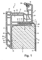
- the window frame body 1 shown in Fig. 1 consists of a hollow, extruded PVC profile with two mutually parallel and perpendicular and a Schaumstoffpaneel Sciences 2 surrounding hollow profile legs 3, 4, which are connected by a horizontal hollow profile part 5 to an approximately Z-profile.
- the horizontal hollow profile part 5 has a horizontal receiving groove 6 for the one of two legs 7, 8 of an existing metal frame 9.
- the two legs 7, 8 of the frame are approximately at right angles to each other.
- the thigh. 7 is received by the receiving groove 6, the surface 10 is provided with a corrugation or toothing 11 which is engageable with a surface toothing 12 of said one leg 7 in clamping engagement, as soon as the leg 7 is pressed into the receiving groove.
- FIG. 2 The toothing 11 of the surface 10 of the receiving groove 6 and the surface toothing 12 of the first leg 7 of the frame 9 are shown in FIG. 2 of obliquely placed teeth, which engage in the apparent from Fig. 1 insertion state of the frame 9 into each other and lock it with the profile body 1 ,
- both the receiving groove 6 and the frame 9 have a helical toothing.
- the toothing of the surface of the receiving groove or the surface toothing of the first leg of obliquely set teeth so that in the latter case, a combination of slanted teeth and straight teeth is possible.
- the obliquely placed teeth may be located in the region of the receiving groove or preferably on the frame, namely on the leg 7 of the frame 9.
- the leg 7 of the window frame 9 which can be inserted into the receiving groove 6 is provided on both sides with the surface toothing 12. Likewise, the receiving groove 6 on both sides of the toothing 11 in the region of its surface 10.
- the surface 10 of the receiving groove is only partially, preferably on one side, and the surface toothing 12 of the leg 7 at least partially, preferably one-sided, provided with the toothing or corrugation. It is clear that provided with the teeth surfaces of receiving groove and legs in the insertion state of the leg into the receiving groove facing each other, so that the teeth can act on each other and the leg and thus the entire frame is fixed in the inserted state.
- the teeth are inclined at approximately 45 ° and formed like a sawtooth with a steeply rising flank and an adjoining shallow sloping flank.
- 2 shows that the obliquely set teeth in the region of the receiving groove 6 each have a flank which rises steeply to the left and a flatter falling flank which adjoins the right.
- the leg 7 of the frame 1 teeth in which the steeply sloping edge are arranged on the right and the adjoining, gently sloping edge to the left.
- the leg 7 in the direction of arrow A can be inserted easily into the receiving groove 6; due to the tooth structure and the relative disposition of the teeth in the inserted state the leg 7 of the frame 9 can be relatively easily inserted or inserted into the receiving groove; However, the leg is reliably prevented from sliding out of the receiving groove due to the adjacent vertical tooth flanks. It is therefore not readily possible to pull the frame opposite to the insertion according to arrow A from the receiving groove 6.
- the height of the receiving groove 6 corresponds to the thickness of the leg 7 or differs slightly from the thickness of the leg 7, wherein the deviation in the range 0.1 to 0.7 mm, preferably 0.1 to 0.4 mm.
- the lower boundary wall 14 of the receiving groove 6 corresponds to the lower wall of the horizontal hollow profile part 5, and this wall rests on the Schaumstoffpaneel Sciences 2, which is also shown cut in the figures.
- the length of the receiving groove 6 is at least as large as the length of the inserted into it leg 7 of the window frame.
- the length of the leg 7 is in turn dimensioned so that the other leg 8 of the frame completely rests in the illustrated installation or insertion of the first leg on the surface 15 of the Schaumstoffpaneel stressess 2, wherein on the Schaumstoffpaleel endeavor a contact pressure is exerted, which the the panel body. 2 at least partially surrounding vertical hollow profile leg 3 presses against the surface of the panel body.
- Blendrahmenschenkels 7 is ensured on the surface of Schaumstoffpaneel Sciencess 2, in view of the special design of the surfaces of the frame frame legs and, if necessary, on the Schaumstoffpaneel Sciences 2 adjacent outer walls 25, 26 of the frame profile body, which will be explained below, is particularly durable and prevents destruction of the permanent connection between the frame and window frame profile body even with significant temperature fluctuations and other weather-related influences.
- a vertical hollow profile leg 3 and this with the other vertical hollow profile leg 2 connecting horizontal hollow profile part 5 each have one adjacent to the Schaumstoffpaneel Sciences 2 surface 31, 32 which is at least partially interlocked with the Schaumstoffpaneel Sciences 2 or by roughening or Corrugation is mechanically connected and helps ensure that an adhesive introduced between profile body 1 and 2 panel adhere better.
- the two vertical hollow profile legs 3, 4 and the horizontal hollow profile part 5 form a uniform whole and have cavities 16 to 21, which are closed to the outside and are at least partially stiffened by insert body, not shown, for example, made of metal.
- the cavities 16-21 of the hollow profile legs form chambers which are delimited by intermediate walls 22, 23 which separate and stiffen the outer walls 24, 25 of the hollow profile legs 3, 4 at a distance from one another and at least partially aligned at an angle with respect to the surfaces of these outer walls are in the illustrated embodiment ⁇ or> as 90 ° and corresponds to the angle at which the outer, the hollow profile legs 3, 4 and last chamber 16 final outer wall 30 extends.
- the intermediate walls 22, 23 extend parallel to the closing outer wall 30th
- the oblique outer wall 30 is circumferentially closed in the welded state and contributes substantially to better cleaning of the entire window construction in conjunction with the PU panel. This also applies to the fitting receiving groove 28 in the interior of the profile body.
- the oblique partition walls 22, 23 in the profile body 1 enable to shorten the profile leg 3, without losing the self-cleaning property.
- Such shortening of the profile body may be required, for example, in tight installation dimensions, if steel beams or concrete pillars are located too close to the window or on the door.
- a bending and torsion-resistant body is created, in particular in conjunction with the inserted into the receiving groove 6 frame, which is advantageously different from known window frame bodies of the type mentioned that he can be produced without major manufacturing and cost, yet Especially since the frame 9 only needs to be pressed into the receiving groove to produce a tight fit due to the corrugation or other mechanical surface structures of the contacting surfaces, its further particular advantage is that the frame the window frame of the profile body to the SchaumstoffpaneelSystem so that usually additional screwing of the sash body with the foam panel body can be avoided.
- the closure 27 of the upper groove 28 of the window frame body 1 and in particular its vertical leg 3 forms the possibility of securing the frame body against dirt particles penetrating from the outside and thereby keeping the profile body clean.
- the seal 29 located in the upper region of the hollow profile limb 4 is in the customary manner in a groove provided in the frame profile body 1 arranged, so that the window sash or door leaf, not shown, can be pressed tightly against the frame profile body 1 and penetration of moisture, especially rainwater, is prevented.
- the plastic profile according to the invention has a particular resistance to deflection due to wind pressure and wind suction and can be stiffened if necessary with steel profiles of different thickness, which are installed in the profiled body cavities, in addition.
- the stiffening of the construction in conjunction with the foamed PU panels 2 can be improved so that even can be dispensed with additional stiffening body as the steel profiles mentioned above.
- the upper double-walled version 33 of the two legs 3, 4 of the profile body 1 connecting hollow profile part 5 has the advantage of additional screwing of the profile, without being penetrated by this screw in the water leading level. Such a screw is particularly useful for extremely wide windows.
- the above frame body can be formed in adaptation to the respective panel thickness so that due to the inclined surface 34 of the frame 9 in the outer area can be dispensed with a window plate.
Landscapes
- Engineering & Computer Science (AREA)
- Civil Engineering (AREA)
- Structural Engineering (AREA)
- Wing Frames And Configurations (AREA)
- Securing Of Glass Panes Or The Like (AREA)
- Door And Window Frames Mounted To Openings (AREA)
- Extrusion Moulding Of Plastics Or The Like (AREA)
Claims (11)
- Élément d'encadrement constitué d'un profilé creux en forme de Z en matière plastique extrudée, en particulier en PVC, pour des fenêtres et des portes, comprenant deux branches approximativement parallèles s'étendant verticalement et entourant au moins partiellement un corps de panneau en mousse (2), lesdites branches étant reliées par une partie de profilé creuse (5) approximativement horizontale qui comporte une gorge de réception (6) dans laquelle peut être enfiché l'un des bras (7) d'un cadre de fermeture (9) constitué de deux bras (7, 8) convergeant l'un vers l'autre,
dans lequel la surface (10) de la gorge de réception (6) est pourvue d'une denture ou d'un moletage (11), susceptible d'être amené(e) en engagement de coincement avec une denture de surface (12) de l'un des bras (7), la hauteur de la gorge de réception (6) correspond à l'épaisseur du bras (7), la paroi de délimitation inférieure (14) de la gorge de réception (6) correspond à la paroi inférieure de la partie de profilé creuse (5) horizontale qui repose sur le corps de panneau en mousse (2), le second bras (8) exerce, dans l'état enfiché, sur la surface (15) du corps de panneau en mousse (2) une pression qui presse la branche de profilé creux (3) qui entoure au moins partiellement le corps de panneau en mousse (2) contre la surface du corps de panneau en mousse (2), les cavités (16-21) des branches de profilés creux (3-5) formant des cavités qui sont limitées par des parois intermédiaires (22, 23) qui séparent les parois extérieures allongées (24, 25) des branches de profilés creux (3, 4) à distance l'une de l'autre et qui renforcent ses parois, et
dans lequel les branches de profilés creux (3, 4) comportent à leurs extrémités libres une paroi extérieure (30) plus courte qui termine la branche de profilé creux ou respectivement la dernière chambre (16), ladite paroi extérieure étant orientée par rapport aux surfaces des parois extérieures allongées sous un angle qui est supérieur ou inférieur à 90°,
caractérisé en ce que
les parois intermédiaires (22, 23) de la branche de profilé creux (3) verticale qui entourent au moins partiellement le corps de panneau en mousse (2) sont orientées, au moins partiellement par rapport aux surfaces de ces parois extérieures (24, 25), sous un angle qui correspond à l'angle sous lequel s'étend la paroi extérieure (30) qui termine la branche de profilé creux (3, 4) ou respectivement la dernière chambre (16). - Élément d'encadrement selon la revendication 1, caractérisé en ce que la denture (11) de la surface (10) de la gorge de réception (6) et la denture de surface (12) du premier bras (7) sont constituées par des dents dressées en oblique, qui s'engagent les unes dans les autres à l'état enfiché du cadre de fermeture (9) et qui arrêtent le cadre de fermeture avec le corps profilé (1).
- Élément d'encadrement selon la revendication 1, caractérisé en ce que la denture (11) de la surface (10) de la gorge de réception (6) ou la denture de surface (12) du premier bras (7) est constituée par des dents dressées en oblique.
- Élément d'encadrement selon l'une des revendications précédentes, caractérisé en ce que la surface (10) de la gorge de réception (6) est dotée, au moins partiellement et de préférence d'un côté, de la denture ou du moletage (11), et la denture de surface (12) de l'un des bras (7) est dotée, au moins partiellement et de préférence d'un côté, de la denture ou du moletage (11).
- Élément d'encadrement selon l'une des revendications précédentes, caractérisé en ce que les deux branches de profilé creux verticales (3) et la partie de profilé creux horizontale (5) forment un tout unitaire et contiennent des cavités (16-21) qui sont refermées vers l'extérieur et qui sont rigidifiées au moins partiellement par des corps d'insert.
- Élément d'encadrement selon l'une des revendications précédentes, caractérisé en ce que l'une des branches de profilé creux verticale (3) et la partie de profilé creux horizontale (5) qui la relie à l'autre branche de profilé creux verticale (2) présentent chacune une paroi extérieure (25, 26) adjacente au corps de panneau en mousse (2), paroi extérieure dont la surface est au moins partiellement dentée ou rendue rugueuse pour renforcer la liaison avec le corps de panneau en mousse (2).
- Élément d'encadrement selon l'une des revendications précédentes, caractérisé en ce que la longueur de la gorge de réception (6) est au moins aussi élevée que la longueur du bras (7) du cadre de fermeture (9) enfiché dans cette gorge.
- Élément d'encadrement selon l'une des revendications précédentes, caractérisé en ce que la longueur du bras (7) est choisie de telle manière que l'autre bras (8) des deux bras (7, 8) du cadre de fermeture s'applique complètement sur la surface (15) du corps de panneau en mousse (2) à l'état d'enfichage du premier bras (7).
- Élément d'encadrement selon l'une des revendications précédentes, caractérisé en ce que l'autre bras (8) est pourvu d'une denture de surface ou d'un moletage (13) sur au moins une partie de sa surface qui entre en contact avec le corps de panneau en mousse (2).
- Élément d'encadrement selon l'une des revendications précédentes, caractérisé en ce que les deux bras (7, 8) du cadre de fermeture sont reliés l'un à l'autre par une surface oblique (34) qui remplit aussi la fonction d'une tablette de fenêtre.
- Élément d'encadrement selon l'une des revendications précédentes, caractérisé en ce que la hauteur de la gorge de réception (6) s'écarte légèrement de l'épaisseur du bras (7) du cadre de fermeture (9) susceptible d'être enfiché dans la gorge de réception (6), et l'écart est situé dans la plage de 0,1 à 0,7 mm, de préférence de 0,1 à 0,4 mm.
Applications Claiming Priority (2)
| Application Number | Priority Date | Filing Date | Title |
|---|---|---|---|
| DE202004000817U | 2004-01-20 | ||
| DE202004000817U DE202004000817U1 (de) | 2004-01-20 | 2004-01-20 | Rahmenkörper aus einem hohlen, stranggepreßten Kunststoffprofil für Fenster und Türen |
Publications (3)
| Publication Number | Publication Date |
|---|---|
| EP1557519A2 EP1557519A2 (fr) | 2005-07-27 |
| EP1557519A3 EP1557519A3 (fr) | 2006-01-18 |
| EP1557519B1 true EP1557519B1 (fr) | 2006-11-22 |
Family
ID=32319272
Family Applications (1)
| Application Number | Title | Priority Date | Filing Date |
|---|---|---|---|
| EP05000952A Expired - Lifetime EP1557519B1 (fr) | 2004-01-20 | 2005-01-18 | Elément d'encadrement pour portes ou fenêtres constitué par un profilé creux en matière plastique extrudé |
Country Status (4)
| Country | Link |
|---|---|
| EP (1) | EP1557519B1 (fr) |
| AT (1) | ATE346215T1 (fr) |
| DE (2) | DE202004000817U1 (fr) |
| ES (1) | ES2278356T3 (fr) |
Cited By (2)
| Publication number | Priority date | Publication date | Assignee | Title |
|---|---|---|---|---|
| EP2184433A1 (fr) | 2008-11-11 | 2010-05-12 | Werner Fech | Corps de cadre pour fenêtres ou portes |
| RU180242U1 (ru) * | 2018-03-05 | 2018-06-06 | Юрий Владимирович Эпштейн | Профиль дверной коробки |
Families Citing this family (6)
| Publication number | Priority date | Publication date | Assignee | Title |
|---|---|---|---|---|
| GB2434611A (en) * | 2006-01-30 | 2007-08-01 | Barry Bates | Adjustable window frame |
| DE202013105309U1 (de) * | 2013-11-22 | 2015-02-27 | Carsten Böttcher | Türzarge |
| CN104405234B (zh) * | 2014-12-09 | 2016-05-25 | 孙宝山 | 一种用于活动板房的快速安装一体窗 |
| DE202019106986U1 (de) | 2019-12-16 | 2020-03-12 | Andreas Gerstmeier | Windenhalterung, Rampe und Fahrzeugheckträger |
| BR102021020102A2 (pt) * | 2021-04-26 | 2022-05-31 | Jose Sabadin Uldemar | Conjunto marco monobloco universal com arremates dotados de vista interna e externa e espuma de vedação |
| US11391083B1 (en) * | 2021-12-03 | 2022-07-19 | Steelworks Etc. Inc. | Composite fenestration assembly |
Family Cites Families (4)
| Publication number | Priority date | Publication date | Assignee | Title |
|---|---|---|---|---|
| GB1216370A (en) * | 1967-07-07 | 1970-12-23 | Monsanto Co | Frames |
| DE29614882U1 (de) * | 1996-08-27 | 1996-12-19 | Fa. Franz Karl, 86707 Westendorf | Anordnung zur Schutzabdeckung eines auf der Außenseite des Blendrahmens eines Kunststoff-Fensters oder einer Kunststoff-Türe vorspringenden Stufenabsatzes mittels einer Abdeckung |
| GB2341410A (en) * | 1998-09-09 | 2000-03-15 | Selecta Window Systems Limited | Window mounting method |
| DE10108424B4 (de) * | 2001-02-21 | 2004-03-11 | Werner Fech | Blendrahmen zur Abdeckung von Fensteröffnungen in geschäumten Sandwichpaneelen und Verfahren zum Einbau |
-
2004
- 2004-01-20 DE DE202004000817U patent/DE202004000817U1/de not_active Expired - Lifetime
-
2005
- 2005-01-18 AT AT05000952T patent/ATE346215T1/de active
- 2005-01-18 EP EP05000952A patent/EP1557519B1/fr not_active Expired - Lifetime
- 2005-01-18 ES ES05000952T patent/ES2278356T3/es not_active Expired - Lifetime
- 2005-01-18 DE DE502005000190T patent/DE502005000190D1/de not_active Expired - Lifetime
Cited By (2)
| Publication number | Priority date | Publication date | Assignee | Title |
|---|---|---|---|---|
| EP2184433A1 (fr) | 2008-11-11 | 2010-05-12 | Werner Fech | Corps de cadre pour fenêtres ou portes |
| RU180242U1 (ru) * | 2018-03-05 | 2018-06-06 | Юрий Владимирович Эпштейн | Профиль дверной коробки |
Also Published As
| Publication number | Publication date |
|---|---|
| ES2278356T3 (es) | 2007-08-01 |
| EP1557519A3 (fr) | 2006-01-18 |
| ATE346215T1 (de) | 2006-12-15 |
| DE202004000817U1 (de) | 2004-05-13 |
| DE502005000190D1 (de) | 2007-01-04 |
| EP1557519A2 (fr) | 2005-07-27 |
Similar Documents
| Publication | Publication Date | Title |
|---|---|---|
| EP0616107B1 (fr) | Raccord à onglet d'éléments profilés | |
| EP1555376A1 (fr) | Profilé composite | |
| EP0610674A1 (fr) | Joint d'angle à onglet de profilés creux pour cadres de fenêtres, portes ou façades | |
| DE2313425A1 (de) | Flanschverbindung zum gegenseitigen befestigen von im querschnitt im wesentlichen rechteckigen kanalteilstuecken aus blech, insbesondere fuer lufttechnische hochdruckanlagen | |
| EP1557519B1 (fr) | Elément d'encadrement pour portes ou fenêtres constitué par un profilé creux en matière plastique extrudé | |
| EP2666948A1 (fr) | Agencement de cadre pour un panneau de porte sectionnelle | |
| EP0814228A2 (fr) | Profilé de renforcement pour profilés creux en matière plastique pour la production des fenêtres, portes etc. | |
| DE3532593A1 (de) | Extrudierter kunststoffhohlprofilstab fuer rahmen von fenstern und tueren | |
| EP1659254B1 (fr) | Vantail de porte ou fenêtre | |
| EP0477544B1 (fr) | Pièce de remplissage pour parcloses | |
| WO2019149301A1 (fr) | Système de positionnement d'une pièce plate au niveau d'un châssis d'armoire électrique et procédé correspondant | |
| DE19904695A1 (de) | Kämpferverbinder | |
| AT402530B (de) | Türflügel für gebäudeaussentür | |
| DE4042398C2 (fr) | ||
| EP0857847A2 (fr) | Procédé d'assemblage de vitrages isolants avec espaceur thermoplastique et petits bois insérés, petits bois y afférent et vitrages isolants en pourvus | |
| DE202010016979U1 (de) | Lichtband und Hallenwand mit einem Lichtband | |
| CH663058A5 (de) | Aluminium-fensterbank. | |
| EP2060726A2 (fr) | Profilé creux | |
| EP0450265B1 (fr) | Revêtement de bord pour rebords de fenêtre minces | |
| DE3301324A1 (de) | Verbesserungen bei rahmenteilen fuer fenster, tueren und anderen rahmenkonstruktionen | |
| AT408371B (de) | Zargenfenster | |
| DE202023002954U1 (de) | Rahmenausbildung als Teil eines Paneelelementes für ein Sektionaltorblatt | |
| AT397542B (de) | Rahmen für rolladen | |
| DE202025105287U1 (de) | Verbindung zwischen einem Pfosten und einem Riegel, Konstruktion umfassend mindestens einen Riegel und mindestens einen Pfosten verbunden durch eine Verbindung | |
| EP4112864A1 (fr) | Dispositif de liaison de sections d'onglet |
Legal Events
| Date | Code | Title | Description |
|---|---|---|---|
| PUAI | Public reference made under article 153(3) epc to a published international application that has entered the european phase |
Free format text: ORIGINAL CODE: 0009012 |
|
| AK | Designated contracting states |
Kind code of ref document: A2 Designated state(s): AT BE BG CH CY CZ DE DK EE ES FI FR GB GR HU IE IS IT LI LT LU MC NL PL PT RO SE SI SK TR |
|
| AX | Request for extension of the european patent |
Extension state: AL BA HR LV MK YU |
|
| 17P | Request for examination filed |
Effective date: 20050818 |
|
| PUAL | Search report despatched |
Free format text: ORIGINAL CODE: 0009013 |
|
| AK | Designated contracting states |
Kind code of ref document: A3 Designated state(s): AT BE BG CH CY CZ DE DK EE ES FI FR GB GR HU IE IS IT LI LT LU MC NL PL PT RO SE SI SK TR |
|
| AX | Request for extension of the european patent |
Extension state: AL BA HR LV MK YU |
|
| GRAP | Despatch of communication of intention to grant a patent |
Free format text: ORIGINAL CODE: EPIDOSNIGR1 |
|
| AKX | Designation fees paid |
Designated state(s): AT BE BG CH CY CZ DE DK EE ES FI FR GB GR HU IE IS IT LI LT LU MC NL PL PT RO SE SI SK TR |
|
| GRAS | Grant fee paid |
Free format text: ORIGINAL CODE: EPIDOSNIGR3 |
|
| GRAA | (expected) grant |
Free format text: ORIGINAL CODE: 0009210 |
|
| AK | Designated contracting states |
Kind code of ref document: B1 Designated state(s): AT BE BG CH CY CZ DE DK EE ES FI FR GB GR HU IE IS IT LI LT LU MC NL PL PT RO SE SI SK TR |
|
| PG25 | Lapsed in a contracting state [announced via postgrant information from national office to epo] |
Ref country code: LT Free format text: LAPSE BECAUSE OF FAILURE TO SUBMIT A TRANSLATION OF THE DESCRIPTION OR TO PAY THE FEE WITHIN THE PRESCRIBED TIME-LIMIT Effective date: 20061122 Ref country code: SK Free format text: LAPSE BECAUSE OF FAILURE TO SUBMIT A TRANSLATION OF THE DESCRIPTION OR TO PAY THE FEE WITHIN THE PRESCRIBED TIME-LIMIT Effective date: 20061122 Ref country code: FI Free format text: LAPSE BECAUSE OF FAILURE TO SUBMIT A TRANSLATION OF THE DESCRIPTION OR TO PAY THE FEE WITHIN THE PRESCRIBED TIME-LIMIT Effective date: 20061122 Ref country code: IE Free format text: LAPSE BECAUSE OF FAILURE TO SUBMIT A TRANSLATION OF THE DESCRIPTION OR TO PAY THE FEE WITHIN THE PRESCRIBED TIME-LIMIT Effective date: 20061122 Ref country code: RO Free format text: LAPSE BECAUSE OF FAILURE TO SUBMIT A TRANSLATION OF THE DESCRIPTION OR TO PAY THE FEE WITHIN THE PRESCRIBED TIME-LIMIT Effective date: 20061122 Ref country code: SI Free format text: LAPSE BECAUSE OF FAILURE TO SUBMIT A TRANSLATION OF THE DESCRIPTION OR TO PAY THE FEE WITHIN THE PRESCRIBED TIME-LIMIT Effective date: 20061122 Ref country code: PL Free format text: LAPSE BECAUSE OF FAILURE TO SUBMIT A TRANSLATION OF THE DESCRIPTION OR TO PAY THE FEE WITHIN THE PRESCRIBED TIME-LIMIT Effective date: 20061122 |
|
| REG | Reference to a national code |
Ref country code: GB Ref legal event code: FG4D Free format text: NOT ENGLISH |
|
| REG | Reference to a national code |
Ref country code: CH Ref legal event code: EP |
|
| REG | Reference to a national code |
Ref country code: IE Ref legal event code: FG4D Free format text: LANGUAGE OF EP DOCUMENT: GERMAN |
|
| REF | Corresponds to: |
Ref document number: 502005000190 Country of ref document: DE Date of ref document: 20070104 Kind code of ref document: P |
|
| PG25 | Lapsed in a contracting state [announced via postgrant information from national office to epo] |
Ref country code: MC Free format text: LAPSE BECAUSE OF NON-PAYMENT OF DUE FEES Effective date: 20070131 |
|
| PG25 | Lapsed in a contracting state [announced via postgrant information from national office to epo] |
Ref country code: DK Free format text: LAPSE BECAUSE OF FAILURE TO SUBMIT A TRANSLATION OF THE DESCRIPTION OR TO PAY THE FEE WITHIN THE PRESCRIBED TIME-LIMIT Effective date: 20070222 Ref country code: BG Free format text: LAPSE BECAUSE OF FAILURE TO SUBMIT A TRANSLATION OF THE DESCRIPTION OR TO PAY THE FEE WITHIN THE PRESCRIBED TIME-LIMIT Effective date: 20070222 Ref country code: SE Free format text: LAPSE BECAUSE OF FAILURE TO SUBMIT A TRANSLATION OF THE DESCRIPTION OR TO PAY THE FEE WITHIN THE PRESCRIBED TIME-LIMIT Effective date: 20070222 |
|
| PG25 | Lapsed in a contracting state [announced via postgrant information from national office to epo] |
Ref country code: IS Free format text: LAPSE BECAUSE OF FAILURE TO SUBMIT A TRANSLATION OF THE DESCRIPTION OR TO PAY THE FEE WITHIN THE PRESCRIBED TIME-LIMIT Effective date: 20070322 |
|
| PG25 | Lapsed in a contracting state [announced via postgrant information from national office to epo] |
Ref country code: PT Free format text: LAPSE BECAUSE OF FAILURE TO SUBMIT A TRANSLATION OF THE DESCRIPTION OR TO PAY THE FEE WITHIN THE PRESCRIBED TIME-LIMIT Effective date: 20070423 |
|
| REG | Reference to a national code |
Ref country code: CH Ref legal event code: NV Representative=s name: HANS RUDOLF GACHNANG PATENTANWALT |
|
| GBV | Gb: ep patent (uk) treated as always having been void in accordance with gb section 77(7)/1977 [no translation filed] |
Effective date: 20061122 |
|
| REG | Reference to a national code |
Ref country code: IE Ref legal event code: FD4D |
|
| REG | Reference to a national code |
Ref country code: HU Ref legal event code: AG4A Ref document number: E001511 Country of ref document: HU |
|
| EN | Fr: translation not filed | ||
| REG | Reference to a national code |
Ref country code: ES Ref legal event code: FG2A Ref document number: 2278356 Country of ref document: ES Kind code of ref document: T3 |
|
| PLBE | No opposition filed within time limit |
Free format text: ORIGINAL CODE: 0009261 |
|
| STAA | Information on the status of an ep patent application or granted ep patent |
Free format text: STATUS: NO OPPOSITION FILED WITHIN TIME LIMIT |
|
| 26N | No opposition filed |
Effective date: 20070823 |
|
| PG25 | Lapsed in a contracting state [announced via postgrant information from national office to epo] |
Ref country code: GB Free format text: LAPSE BECAUSE OF FAILURE TO SUBMIT A TRANSLATION OF THE DESCRIPTION OR TO PAY THE FEE WITHIN THE PRESCRIBED TIME-LIMIT Effective date: 20061122 |
|
| BERE | Be: lapsed |
Owner name: FECH, WERNER Effective date: 20070131 |
|
| PG25 | Lapsed in a contracting state [announced via postgrant information from national office to epo] |
Ref country code: BE Free format text: LAPSE BECAUSE OF NON-PAYMENT OF DUE FEES Effective date: 20070131 |
|
| PG25 | Lapsed in a contracting state [announced via postgrant information from national office to epo] |
Ref country code: GR Free format text: LAPSE BECAUSE OF FAILURE TO SUBMIT A TRANSLATION OF THE DESCRIPTION OR TO PAY THE FEE WITHIN THE PRESCRIBED TIME-LIMIT Effective date: 20070223 Ref country code: FR Free format text: LAPSE BECAUSE OF FAILURE TO SUBMIT A TRANSLATION OF THE DESCRIPTION OR TO PAY THE FEE WITHIN THE PRESCRIBED TIME-LIMIT Effective date: 20070713 |
|
| PG25 | Lapsed in a contracting state [announced via postgrant information from national office to epo] |
Ref country code: FR Free format text: LAPSE BECAUSE OF FAILURE TO SUBMIT A TRANSLATION OF THE DESCRIPTION OR TO PAY THE FEE WITHIN THE PRESCRIBED TIME-LIMIT Effective date: 20061122 |
|
| PG25 | Lapsed in a contracting state [announced via postgrant information from national office to epo] |
Ref country code: EE Free format text: LAPSE BECAUSE OF FAILURE TO SUBMIT A TRANSLATION OF THE DESCRIPTION OR TO PAY THE FEE WITHIN THE PRESCRIBED TIME-LIMIT Effective date: 20061122 |
|
| PG25 | Lapsed in a contracting state [announced via postgrant information from national office to epo] |
Ref country code: LU Free format text: LAPSE BECAUSE OF NON-PAYMENT OF DUE FEES Effective date: 20070118 Ref country code: CY Free format text: LAPSE BECAUSE OF FAILURE TO SUBMIT A TRANSLATION OF THE DESCRIPTION OR TO PAY THE FEE WITHIN THE PRESCRIBED TIME-LIMIT Effective date: 20061122 |
|
| PG25 | Lapsed in a contracting state [announced via postgrant information from national office to epo] |
Ref country code: TR Free format text: LAPSE BECAUSE OF FAILURE TO SUBMIT A TRANSLATION OF THE DESCRIPTION OR TO PAY THE FEE WITHIN THE PRESCRIBED TIME-LIMIT Effective date: 20061122 |
|
| PGFP | Annual fee paid to national office [announced via postgrant information from national office to epo] |
Ref country code: IT Payment date: 20120123 Year of fee payment: 8 |
|
| PGFP | Annual fee paid to national office [announced via postgrant information from national office to epo] |
Ref country code: CZ Payment date: 20130109 Year of fee payment: 9 Ref country code: HU Payment date: 20130117 Year of fee payment: 9 Ref country code: CH Payment date: 20130125 Year of fee payment: 9 Ref country code: ES Payment date: 20130128 Year of fee payment: 9 |
|
| PGFP | Annual fee paid to national office [announced via postgrant information from national office to epo] |
Ref country code: NL Payment date: 20130125 Year of fee payment: 9 |
|
| PGFP | Annual fee paid to national office [announced via postgrant information from national office to epo] |
Ref country code: AT Payment date: 20130103 Year of fee payment: 9 |
|
| PGFP | Annual fee paid to national office [announced via postgrant information from national office to epo] |
Ref country code: DE Payment date: 20130402 Year of fee payment: 9 |
|
| REG | Reference to a national code |
Ref country code: CH Ref legal event code: NV Representative=s name: GACHNANG AG PATENTANWAELTE, CH |
|
| REG | Reference to a national code |
Ref country code: DE Ref legal event code: R119 Ref document number: 502005000190 Country of ref document: DE |
|
| REG | Reference to a national code |
Ref country code: NL Ref legal event code: V1 Effective date: 20140801 |
|
| REG | Reference to a national code |
Ref country code: CH Ref legal event code: PL |
|
| REG | Reference to a national code |
Ref country code: AT Ref legal event code: MM01 Ref document number: 346215 Country of ref document: AT Kind code of ref document: T Effective date: 20140118 |
|
| REG | Reference to a national code |
Ref country code: DE Ref legal event code: R119 Ref document number: 502005000190 Country of ref document: DE Effective date: 20140801 |
|
| PG25 | Lapsed in a contracting state [announced via postgrant information from national office to epo] |
Ref country code: CH Free format text: LAPSE BECAUSE OF NON-PAYMENT OF DUE FEES Effective date: 20140131 Ref country code: DE Free format text: LAPSE BECAUSE OF NON-PAYMENT OF DUE FEES Effective date: 20140801 Ref country code: LI Free format text: LAPSE BECAUSE OF NON-PAYMENT OF DUE FEES Effective date: 20140131 Ref country code: CZ Free format text: LAPSE BECAUSE OF NON-PAYMENT OF DUE FEES Effective date: 20140118 Ref country code: NL Free format text: LAPSE BECAUSE OF NON-PAYMENT OF DUE FEES Effective date: 20140801 |
|
| PG25 | Lapsed in a contracting state [announced via postgrant information from national office to epo] |
Ref country code: AT Free format text: LAPSE BECAUSE OF NON-PAYMENT OF DUE FEES Effective date: 20140118 Ref country code: HU Free format text: LAPSE BECAUSE OF NON-PAYMENT OF DUE FEES Effective date: 20140119 |
|
| REG | Reference to a national code |
Ref country code: ES Ref legal event code: FD2A Effective date: 20150507 |
|
| PG25 | Lapsed in a contracting state [announced via postgrant information from national office to epo] |
Ref country code: ES Free format text: LAPSE BECAUSE OF NON-PAYMENT OF DUE FEES Effective date: 20140119 |
|
| PG25 | Lapsed in a contracting state [announced via postgrant information from national office to epo] |
Ref country code: IT Free format text: LAPSE BECAUSE OF NON-PAYMENT OF DUE FEES Effective date: 20140118 |