EP1557597A1 - Soupape de régulation de pression d'une rampe commune d'un moteur à combustion interne - Google Patents
Soupape de régulation de pression d'une rampe commune d'un moteur à combustion interne Download PDFInfo
- Publication number
- EP1557597A1 EP1557597A1 EP04028091A EP04028091A EP1557597A1 EP 1557597 A1 EP1557597 A1 EP 1557597A1 EP 04028091 A EP04028091 A EP 04028091A EP 04028091 A EP04028091 A EP 04028091A EP 1557597 A1 EP1557597 A1 EP 1557597A1
- Authority
- EP
- European Patent Office
- Prior art keywords
- control valve
- pressure control
- pressure
- spring
- valve
- Prior art date
- Legal status (The legal status is an assumption and is not a legal conclusion. Google has not performed a legal analysis and makes no representation as to the accuracy of the status listed.)
- Granted
Links
- 238000002485 combustion reaction Methods 0.000 title claims abstract description 14
- 238000007789 sealing Methods 0.000 claims description 11
- 230000001105 regulatory effect Effects 0.000 abstract description 10
- 239000000446 fuel Substances 0.000 description 17
- 230000006835 compression Effects 0.000 description 8
- 238000007906 compression Methods 0.000 description 8
- 125000006850 spacer group Chemical group 0.000 description 4
- 230000001276 controlling effect Effects 0.000 description 3
- 239000000853 adhesive Substances 0.000 description 2
- 230000001070 adhesive effect Effects 0.000 description 2
- 238000005553 drilling Methods 0.000 description 2
- 239000002828 fuel tank Substances 0.000 description 2
- 238000002347 injection Methods 0.000 description 2
- 239000007924 injection Substances 0.000 description 2
- 238000002788 crimping Methods 0.000 description 1
- 230000007423 decrease Effects 0.000 description 1
- 230000001934 delay Effects 0.000 description 1
- 230000001747 exhibiting effect Effects 0.000 description 1
- 239000012535 impurity Substances 0.000 description 1
- 238000001746 injection moulding Methods 0.000 description 1
- 239000007788 liquid Substances 0.000 description 1
- 238000000034 method Methods 0.000 description 1
- 230000003068 static effect Effects 0.000 description 1
- 230000003319 supportive effect Effects 0.000 description 1
Images

Classifications
-
- F—MECHANICAL ENGINEERING; LIGHTING; HEATING; WEAPONS; BLASTING
- F16—ENGINEERING ELEMENTS AND UNITS; GENERAL MEASURES FOR PRODUCING AND MAINTAINING EFFECTIVE FUNCTIONING OF MACHINES OR INSTALLATIONS; THERMAL INSULATION IN GENERAL
- F16K—VALVES; TAPS; COCKS; ACTUATING-FLOATS; DEVICES FOR VENTING OR AERATING
- F16K31/00—Actuating devices; Operating means; Releasing devices
- F16K31/02—Actuating devices; Operating means; Releasing devices electric; magnetic
- F16K31/06—Actuating devices; Operating means; Releasing devices electric; magnetic using a magnet, e.g. diaphragm valves, cutting off by means of a liquid
- F16K31/0644—One-way valve
- F16K31/0655—Lift valves
-
- F—MECHANICAL ENGINEERING; LIGHTING; HEATING; WEAPONS; BLASTING
- F02—COMBUSTION ENGINES; HOT-GAS OR COMBUSTION-PRODUCT ENGINE PLANTS
- F02M—SUPPLYING COMBUSTION ENGINES IN GENERAL WITH COMBUSTIBLE MIXTURES OR CONSTITUENTS THEREOF
- F02M63/00—Other fuel-injection apparatus having pertinent characteristics not provided for in groups F02M39/00 - F02M57/00 or F02M67/00; Details, component parts, or accessories of fuel-injection apparatus, not provided for in, or of interest apart from, the apparatus of groups F02M39/00 - F02M61/00 or F02M67/00; Combination of fuel pump with other devices, e.g. lubricating oil pump
- F02M63/0012—Valves
- F02M63/0031—Valves characterized by the type of valves, e.g. special valve member details, valve seat details, valve housing details
- F02M63/005—Pressure relief valves
- F02M63/0052—Pressure relief valves with means for adjusting the opening pressure, e.g. electrically controlled
-
- F—MECHANICAL ENGINEERING; LIGHTING; HEATING; WEAPONS; BLASTING
- F02—COMBUSTION ENGINES; HOT-GAS OR COMBUSTION-PRODUCT ENGINE PLANTS
- F02M—SUPPLYING COMBUSTION ENGINES IN GENERAL WITH COMBUSTIBLE MIXTURES OR CONSTITUENTS THEREOF
- F02M63/00—Other fuel-injection apparatus having pertinent characteristics not provided for in groups F02M39/00 - F02M57/00 or F02M67/00; Details, component parts, or accessories of fuel-injection apparatus, not provided for in, or of interest apart from, the apparatus of groups F02M39/00 - F02M61/00 or F02M67/00; Combination of fuel pump with other devices, e.g. lubricating oil pump
- F02M63/02—Fuel-injection apparatus having several injectors fed by a common pumping element, or having several pumping elements feeding a common injector; Fuel-injection apparatus having provisions for cutting-out pumps, pumping elements, or injectors; Fuel-injection apparatus having provisions for variably interconnecting pumping elements and injectors alternatively
- F02M63/0225—Fuel-injection apparatus having a common rail feeding several injectors ; Means for varying pressure in common rails; Pumps feeding common rails
-
- F—MECHANICAL ENGINEERING; LIGHTING; HEATING; WEAPONS; BLASTING
- F02—COMBUSTION ENGINES; HOT-GAS OR COMBUSTION-PRODUCT ENGINE PLANTS
- F02M—SUPPLYING COMBUSTION ENGINES IN GENERAL WITH COMBUSTIBLE MIXTURES OR CONSTITUENTS THEREOF
- F02M63/00—Other fuel-injection apparatus having pertinent characteristics not provided for in groups F02M39/00 - F02M57/00 or F02M67/00; Details, component parts, or accessories of fuel-injection apparatus, not provided for in, or of interest apart from, the apparatus of groups F02M39/00 - F02M61/00 or F02M67/00; Combination of fuel pump with other devices, e.g. lubricating oil pump
- F02M63/02—Fuel-injection apparatus having several injectors fed by a common pumping element, or having several pumping elements feeding a common injector; Fuel-injection apparatus having provisions for cutting-out pumps, pumping elements, or injectors; Fuel-injection apparatus having provisions for variably interconnecting pumping elements and injectors alternatively
- F02M63/0225—Fuel-injection apparatus having a common rail feeding several injectors ; Means for varying pressure in common rails; Pumps feeding common rails
- F02M63/023—Means for varying pressure in common rails
- F02M63/0235—Means for varying pressure in common rails by bleeding fuel pressure
- F02M63/025—Means for varying pressure in common rails by bleeding fuel pressure from the common rail
-
- F—MECHANICAL ENGINEERING; LIGHTING; HEATING; WEAPONS; BLASTING
- F02—COMBUSTION ENGINES; HOT-GAS OR COMBUSTION-PRODUCT ENGINE PLANTS
- F02M—SUPPLYING COMBUSTION ENGINES IN GENERAL WITH COMBUSTIBLE MIXTURES OR CONSTITUENTS THEREOF
- F02M63/00—Other fuel-injection apparatus having pertinent characteristics not provided for in groups F02M39/00 - F02M57/00 or F02M67/00; Details, component parts, or accessories of fuel-injection apparatus, not provided for in, or of interest apart from, the apparatus of groups F02M39/00 - F02M61/00 or F02M67/00; Combination of fuel pump with other devices, e.g. lubricating oil pump
- F02M63/02—Fuel-injection apparatus having several injectors fed by a common pumping element, or having several pumping elements feeding a common injector; Fuel-injection apparatus having provisions for cutting-out pumps, pumping elements, or injectors; Fuel-injection apparatus having provisions for variably interconnecting pumping elements and injectors alternatively
- F02M63/0225—Fuel-injection apparatus having a common rail feeding several injectors ; Means for varying pressure in common rails; Pumps feeding common rails
- F02M63/023—Means for varying pressure in common rails
- F02M63/026—Means for reducing the pressure in common rails at power off
-
- F—MECHANICAL ENGINEERING; LIGHTING; HEATING; WEAPONS; BLASTING
- F16—ENGINEERING ELEMENTS AND UNITS; GENERAL MEASURES FOR PRODUCING AND MAINTAINING EFFECTIVE FUNCTIONING OF MACHINES OR INSTALLATIONS; THERMAL INSULATION IN GENERAL
- F16K—VALVES; TAPS; COCKS; ACTUATING-FLOATS; DEVICES FOR VENTING OR AERATING
- F16K31/00—Actuating devices; Operating means; Releasing devices
- F16K31/02—Actuating devices; Operating means; Releasing devices electric; magnetic
- F16K31/06—Actuating devices; Operating means; Releasing devices electric; magnetic using a magnet, e.g. diaphragm valves, cutting off by means of a liquid
- F16K31/0644—One-way valve
- F16K31/0655—Lift valves
- F16K31/0665—Lift valves with valve member being at least partially ball-shaped
-
- G—PHYSICS
- G05—CONTROLLING; REGULATING
- G05D—SYSTEMS FOR CONTROLLING OR REGULATING NON-ELECTRIC VARIABLES
- G05D16/00—Control of fluid pressure
- G05D16/20—Control of fluid pressure characterised by the use of electric means
- G05D16/2006—Control of fluid pressure characterised by the use of electric means with direct action of electric energy on controlling means
- G05D16/2013—Control of fluid pressure characterised by the use of electric means with direct action of electric energy on controlling means using throttling means as controlling means
- G05D16/2022—Control of fluid pressure characterised by the use of electric means with direct action of electric energy on controlling means using throttling means as controlling means actuated by a proportional solenoid
-
- F—MECHANICAL ENGINEERING; LIGHTING; HEATING; WEAPONS; BLASTING
- F02—COMBUSTION ENGINES; HOT-GAS OR COMBUSTION-PRODUCT ENGINE PLANTS
- F02M—SUPPLYING COMBUSTION ENGINES IN GENERAL WITH COMBUSTIBLE MIXTURES OR CONSTITUENTS THEREOF
- F02M2200/00—Details of fuel-injection apparatus, not otherwise provided for
- F02M2200/50—Arrangements of springs for valves used in fuel injectors or fuel injection pumps
-
- F—MECHANICAL ENGINEERING; LIGHTING; HEATING; WEAPONS; BLASTING
- F02—COMBUSTION ENGINES; HOT-GAS OR COMBUSTION-PRODUCT ENGINE PLANTS
- F02M—SUPPLYING COMBUSTION ENGINES IN GENERAL WITH COMBUSTIBLE MIXTURES OR CONSTITUENTS THEREOF
- F02M2200/00—Details of fuel-injection apparatus, not otherwise provided for
- F02M2200/50—Arrangements of springs for valves used in fuel injectors or fuel injection pumps
- F02M2200/502—Springs biasing the valve member to the open position
-
- F—MECHANICAL ENGINEERING; LIGHTING; HEATING; WEAPONS; BLASTING
- F02—COMBUSTION ENGINES; HOT-GAS OR COMBUSTION-PRODUCT ENGINE PLANTS
- F02M—SUPPLYING COMBUSTION ENGINES IN GENERAL WITH COMBUSTIBLE MIXTURES OR CONSTITUENTS THEREOF
- F02M2200/00—Details of fuel-injection apparatus, not otherwise provided for
- F02M2200/60—Fuel-injection apparatus having means for facilitating the starting of engines, e.g. with valves or fuel passages for keeping residual pressure in common rails
-
- F—MECHANICAL ENGINEERING; LIGHTING; HEATING; WEAPONS; BLASTING
- F02—COMBUSTION ENGINES; HOT-GAS OR COMBUSTION-PRODUCT ENGINE PLANTS
- F02M—SUPPLYING COMBUSTION ENGINES IN GENERAL WITH COMBUSTIBLE MIXTURES OR CONSTITUENTS THEREOF
- F02M63/00—Other fuel-injection apparatus having pertinent characteristics not provided for in groups F02M39/00 - F02M57/00 or F02M67/00; Details, component parts, or accessories of fuel-injection apparatus, not provided for in, or of interest apart from, the apparatus of groups F02M39/00 - F02M61/00 or F02M67/00; Combination of fuel pump with other devices, e.g. lubricating oil pump
- F02M63/0012—Valves
- F02M63/0031—Valves characterized by the type of valves, e.g. special valve member details, valve seat details, valve housing details
- F02M63/0033—Lift valves, i.e. having a valve member that moves perpendicularly to the plane of the valve seat
- F02M63/0036—Lift valves, i.e. having a valve member that moves perpendicularly to the plane of the valve seat with spherical or partly spherical shaped valve member ends
-
- H—ELECTRICITY
- H01—ELECTRIC ELEMENTS
- H01F—MAGNETS; INDUCTANCES; TRANSFORMERS; SELECTION OF MATERIALS FOR THEIR MAGNETIC PROPERTIES
- H01F7/00—Magnets
- H01F7/06—Electromagnets; Actuators including electromagnets
- H01F7/08—Electromagnets; Actuators including electromagnets with armatures
- H01F7/16—Rectilinearly-movable armatures
- H01F7/1607—Armatures entering the winding
Definitions
- a metering unit and / or a pressure regulating valve is used for controlling the fuel pressure in the high-pressure accumulator of self-igniting internal combustion engines.
- the pressure control valve is closed when it is not subjected to a voltage. For this reason, the fuel in the high-pressure accumulator after stopping the engine enclosed and separated from the fuel return.
- the closing force to Closing the high-pressure accumulator is generated by a spring element, which is mounted above the armature plate of the actuator for controlling the valve and the Closing element at the opposite end of the armature plate of the valve piston in puts his seat.
- a pressure control valve is from diesel engine management, 2. Edition, Vieweg-Verlag, 1998, pages 270-271.
- Fuel injectors powered by piezo actuators do not leak leaks on. Thus, no fuel from the return lines of the injectors in the high-pressure accumulator reach. Once the fuel pressure in the high-pressure accumulator under the Vapor pressure of the dissolved air in the fuel, the air is released, so that next to the liquid fuel and a gas phase in the high-pressure accumulator is included.
- the inventively designed pressure control valve for opening or closing a Expiration of a high-pressure accumulator of an internal combustion engine comprises an actuator operated Closing element, which is a connection from the high pressure accumulator in a low pressure line closes or releases.
- a spring element is arranged such that at standstill of the internal combustion engine, the closing element the connection from the high pressure accumulator releases into the low pressure line. This will be it allows fuel to come out of the return line when the internal combustion engine is at a standstill can get into the high-pressure accumulator. This avoids that the Pressure in the high-pressure accumulator below the vapor pressure of the air dissolved in the fuel sinks. This means that even when the cold start of the internal combustion engine immediately Pressure in the high-pressure accumulator can be built and thus eliminates the start delay becomes.
- the spring element is for Opening the closing element in an extension of the valve piston enclosing Housing received and supported with one side against the housing and with the other side against the armature plate of the actuator.
- the spring element is preferably a coil spring or a plate spring.
- the spring element can also each other assume the skilled person known form exerts a compressive force on the anchor plate and so opens the valve when not energized coil.
- the spring element is at the closing element arranged facing side of the valve piston.
- the spring element encloses the valve piston and is supported with a side against a sealing seat exhibiting Valve piece.
- the spring element is preferably as a conically wound coil spring formed, which is with the other side against a shoulder in the valve piston supported.
- the pressure regulating valve is provided with an electromagnetic Actuator actuated.
- the actuator preferably comprises an armature plate and a coil.
- the pressure regulating valve is designed such that at open closing element, the anchor plate of the actuator is placed against a stop. As a result, the opening path of the pressure regulating valve is adjusted. By a small one Opening path ensures that the preferably spherical trained Closing element, which in a preferred embodiment, not with the valve piston is firmly held in place.
- the dome can be polished as a single part with a flat surface Sliding surfaces on the valve piston and calotte body are performed. hereby becomes a radial offset at the contact point of the plan ground sliding surfaces approved and by an oil film between the plan ground sliding surfaces on valve piston and calotte bodies, the adhesive forces necessary for opening are obtained, to open the valve.
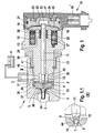
- Figure 1 shows a section through an inventively designed pressure control valve in one first embodiment.
- a pressure control valve 1 closes the connection from a high-pressure fuel accumulator 2 to a low-pressure line 3, which is connected to a fuel tank 4 is, or releases.
- the pressure regulating valve 1 comprises a valve piece 5, in which a central bore 6 is received.
- the bore 6 enters a throttle point. 7 over, which ends in a cone 8.
- the centrally arranged in the valve piece 5 bore 6th is closed with a closing element 9, which is designed here as a valve ball, by placing the closing element 9 in a sealing seat 10 in the cone 8.
- the closing element 9 in addition to the spherical closure element 9 shown in Figure 1, which by means of a Valve piston 11 is guided, but not firmly connected to the valve piston 11, can the closing element 9 also be firmly connected to the valve piston 11 and, for example be formed as a spherical or conical termination of the valve piston 11. Also, instead of the seat valve shown here, a slide valve or flat seat valve be used.
- the valve piston 11 is for controlling the closing element 9 in a guide 12 in one Valve housing 13 out.
- the Valve piston 11 On its side facing away from the closing element 9 is the Valve piston 11 is provided with an anchor plate 14.
- the armature plate 14 of the magnetic coil 15 When energizing one in the valve housing 13 recorded magnetic coil 15, the armature plate 14 of the magnetic coil 15 attracted.
- the valve piston 11 moves in the direction of the bore 6 in Valve piece 5 and provides the closing element 9 in its closing seat 10.
- the power supply the magnetic coil 15 via a cover 16, in a preferably from Plastic-made connector housing 17 is added.
- the electrical connection is made via connector pins 18.
- a liquid-tight connection of the connector housing 17 with the valve housing 13 is achieved in that between the valve housing 13th and the plug housing 17, a labyrinth seal 19 is formed.
- the connector housing 17 directly in an injection molding process the valve housing 13 injected.
- a closure piece 20 which closes the valve housing 13.
- a sealing ring 21 is arranged between the end piece 20 and the valve housing 13.
- the sealing ring 21 is preferably an O-ring, but it is also any further, known in the art Sealing ring.
- the end piece 20 is formed such that between the anchor plate 14 and the end piece 20 a cavity 22 is formed. At the same time serves the final piece 20 as a stop for Wegbegrenzung of the valve piston 11. For this purpose is between a first End face 24 of the anchor plate 14 and an end face 25 of the end piece 20 a gap 23 trained. The height of the gap 20 corresponds to that in the opening path of the valve piston 11th
- valve piston 11 moves in the direction of the end piece 20. This raises the closing element 9 from its sealing seat 10 and are via the bore 6 and the throttle point 7, the connection from the high-pressure accumulator 2 in the low pressure line 3 free.
- the opening process is by a spring element 26 supported, which in a valve piston 11 surrounding the spring chamber 27 is included.
- the spring element 26 is designed as a compression spring and is supported with one side on the second end face 28 of the anchor plate 14 and with the other side on an end face 29 of the spring chamber 27.
- the opening movement of the valve piston 11, with the anchor plate 14th is firmly connected, is stopped by that the first end face 24 of the anchor plate 14 at the end face 25 of the end piece 20 abuts.
- the opening stroke of the valve piston 11 is selected so that in a spherical closure member 9, which is preferably received freely movable, this is from its sealing seat 10th lifts, but can not leave the cone 8 past the valve piston 11 over its position.
- valve piston 11 On the side facing the closing element 9, the valve piston 11 is of a valve chamber 30 enclosed. From the valve chamber 30 extends a bore 31 through which the Valve chamber 30 is connected to the low pressure line 3.
- the valve piston 11 ends in a conical Termination 33.
- the conical termination 33 provided with a plane surface against which the closing element 9 is supported.
- the conical termination 33 in addition to the plane surface, the conical termination 33, as shown in Figure 1.1, also a dome 44, which receives the ball-shaped closing element 9.
- the closing element 9 In the germinal end 33 of the valve piston 11 with cap 44 is between the Calotte 44 and the closing element 9 is preferably formed an oil film. The by the Oil film resulting adhesion forces cause when opening the pressure control valve 1, the closing element 9 is pulled out of the closing seat 10 and so the connection between the high pressure accumulator 2 and the low pressure line 3 is opened safely.
- a filter element 34 is arranged.
- a spacer 35 between the valve piece 5 and the valve housing 13 is arranged.
- About the thickness of the spacer ring 35 can be the valve piece 5 position so that the closing element 9 with closed pressure control valve 1 in his closing seat 10 is provided, which emit no fuel from the high-pressure accumulator 2 can.
- the attachment of the spacer ring 35 and the valve member 5 in the valve housing 13 is preferably carried out by means of a crimping edge 36.
- a pressure and liquid-tight connection between the valve piece 5 and the housing 37 of the High-pressure accumulator 2 is achieved in that a biting edge 38 is formed on the valve piece 5 is.
- the valve piece 5 is with the biting edge 38 against the housing 37 of the high-pressure accumulator 2 pressed.
- the valve housing 13 with a threaded sleeve 39th screwed in the housing 37 of the high-pressure accumulator 2.
- the necessary contact pressure, the is required to a duck-tight connection between the valve piece 5 and the housing 37 of the high pressure accumulator 2 is achieved by a valve housing in the 13th reached snap ring 40 reached.
- the threaded sleeve 39 presses against the snap ring 40, whereby the valve housing 13 is guided in the direction of the high-pressure accumulator 2 becomes.
- a high pressure accumulator 2 acting on the pressure control valve 1 leads Compressive force or an externally applied to the pressure control valve 1 tensile force to that the snap ring 40 is pressed against the threaded sleeve 39.
- Threaded sleeve 39 frictionally connected to the housing 37 of the high-pressure accumulator 2, so that when acting in the direction of the threaded sleeve 39 force on the snap ring 40 of the snap ring 40 and thus the valve housing 13 is held in position becomes.
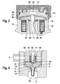
- FIG. 2 shows a section through a second embodiment of an invention formed pressure control valve.
- the spring element 42 is wound as a conical Spiral spring formed. With one side, the spring element 42 is supported against the Stage 32 in the valve piston 11, with the other side against the valve piece 5.
- the spring element 42 is formed as a compression spring, so that it helps to open the pressure control valve 1 works.
- the opening stroke of the valve piston 11 is also limited by the fact that the first Front side 24 of the anchor plate 14 abuts against the end face 25 of the end piece 20.
- the width of the gap 23 between the anchor plate 14 and the end piece 20 corresponds while the distance traveled by the valve piston 11 path length. Again, the path is chosen so that the loosely received in the cone 8 of the valve piece 5 spherical trained closing element 9 can not fall out of the cone 8.
- the closing element 9 is preferably by means of a plan ground end face of the conical end 33 of the valve cone 11 in the sealing seat 10 made.
- the closing surface be designed in the form of a cap 44 (see Figure 1.1), which is the spherically shaped Closing element 9 receives.
- the cap 44 an oil film, so that the ball-shaped closing element 9 due to the resulting Adphases concept pulled when opening the pressure control valve 1 from its sealing seat 10 becomes.
- FIG. 3 is a section of a pressure regulating valve according to the invention a further embodiment can be removed.
- the spring element 26 in shape a plate spring formed.
- the trained as a plate spring spring element 26 is in the The spring chamber 27 surrounding the valve piston 11 faces on the armature plate 14 Page arranged.
- the spring element 26 is supported with one side against the end face 29th the spring chamber 27 from and with the other side against the second end face 28 of the anchor plate 14.
- the trained as a plate spring spring element 26 also acts here as a compression spring supportive when opening the pressure control valve 1.
- the plate spring shown in Figure 3 can also be a helical compression spring, a plate spring package or any spring element 26 Any other known to those skilled spring geometry, which use as a compression spring leaves, can be used.
- FIG. 4 shows a further embodiment of a pressure regulating valve designed according to the invention.
- a cylindrically wound coil spring 42 used in place of the conically wound coil spring shown in Figure 2 as a spring element 42 in the embodiment shown in Figure 4, a cylindrically wound coil spring 42 used.
- the spring element 42 designed as a cylindrically wound spiral spring is supported with one side against the valve piece 5 and with the other side against a Ring 43, which rests on the step 32 of the valve piston 11.
- a cylindrical wound coil spring as spring element 42, it is also possible in place of the ring 43 form a rib on the valve piston 11, against which the spring element 42nd supported.
- a spring element 42 which as a conical screw compression spring is formed from a strip of rectangular cross-section.
- a spring element 42 which as a conical screw compression spring is formed from a strip of rectangular cross-section.
- the spring elements 42 shown in Figures 2 and 4 in the form of conical or cylindrical wound coil springs and disc springs or a disc spring package to use.
- any further known to the expert form of a compression spring can be used as a spring element 42.
- the pressure control valve 1 can be next to the actuator described above in the form of an electromagnet also a piezo actuator or a hydraulic / mechanical Insert the actuator.
Landscapes
- Engineering & Computer Science (AREA)
- General Engineering & Computer Science (AREA)
- Mechanical Engineering (AREA)
- Physics & Mathematics (AREA)
- Fluid Mechanics (AREA)
- Chemical & Material Sciences (AREA)
- Combustion & Propulsion (AREA)
- General Physics & Mathematics (AREA)
- Automation & Control Theory (AREA)
- Safety Valves (AREA)
- Fuel-Injection Apparatus (AREA)
Applications Claiming Priority (2)
| Application Number | Priority Date | Filing Date | Title |
|---|---|---|---|
| DE102004002964A DE102004002964A1 (de) | 2004-01-21 | 2004-01-21 | Druckregelventil für einen Hochdruckspeicher einer Verbrennungskraftmaschine |
| DE102004002964 | 2004-01-21 |
Publications (2)
| Publication Number | Publication Date |
|---|---|
| EP1557597A1 true EP1557597A1 (fr) | 2005-07-27 |
| EP1557597B1 EP1557597B1 (fr) | 2012-01-11 |
Family
ID=34625729
Family Applications (1)
| Application Number | Title | Priority Date | Filing Date |
|---|---|---|---|
| EP04028091A Expired - Lifetime EP1557597B1 (fr) | 2004-01-21 | 2004-11-26 | Soupape de régulation de pression d'une rampe commune d'un moteur à combustion interne |
Country Status (2)
| Country | Link |
|---|---|
| EP (1) | EP1557597B1 (fr) |
| DE (1) | DE102004002964A1 (fr) |
Cited By (12)
| Publication number | Priority date | Publication date | Assignee | Title |
|---|---|---|---|---|
| WO2006100141A1 (fr) * | 2005-03-21 | 2006-09-28 | Robert Bosch Gmbh | Dispositif d'injection de carburant pour moteur a combustion interne |
| FR2899949A1 (fr) * | 2006-04-13 | 2007-10-19 | Eaton Sa Monegasque | Electrovanne de regulation de pression |
| WO2008058952A1 (fr) * | 2006-11-14 | 2008-05-22 | Hydraulik-Ring Gmbh | Système de carburant haute pression avec compensation de volume, en particulier pour la phase de refroidissement du système haute pression |
| WO2009080426A1 (fr) * | 2007-12-21 | 2009-07-02 | Robert Bosch Gmbh | Soupape de régulation de pression pour réguler la pression dans un réservoir de carburant à haute pression |
| FR2973092A1 (fr) * | 2011-03-25 | 2012-09-28 | Bosch Gmbh Robert | Dispositif d'obturation, regulateur de pression comportant un tel dispositif, dispositif d'injection diesel comportant un tel regulateur, moteur diesel et vehicule comportant un tel moteur |
| EP2535554A1 (fr) * | 2011-06-15 | 2012-12-19 | Delphi Technologies Holding S.à.r.l. | Soupape électrique pour décharger un rail commun |
| FR3002003A1 (fr) * | 2013-02-11 | 2014-08-15 | Bosch Gmbh Robert | Procede de realisation d'une soupape a commande electromagnetique |
| CN104169567A (zh) * | 2012-03-15 | 2014-11-26 | 罗伯特·博世有限公司 | 用于调整内燃机高压燃料贮存器中压力的调压阀 |
| CN104781545A (zh) * | 2012-09-17 | 2015-07-15 | 罗伯特·博世有限公司 | 用于燃料喷射系统的压力调节阀 |
| WO2015149965A1 (fr) * | 2014-03-31 | 2015-10-08 | Robert Bosch Gmbh | Vanne de régulation de pression pour un accumulateur haute pression |
| WO2015183423A1 (fr) * | 2014-05-29 | 2015-12-03 | Caterpillar Inc. | Ensemble filtre et limiteur de débit pour système de carburant d'un moteur |
| CN104364510B (zh) * | 2012-05-31 | 2017-11-28 | 罗伯特·博世有限公司 | 压力调节阀 |
Families Citing this family (7)
| Publication number | Priority date | Publication date | Assignee | Title |
|---|---|---|---|---|
| DE102010043092A1 (de) | 2010-10-29 | 2012-05-03 | Robert Bosch Gmbh | Druckregelventil |
| DE102010043097A1 (de) | 2010-10-29 | 2012-05-03 | Robert Bosch Gmbh | Druckregelventil |
| DE102011105586B4 (de) * | 2011-06-27 | 2014-12-24 | Staiger Gmbh & Co. Kg | Ventil |
| DE102012221157A1 (de) | 2012-11-20 | 2014-05-22 | Robert Bosch Gmbh | Druckregelventil für einen Hochdruckspeicher eines Verbrennungsmotors |
| DE102013200634B4 (de) | 2013-01-17 | 2024-03-28 | Robert Bosch Gmbh | Druckregelventil für einen Kraftstoff-Hochdruckspeicher |
| DE102014202278A1 (de) | 2014-02-07 | 2015-08-13 | Robert Bosch Gmbh | Druckregelventil für einen Hochdruckspeicher |
| DE102015205114B4 (de) | 2015-03-20 | 2022-08-04 | Volkswagen Aktiengesellschaft | Verfahren zur Vermeidung zu hoher Systemdrücke in Common-Rail-Systemen |
Citations (9)
| Publication number | Priority date | Publication date | Assignee | Title |
|---|---|---|---|---|
| EP0243871A2 (fr) * | 1986-05-02 | 1987-11-04 | Nippondenso Co., Ltd. | Système d'injection de carburant |
| EP0267162A2 (fr) | 1986-11-07 | 1988-05-11 | ELASIS SISTEMA RICERCA FIAT NEL MEZZOGIORNO Società Consortile per Azioni | Electrovannes régulant la pression, notamment pour circuits à haute pression pour systèmes d'injection de machines à combustion interne |
| US4905960A (en) * | 1988-12-08 | 1990-03-06 | Cummins Engine Company, Inc. | Solenoid valve stroke adjustment locking mechanism and method of forming the same |
| US5413308A (en) * | 1993-09-03 | 1995-05-09 | The Horton Company | Fail-open solenoid actuated valve |
| EP0990791A1 (fr) * | 1998-09-29 | 2000-04-05 | Eaton | Electrovanne de régulation de pression |
| DE19952774A1 (de) * | 1999-11-03 | 2001-05-23 | Daimler Chrysler Ag | Vorrichtung zum Ablassen von Fluid aus einem System |
| US20030057394A1 (en) * | 2001-09-26 | 2003-03-27 | Tadaaki Makino | Electromagnetic fluid control device having magnetostrictive member |
| DE10236314A1 (de) * | 2001-09-08 | 2003-04-03 | Bosch Gmbh Robert | Einspritzanlage für Brennkraftmaschinen mit verbesserten Starteigenschaften |
| DE10257663A1 (de) * | 2001-12-11 | 2003-07-17 | Denso Corp | Commen-Rail-Kraftstoffeinspritzsystem mit einem normal offenen elektromagnetischen Ventil |
-
2004
- 2004-01-21 DE DE102004002964A patent/DE102004002964A1/de not_active Withdrawn
- 2004-11-26 EP EP04028091A patent/EP1557597B1/fr not_active Expired - Lifetime
Patent Citations (9)
| Publication number | Priority date | Publication date | Assignee | Title |
|---|---|---|---|---|
| EP0243871A2 (fr) * | 1986-05-02 | 1987-11-04 | Nippondenso Co., Ltd. | Système d'injection de carburant |
| EP0267162A2 (fr) | 1986-11-07 | 1988-05-11 | ELASIS SISTEMA RICERCA FIAT NEL MEZZOGIORNO Società Consortile per Azioni | Electrovannes régulant la pression, notamment pour circuits à haute pression pour systèmes d'injection de machines à combustion interne |
| US4905960A (en) * | 1988-12-08 | 1990-03-06 | Cummins Engine Company, Inc. | Solenoid valve stroke adjustment locking mechanism and method of forming the same |
| US5413308A (en) * | 1993-09-03 | 1995-05-09 | The Horton Company | Fail-open solenoid actuated valve |
| EP0990791A1 (fr) * | 1998-09-29 | 2000-04-05 | Eaton | Electrovanne de régulation de pression |
| DE19952774A1 (de) * | 1999-11-03 | 2001-05-23 | Daimler Chrysler Ag | Vorrichtung zum Ablassen von Fluid aus einem System |
| DE10236314A1 (de) * | 2001-09-08 | 2003-04-03 | Bosch Gmbh Robert | Einspritzanlage für Brennkraftmaschinen mit verbesserten Starteigenschaften |
| US20030057394A1 (en) * | 2001-09-26 | 2003-03-27 | Tadaaki Makino | Electromagnetic fluid control device having magnetostrictive member |
| DE10257663A1 (de) * | 2001-12-11 | 2003-07-17 | Denso Corp | Commen-Rail-Kraftstoffeinspritzsystem mit einem normal offenen elektromagnetischen Ventil |
Cited By (20)
| Publication number | Priority date | Publication date | Assignee | Title |
|---|---|---|---|---|
| WO2006100141A1 (fr) * | 2005-03-21 | 2006-09-28 | Robert Bosch Gmbh | Dispositif d'injection de carburant pour moteur a combustion interne |
| US7574297B2 (en) | 2005-03-21 | 2009-08-11 | Robert Bosch Gmbh | Fuel injection device for an internal combustion engine |
| FR2899949A1 (fr) * | 2006-04-13 | 2007-10-19 | Eaton Sa Monegasque | Electrovanne de regulation de pression |
| WO2007119007A1 (fr) * | 2006-04-13 | 2007-10-25 | Borgwarner Inc. | Electrovanne de regulation de pression |
| WO2008058952A1 (fr) * | 2006-11-14 | 2008-05-22 | Hydraulik-Ring Gmbh | Système de carburant haute pression avec compensation de volume, en particulier pour la phase de refroidissement du système haute pression |
| WO2009080426A1 (fr) * | 2007-12-21 | 2009-07-02 | Robert Bosch Gmbh | Soupape de régulation de pression pour réguler la pression dans un réservoir de carburant à haute pression |
| US8826889B2 (en) | 2007-12-21 | 2014-09-09 | Robert Bosch Gmbh | Pressure regulating valve for regulating the pressure in a high-pressure reservoir |
| FR2973092A1 (fr) * | 2011-03-25 | 2012-09-28 | Bosch Gmbh Robert | Dispositif d'obturation, regulateur de pression comportant un tel dispositif, dispositif d'injection diesel comportant un tel regulateur, moteur diesel et vehicule comportant un tel moteur |
| JP2014518344A (ja) * | 2011-06-15 | 2014-07-28 | デルファイ・テクノロジーズ・ホールディング・エス.アー.エール.エル. | コモンレール排出のため電磁弁 |
| CN103703240A (zh) * | 2011-06-15 | 2014-04-02 | 德尔福技术控股有限公司 | 用于排放共轨的电阀 |
| WO2012171948A1 (fr) * | 2011-06-15 | 2012-12-20 | Delphi Technologies Holding S.À.R.L. | Électrovanne de décharge de rampe commune à haute pression |
| EP2535554A1 (fr) * | 2011-06-15 | 2012-12-19 | Delphi Technologies Holding S.à.r.l. | Soupape électrique pour décharger un rail commun |
| US9297472B2 (en) | 2011-06-15 | 2016-03-29 | Delphi International Operations Luxembourg S.A.R.L. | Electro-valve for discharging common rail |
| CN103703240B (zh) * | 2011-06-15 | 2016-08-17 | 德尔福国际运营卢森堡有限公司 | 用于排放共轨的电阀 |
| CN104169567A (zh) * | 2012-03-15 | 2014-11-26 | 罗伯特·博世有限公司 | 用于调整内燃机高压燃料贮存器中压力的调压阀 |
| CN104364510B (zh) * | 2012-05-31 | 2017-11-28 | 罗伯特·博世有限公司 | 压力调节阀 |
| CN104781545A (zh) * | 2012-09-17 | 2015-07-15 | 罗伯特·博世有限公司 | 用于燃料喷射系统的压力调节阀 |
| FR3002003A1 (fr) * | 2013-02-11 | 2014-08-15 | Bosch Gmbh Robert | Procede de realisation d'une soupape a commande electromagnetique |
| WO2015149965A1 (fr) * | 2014-03-31 | 2015-10-08 | Robert Bosch Gmbh | Vanne de régulation de pression pour un accumulateur haute pression |
| WO2015183423A1 (fr) * | 2014-05-29 | 2015-12-03 | Caterpillar Inc. | Ensemble filtre et limiteur de débit pour système de carburant d'un moteur |
Also Published As
| Publication number | Publication date |
|---|---|
| DE102004002964A1 (de) | 2005-08-11 |
| EP1557597B1 (fr) | 2012-01-11 |
Similar Documents
| Publication | Publication Date | Title |
|---|---|---|
| EP1557597B1 (fr) | Soupape de régulation de pression d'une rampe commune d'un moteur à combustion interne | |
| EP1492954B1 (fr) | Soupape reglable de regulation de pression pour systemes d'injection de carburant | |
| EP2016278B1 (fr) | Régulateur de pression avec fonction de circulation de secours et de purge | |
| EP0657644A2 (fr) | Dispositif d'injection de combustible pour moteurs à combustion interne | |
| WO2009124852A1 (fr) | Pompe pour transporter un fluide | |
| DE102016220326A1 (de) | Ventil zum Zumessen eines gasförmigen oder flüssigen Kraftstoffs | |
| EP1092863A3 (fr) | Soupape de régulation de pression pour système d'injection de combustible à accumulation pour moteurs à combustion interne | |
| WO2014067729A1 (fr) | Actionneur | |
| DE102014214231A1 (de) | Elektromagnetische Stelleinheit für ein Saugventil sowie Saugventil | |
| DE102007011047A1 (de) | Magnetventilinjektor | |
| EP3387247B1 (fr) | Soupape d'admission à commande électromagnétique et pompe haute pression munie d'une soupape d'admission | |
| WO2001027463A1 (fr) | Injecteur pour systeme d'injection de carburant pour moteurs a combustion interne, muni d'un pointeau faisant saillie dans la chambre de commande de soupape | |
| DE102007001550A1 (de) | Injektor zum Einspritzen von Kraftstoff | |
| DE102012221157A1 (de) | Druckregelventil für einen Hochdruckspeicher eines Verbrennungsmotors | |
| DE102006041977A1 (de) | Injektor zum Einspritzen von Kraftstoff | |
| DE102013221484A1 (de) | Kraftstoffinjektor | |
| DE102013222483A1 (de) | Druckregelventil | |
| DE102020209574A1 (de) | Elektromagnetisch betätigbares Einlassventil und Hochdruckpumpe mit Einlassventil | |
| EP3365551A1 (fr) | Soupape d'admission à commande électromagnétique et pompe haute pression munie d'une soupape d'admission | |
| DE102016206261A1 (de) | Kraftstoffinjektor | |
| EP3056725B1 (fr) | Systeme de vanne de commande | |
| DE3410431A1 (de) | Elektromagnetisch zu betaetigendes fluidsteuerventil | |
| WO2019197067A1 (fr) | Soupape d'admission à commande électromagnétique et pompe haute pression munie d'une soupape d'admission | |
| DE102018219233A1 (de) | Elektromagnetisch betätigbares Einlassventil und Hochdruckpumpe mit Einlassventil | |
| DE102013212231A1 (de) | Kraftstoffinjektor für ein Hochdruckeinspritzsystem |
Legal Events
| Date | Code | Title | Description |
|---|---|---|---|
| PUAI | Public reference made under article 153(3) epc to a published international application that has entered the european phase |
Free format text: ORIGINAL CODE: 0009012 |
|
| AK | Designated contracting states |
Kind code of ref document: A1 Designated state(s): AT BE BG CH CY CZ DE DK EE ES FI FR GB GR HU IE IS IT LI LU MC NL PL PT RO SE SI SK TR |
|
| AX | Request for extension of the european patent |
Extension state: AL HR LT LV MK YU |
|
| AKX | Designation fees paid | ||
| 17P | Request for examination filed |
Effective date: 20060420 |
|
| RBV | Designated contracting states (corrected) |
Designated state(s): DE FR GB IT |
|
| RIN1 | Information on inventor provided before grant (corrected) |
Inventor name: SCHOEGGL, FRANK Inventor name: SCHEURER, HANS-PETER Inventor name: BEUCHE, VOLKER Inventor name: ZERLE, LORENZ Inventor name: BUSCH, ROGER |
|
| 17Q | First examination report despatched |
Effective date: 20100322 |
|
| GRAP | Despatch of communication of intention to grant a patent |
Free format text: ORIGINAL CODE: EPIDOSNIGR1 |
|
| GRAS | Grant fee paid |
Free format text: ORIGINAL CODE: EPIDOSNIGR3 |
|
| GRAA | (expected) grant |
Free format text: ORIGINAL CODE: 0009210 |
|
| AK | Designated contracting states |
Kind code of ref document: B1 Designated state(s): DE FR GB IT |
|
| REG | Reference to a national code |
Ref country code: GB Ref legal event code: FG4D Free format text: NOT ENGLISH |
|
| REG | Reference to a national code |
Ref country code: DE Ref legal event code: R096 Ref document number: 502004013214 Country of ref document: DE Effective date: 20120308 |
|
| PLBE | No opposition filed within time limit |
Free format text: ORIGINAL CODE: 0009261 |
|
| STAA | Information on the status of an ep patent application or granted ep patent |
Free format text: STATUS: NO OPPOSITION FILED WITHIN TIME LIMIT |
|
| 26N | No opposition filed |
Effective date: 20121012 |
|
| REG | Reference to a national code |
Ref country code: DE Ref legal event code: R097 Ref document number: 502004013214 Country of ref document: DE Effective date: 20121012 |
|
| PGFP | Annual fee paid to national office [announced via postgrant information from national office to epo] |
Ref country code: GB Payment date: 20121122 Year of fee payment: 9 Ref country code: IT Payment date: 20121126 Year of fee payment: 9 |
|
| GBPC | Gb: european patent ceased through non-payment of renewal fee |
Effective date: 20131126 |
|
| PG25 | Lapsed in a contracting state [announced via postgrant information from national office to epo] |
Ref country code: IT Free format text: LAPSE BECAUSE OF NON-PAYMENT OF DUE FEES Effective date: 20131126 |
|
| PG25 | Lapsed in a contracting state [announced via postgrant information from national office to epo] |
Ref country code: GB Free format text: LAPSE BECAUSE OF NON-PAYMENT OF DUE FEES Effective date: 20131126 |
|
| REG | Reference to a national code |
Ref country code: FR Ref legal event code: PLFP Year of fee payment: 12 |
|
| PGFP | Annual fee paid to national office [announced via postgrant information from national office to epo] |
Ref country code: FR Payment date: 20151124 Year of fee payment: 12 |
|
| REG | Reference to a national code |
Ref country code: FR Ref legal event code: ST Effective date: 20170731 |
|
| PG25 | Lapsed in a contracting state [announced via postgrant information from national office to epo] |
Ref country code: FR Free format text: LAPSE BECAUSE OF NON-PAYMENT OF DUE FEES Effective date: 20161130 |
|
| PGFP | Annual fee paid to national office [announced via postgrant information from national office to epo] |
Ref country code: DE Payment date: 20240123 Year of fee payment: 20 |
|
| REG | Reference to a national code |
Ref country code: DE Ref legal event code: R071 Ref document number: 502004013214 Country of ref document: DE |