EP1559960B1 - Système pour la climatisation des bâtiments - Google Patents
Système pour la climatisation des bâtiments Download PDFInfo
- Publication number
- EP1559960B1 EP1559960B1 EP05001792A EP05001792A EP1559960B1 EP 1559960 B1 EP1559960 B1 EP 1559960B1 EP 05001792 A EP05001792 A EP 05001792A EP 05001792 A EP05001792 A EP 05001792A EP 1559960 B1 EP1559960 B1 EP 1559960B1
- Authority
- EP
- European Patent Office
- Prior art keywords
- construction element
- enveloping bodies
- storage material
- arrangement according
- carrier medium
- Prior art date
- Legal status (The legal status is an assumption and is not a legal conclusion. Google has not performed a legal analysis and makes no representation as to the accuracy of the status listed.)
- Expired - Lifetime
Links
- 239000011232 storage material Substances 0.000 claims abstract description 38
- 238000010276 construction Methods 0.000 claims description 22
- 239000000463 material Substances 0.000 claims description 15
- 238000005338 heat storage Methods 0.000 claims description 13
- 238000010438 heat treatment Methods 0.000 claims description 11
- 238000002844 melting Methods 0.000 claims description 11
- 230000008018 melting Effects 0.000 claims description 11
- 238000001816 cooling Methods 0.000 claims description 10
- 239000002184 metal Substances 0.000 claims description 3
- 238000004378 air conditioning Methods 0.000 description 7
- 230000005611 electricity Effects 0.000 description 6
- 230000000694 effects Effects 0.000 description 5
- 230000008901 benefit Effects 0.000 description 4
- 239000002826 coolant Substances 0.000 description 4
- QTBSBXVTEAMEQO-UHFFFAOYSA-N Acetic acid Chemical compound CC(O)=O QTBSBXVTEAMEQO-UHFFFAOYSA-N 0.000 description 3
- PEDCQBHIVMGVHV-UHFFFAOYSA-N Glycerine Chemical compound OCC(O)CO PEDCQBHIVMGVHV-UHFFFAOYSA-N 0.000 description 3
- 239000004566 building material Substances 0.000 description 3
- 230000006399 behavior Effects 0.000 description 2
- 239000012530 fluid Substances 0.000 description 2
- DCAYPVUWAIABOU-UHFFFAOYSA-N hexadecane Chemical compound CCCCCCCCCCCCCCCC DCAYPVUWAIABOU-UHFFFAOYSA-N 0.000 description 2
- 239000003094 microcapsule Substances 0.000 description 2
- 238000001179 sorption measurement Methods 0.000 description 2
- AKEJUJNQAAGONA-UHFFFAOYSA-N sulfur trioxide Chemical compound O=S(=O)=O AKEJUJNQAAGONA-UHFFFAOYSA-N 0.000 description 2
- 229910021536 Zeolite Inorganic materials 0.000 description 1
- 238000010521 absorption reaction Methods 0.000 description 1
- 230000015572 biosynthetic process Effects 0.000 description 1
- 230000001143 conditioned effect Effects 0.000 description 1
- 239000004020 conductor Substances 0.000 description 1
- 230000001419 dependent effect Effects 0.000 description 1
- HNPSIPDUKPIQMN-UHFFFAOYSA-N dioxosilane;oxo(oxoalumanyloxy)alumane Chemical compound O=[Si]=O.O=[Al]O[Al]=O HNPSIPDUKPIQMN-UHFFFAOYSA-N 0.000 description 1
- 238000005516 engineering process Methods 0.000 description 1
- 230000006870 function Effects 0.000 description 1
- 239000007788 liquid Substances 0.000 description 1
- 230000003446 memory effect Effects 0.000 description 1
- 238000000034 method Methods 0.000 description 1
- 150000003839 salts Chemical class 0.000 description 1
- 238000007789 sealing Methods 0.000 description 1
- 230000001932 seasonal effect Effects 0.000 description 1
- 239000002689 soil Substances 0.000 description 1
- 239000007787 solid Substances 0.000 description 1
- 238000007711 solidification Methods 0.000 description 1
- 230000008023 solidification Effects 0.000 description 1
- 125000006850 spacer group Chemical group 0.000 description 1
- 239000000126 substance Substances 0.000 description 1
- 239000010457 zeolite Substances 0.000 description 1
Images

Classifications
-
- F—MECHANICAL ENGINEERING; LIGHTING; HEATING; WEAPONS; BLASTING
- F24—HEATING; RANGES; VENTILATING
- F24F—AIR-CONDITIONING; AIR-HUMIDIFICATION; VENTILATION; USE OF AIR CURRENTS FOR SCREENING
- F24F5/00—Air-conditioning systems or apparatus not covered by F24F1/00 or F24F3/00, e.g. using solar heat or combined with household units such as an oven or water heater
- F24F5/0089—Systems using radiation from walls or panels
-
- F—MECHANICAL ENGINEERING; LIGHTING; HEATING; WEAPONS; BLASTING
- F24—HEATING; RANGES; VENTILATING
- F24D—DOMESTIC- OR SPACE-HEATING SYSTEMS, e.g. CENTRAL HEATING SYSTEMS; DOMESTIC HOT-WATER SUPPLY SYSTEMS; ELEMENTS OR COMPONENTS THEREFOR
- F24D11/00—Central heating systems using heat accumulated in storage masses
- F24D11/002—Central heating systems using heat accumulated in storage masses water heating system
-
- F—MECHANICAL ENGINEERING; LIGHTING; HEATING; WEAPONS; BLASTING
- F24—HEATING; RANGES; VENTILATING
- F24D—DOMESTIC- OR SPACE-HEATING SYSTEMS, e.g. CENTRAL HEATING SYSTEMS; DOMESTIC HOT-WATER SUPPLY SYSTEMS; ELEMENTS OR COMPONENTS THEREFOR
- F24D3/00—Hot-water central heating systems
- F24D3/12—Tube and panel arrangements for ceiling, wall, or underfloor heating
- F24D3/14—Tube and panel arrangements for ceiling, wall, or underfloor heating incorporated in a ceiling, wall or floor
-
- F—MECHANICAL ENGINEERING; LIGHTING; HEATING; WEAPONS; BLASTING
- F24—HEATING; RANGES; VENTILATING
- F24F—AIR-CONDITIONING; AIR-HUMIDIFICATION; VENTILATION; USE OF AIR CURRENTS FOR SCREENING
- F24F5/00—Air-conditioning systems or apparatus not covered by F24F1/00 or F24F3/00, e.g. using solar heat or combined with household units such as an oven or water heater
- F24F5/0007—Air-conditioning systems or apparatus not covered by F24F1/00 or F24F3/00, e.g. using solar heat or combined with household units such as an oven or water heater cooling apparatus specially adapted for use in air-conditioning
- F24F5/0017—Air-conditioning systems or apparatus not covered by F24F1/00 or F24F3/00, e.g. using solar heat or combined with household units such as an oven or water heater cooling apparatus specially adapted for use in air-conditioning using cold storage bodies, e.g. ice
-
- F—MECHANICAL ENGINEERING; LIGHTING; HEATING; WEAPONS; BLASTING
- F24—HEATING; RANGES; VENTILATING
- F24F—AIR-CONDITIONING; AIR-HUMIDIFICATION; VENTILATION; USE OF AIR CURRENTS FOR SCREENING
- F24F5/00—Air-conditioning systems or apparatus not covered by F24F1/00 or F24F3/00, e.g. using solar heat or combined with household units such as an oven or water heater
- F24F5/0089—Systems using radiation from walls or panels
- F24F5/0092—Systems using radiation from walls or panels ceilings, e.g. cool ceilings
-
- Y—GENERAL TAGGING OF NEW TECHNOLOGICAL DEVELOPMENTS; GENERAL TAGGING OF CROSS-SECTIONAL TECHNOLOGIES SPANNING OVER SEVERAL SECTIONS OF THE IPC; TECHNICAL SUBJECTS COVERED BY FORMER USPC CROSS-REFERENCE ART COLLECTIONS [XRACs] AND DIGESTS
- Y02—TECHNOLOGIES OR APPLICATIONS FOR MITIGATION OR ADAPTATION AGAINST CLIMATE CHANGE
- Y02B—CLIMATE CHANGE MITIGATION TECHNOLOGIES RELATED TO BUILDINGS, e.g. HOUSING, HOUSE APPLIANCES OR RELATED END-USER APPLICATIONS
- Y02B30/00—Energy efficient heating, ventilation or air conditioning [HVAC]
-
- Y—GENERAL TAGGING OF NEW TECHNOLOGICAL DEVELOPMENTS; GENERAL TAGGING OF CROSS-SECTIONAL TECHNOLOGIES SPANNING OVER SEVERAL SECTIONS OF THE IPC; TECHNICAL SUBJECTS COVERED BY FORMER USPC CROSS-REFERENCE ART COLLECTIONS [XRACs] AND DIGESTS
- Y02—TECHNOLOGIES OR APPLICATIONS FOR MITIGATION OR ADAPTATION AGAINST CLIMATE CHANGE
- Y02E—REDUCTION OF GREENHOUSE GAS [GHG] EMISSIONS, RELATED TO ENERGY GENERATION, TRANSMISSION OR DISTRIBUTION
- Y02E60/00—Enabling technologies; Technologies with a potential or indirect contribution to GHG emissions mitigation
- Y02E60/14—Thermal energy storage
Definitions
- the invention relates to an arrangement for air conditioning of buildings, comprising a provided within a space defining part of the building guide for a heat transfer medium, which is in heat transfer connection with a space to be cooled or heated Jardinbegrenzungs Structure, means for heating or cooling of the heat transfer medium, a conveyor for Conveying the heat transfer medium through the guide and arranged in the building part latent heat storage, the storage material is in heat transfer connection with the space boundary surface of the building part and the guide for the heat transfer medium, wherein the storage material is arranged in closed enveloping bodies.
- An air conditioning arrangement of the aforementioned type is for example from the WO-A-03064931 known.
- latent heat storage devices change their phase state due to the supply or removal of heat, without the temperature changing during the phase change.
- this effect is already being exploited in air-conditioning technology through the use of ice storage systems, which are located centrally in the air-conditioned building.
- the disadvantage of this ice storage is in addition to the additional space but in that their Nutztemperaturnievau with 0 ° C is quite far away from the operating temperatures of large-area cooling systems whose flow temperature is in the range of 16 to 18 ° C.
- the power consumption of the ice storage for uniform ice formation in the storage in addition to circulating pumps usually also bubblers are required, there is an additional use of energy not only during storage operation.
- thermochemical sorption a heat-storing floor heating known that works on the thermochemical sorption principle. It consists of a base layer in which heating guides for the working fluid and a storage mass formed by zeolite in granulated form are located, wherein the entire support layer is hermetically sealed by sealing layers.
- the working fluid is steam conducted through the heating ducts, which enters the storage mass via openings in the heating ducts, wherein the heat in the storage mass is thermochemically converted.
- the heat storage is discharged by releasing heat of adsorption. With the help of electrical heating conductors and an evacuation pump, the moisture can be removed from the storage mass again, wherein the storage mass is dried and recharged via the supply of Desorptionstage.
- Such an arrangement requires very complex construction measures.
- the invention has for its object to provide an arrangement of the type mentioned, which makes it possible to equalize the power requirements for the air conditioning of buildings throughout the day and thus to reduce electricity costs.
- a memory material is used whose melting point is between about 16 ° C and 20 ° C and thus in the vicinity of the desired room temperature.
- enveloping bodies are used in the form of spheres with a diameter which can be from 1 ⁇ (microcapsules) to 30 mm, preferably 20 to 25 mm.
- a bed of these balls is applied to a support surface of the soil over which screed material is then poured.
- the enveloping bodies can also be dummy tubes with a circular or polygonal cross-section into which the storage material is filled.
- Such blind tubes with a length of about 300 to 900 mm can also be embedded in the building material, but are particularly suitable for laying in hollow walls, ceilings or floors. They can be attached to laid in the building part planar support elements, as has long been known, for example, for Schuffen- or coolant tubes in surface heating.
- the dummy tubes can then be fastened alternately with such heating medium or coolant tubes to the same support elements.
- the enveloping bodies are in the form of flat cuboidal blocks and are attached to a flexible web, e.g. attached to a grid fleece, preferably in spaced rows, so that they can be inserted between the heat transfer medium lines leading.
- the enveloping bodies are plate-shaped and have on their outer side holders for the heat transfer medium leading lines. In this way, a good contact between the guides for the heat transfer medium and the latent heat storage is produced.
- the enveloping body may be made of plastic or metal.
- the invention further relates to a plate-shaped component for creating buildings, for example a wall, floor or ceiling element, which contains a guide for a heat transfer medium, which is in heat-transmitting connection with a space boundary surface of the component and is connectable to a conveyor for the heat transfer medium, wherein within the component a latent heat storage is arranged, the storage material is both with the space boundary surface and with the guide for the heat transfer medium in heat transfer connection, wherein the latent heat storage may be formed and arranged in the manner described above.
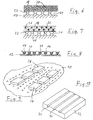
- Fig.1 shows a sample of a trained floor or a suitable for creating a floor element with a bottom 10, on which a support plate 12 rests, in the known manner, for example with retaining cam 13 lines 14 for guiding a heat transfer medium, ie a heating or cooling medium are attached. These lines 14 are covered by an intermediate layer 16 which is covered with a screed 18. In this screed plastic balls 20 are embedded, which contain the latent storage material.
- the Fig. 2 to 5 show different variants of the embodiment according to Fig. 1 , In the embodiment according to Fig. 2 eliminates the intermediate layer 16.
- the the The screed 20 containing screed material filled with the storage material also surrounds the lines 14 and the retaining cams 13.
- the lines 14 and the clamping cams 13 are covered by a first Estrichstrich 18 ', separated by an intermediate layer 21, the storage material containing balls 20 are.
- the layer formed from the balls 20 in turn is, separated by an intermediate layer 23, covered by a second screed layer 18 ".
- the embodiment according to Fig. 5 differs from the embodiment according to Fig. 4 in that the second separating or intermediate layer 23 is omitted and the layer formed from the balls 20 and the second screed layer 18 "coincide, ie the storage material is embedded in the second screed layer 18".
- Fig. 6 is different from that of Fig. 1 to 5 in that the heat transfer medium is not guided in lines, but that the cavity formed by spacer elements 22 between bottom 10 and intermediate layer 16 16 24 is used as a guide for the gaseous heat transfer medium, such as air.
- Fig. 7 corresponds to that of Fig. 6 with the exception that the storage material is not arranged in balls, but in dummy tubes 26, which are laid in the screed 18.
- the lines 14 for guiding a heat transfer medium and the storage material containing dummy tubes 26 are mounted alternately on the support plate 12.
- the lines and dummy tubes are inserted in clamping grooves, which are formed in the support plate 12.
- dummy tubes with a circular cross section and flat strip-shaped enveloping body can be used, but in principle can be laid in the same manner as the dummy tubes 26.
- Fig. 9 shows a further variant of the envelope material filled with the storage material.
- the enveloping bodies have the shape of flat cuboid blocks or platelets 28 with a base area of, for example, 25 ⁇ 30 mm.
- the platelets 28 are mounted in spaced rows on a nonwoven web 30.
- the grid fleece, together with the platelets attached to it, can be placed on an arrangement of lines such that the platelets each come to lie between the lines.
- a storage element with a plate-shaped hollow body 32, which contains the storage material and are formed in the clamping grooves 34, in which lines 14 for guiding a heat transfer medium can be inserted.
- These plate-shaped storage elements can now be laid in the building part in contact with the room boundary surface to be heated or cooled.
- the particular advantage of this embodiment lies in the direct contact between the lines for the heat transfer medium and the storage element. This solution is particularly suitable for chilled ceilings, since, unlike a floor area with a heat transfer screed, there is no other way to transfer heat between the active system and the store.
- suitable materials for component-integrated latent heat storage are, for example, short-chain paraphines (hexadecane and heptadekane), glycerol, sulfur trioxide, pure acetic acid, salts and other substances whose melting temperature is approximately between 16 and 20 ° C.
- a lower melting temperature would mean that a system flow temperature would have to be set to charge the memory, which would lead to a dew point below the surface to be cooled.
- Higher melting temperatures would have the consequence that the temperature difference between the melting memory material and the room temperature to be maintained would lead to a reduced discharge power and the cooling function would be too limited during the storage discharge.
- a system flow temperature is set so far below the melting temperature of the storage material that the storage material undergoes a phase change from liquid to solid. Since for the storage charge in practice, the room air conditioning is a much longer time than for the unloading available, the temperature must be only slightly below the melting or solidification temperature of the storage material directly on the outside of the memory. However, it must be taken into account that thermal conduction processes within the components and the associated temperature gradients within the structure result in additional temperature differences, which depend on the design of the construction. The closer the storage material is to the coolant-carrying lines and the better the heat transfer between the coolant and the storage material, the lower the temperature differences to be planned.
- the temperature in the storage material also increases until this material has reached its melting temperature.
- this condition is after a temperature rise reached by not more than 1 to 2 K, so that the cooling capacity of the space boundary surface has been reduced only slightly.
- the supply of further heat from the room to be conditioned is then taken up by the melting storage material without the temperature within the room boundary area increasing further. Only when the storage material has completely melted does the temperature rise within the structure.
Landscapes
- Engineering & Computer Science (AREA)
- General Engineering & Computer Science (AREA)
- Chemical & Material Sciences (AREA)
- Combustion & Propulsion (AREA)
- Mechanical Engineering (AREA)
- Sustainable Development (AREA)
- Life Sciences & Earth Sciences (AREA)
- Thermal Sciences (AREA)
- Physics & Mathematics (AREA)
- Building Environments (AREA)
- Central Heating Systems (AREA)
- Floor Finish (AREA)
- Air Conditioning Control Device (AREA)
- Duct Arrangements (AREA)
- Curing Cements, Concrete, And Artificial Stone (AREA)
Claims (32)
- Système de climatisation de bâtiments, ledit système comportant un guide (14, 24) destiné à un fluide caloporteur, qui est prévu à l'intérieur d'une pièce de bâtiment délimitant un espace et qui est en liaison de thermoconduction avec une surface de délimitation d'espace à refroidir ou à chauffer, un dispositif de chauffage ou de refroidissement du fluide caloporteur, un dispositif de transport du fluide caloporteur à travers le guide (14, 24), et un accumulateur de chaleur latente qui est disposé dans la pièce de bâtiment et dont le matériau accumulateur est en liaison de thermoconduction avec la surface de délimitation d'espace de la pièce de bâtiment et avec le guide (14, 24) destiné au fluide caloporteur, le matériau accumulateur étant disposé dans des corps d'enveloppe fermés (20, 26, 28), caractérisé en ce que les corps d'enveloppe contenant le matériau accumulateur sont disposés entre une première couche de ciment dans laquelle sont incorporées des conduites guidant le fluide caloporteur et une deuxième couche de ciment formant la surface de délimitation d'espace.
- Système selon la revendication 1, caractérisé en ce que la température de fusion du matériau accumulateur est située entre 16°C et 20°C environ.
- Système selon la revendication 1 ou 2, caractérisé en ce que les corps d'enveloppe (20, 26) qui contiennent le matériau accumulateur sont incorporés dans le matériau (18) qui forme la pièce de bâtiment.
- Système selon l'une des revendications 1 à 3, caractérisé en ce que les corps d'enveloppe contenant le matériau accumulateur entourent au moins partiellement des conduites qui enferment le fluide caloporteur.
- Système selon l'une des revendications 1 à 4, caractérisé en ce que les corps d'enveloppe sont des billes (20) d'un diamètre de 1 µm à 30 mm environ.
- Système selon l'une des revendications 1 à 5, caractérisé en ce que les corps d'enveloppe sont des tubes borgnes (26) de section circulaire ou polygonale.
- Système selon la revendication 6, caractérisé en ce que les tubes borgnes ont une longueur de 300 à 900 mm environ.
- Système selon la revendication 6 ou 7, caractérisé en ce que les tubes borgnes sont fixés à des éléments de support plans (12) montés dans la pièce de bâtiment.
- Système selon la revendication 8, caractérisé en ce que les tubes borgnes (26) sont maintenus au moyen de fixations de type agrafes conformées au niveau des éléments de support (12).
- Système selon la revendication 1, caractérisé en ce que les corps d'enveloppe (32) sont conformés en plaques, et possèdent sur leur côté extérieur des fixations (34) destinées à des conduites guidant le fluide caloporteur.
- Système selon la revendication 1, caractérisé en ce que les corps d'enveloppe ont la forme de parallélépipèdes plats (28).
- Système selon la revendication 11, caractérisé en ce que la surface de base des parallélépipèdes est de 25 x 30 mm environ.
- Système selon la revendication 11 ou 12, caractérisé en ce que les corps d'enveloppe contenant le matériau accumulateur sont fixés en rangées espacées à un panneau de matériau flexible (30).
- Système selon la revendication 13, caractérisé en ce que le panneau de matériau (30) est un matelas de fibres en treillis.
- Système selon l'une des revendications 1 à 14, caractérisé en ce que les corps d'enveloppe (20, 26, 28) sont en matière plastique.
- Système selon l'une des revendications 1 à 15, caractérisé en ce que les corps d'enveloppe (32) sont en métal.
- Élément de construction en forme de plaque destiné à la construction de bâtiments, caractérisé par un guide (14, 24) destiné à un fluide caloporteur, qui est en liaison de thermoconduction avec une surface de délimitation d'espace de l'élément de construction, et qui peut être raccordé à un dispositif de transport du fluide caloporteur, et par un accumulateur de chaleur latente qui est disposé à l'intérieur de l'élément de construction et dont le matériau accumulateur est en liaison de thermoconduction aussi bien avec la surface de délimitation d'espace qu'avec le guide destiné au fluide caloporteur, le matériau accumulateur étant disposé dans des corps d'enveloppe fermés (20, 26, 28), caractérisé en ce que les corps d'enveloppe contenant le matériau accumulateur sont disposés entre une première couche de ciment (18'), dans laquelle sont incorporées des conduites guidant le fluide caloporteur, et une deuxième couche de ciment (18'') qui forme la surface de délimitation d'espace.
- Élément de construction selon la revendication 17, caractérisé en ce que la température de fusion du matériau accumulateur est située entre 16°C et 20°C environ.
- Élément de construction selon la revendication 17 ou 18, caractérisé en ce que les corps d'enveloppe (20, 26) contenant le matériau accumulateur sont incorporés dans le matériau formant l'élément de construction.
- Élément de construction selon l'une des revendications 17 à 19, caractérisé en ce que les corps d'enveloppe (20) contenant le matériau accumulateur entourent au moins partiellement des conduites (14) guidant le fluide caloporteur.
- Élément de construction selon l'une des revendications 17 à 20, caractérisé en ce que les corps d'enveloppe sont des billes (20) d'un diamètre de 1 µm à 30 mm.
- Élément de construction selon l'une des revendications 17 à 20, caractérisé en ce que les corps d'enveloppe sont des tubes borgnes (26) de section circulaire ou polygonale.
- Élément de construction selon la revendication 22, caractérisé en ce que les tubes borgnes (26) ont une longueur de 300 à 900 mm environ.
- Élément de construction selon la revendication 22 ou 23, caractérisé en ce que les tubes borgnes (26) sont fixés à des éléments de support plans (12) montés dans l'élément de construction.
- Élément de construction selon la revendication 24, caractérisé en ce que les tubes borgnes (26) sont maintenus au moyen de fixations de type agrafes conformées au niveau des éléments de support (12).
- Élément selon la revendication 17, caractérisé en ce que les corps d'enveloppe (32) sont conformés en plaques, et possèdent sur leur côté extérieur des fixations (34) destinées à des conduites guidant le fluide caloporteur.
- Élément selon la revendication 17, caractérisé en ce que les corps d'enveloppe ont la forme de parallélépipèdes plats (28).
- Élément de construction selon la revendication 27, caractérisé en ce que la surface de base des parallélépipèdes est de 25 x 30 mm environ.
- Élément de construction selon la revendication 27 ou 28, caractérisé en ce que les corps d'enveloppe contenant le matériau accumulateur sont fixés en rangées espacées à un panneau de matériau flexible (30).
- Élément de construction selon la revendication 29, caractérisé en ce que le panneau de matériau (30) est un matelas de fibres en treillis.
- Élément de construction selon l'une des revendications 17 à 30, caractérisé en ce que les corps d'enveloppe sont en matière plastique.
- Élément de construction selon l'une des revendications 17 à 30, caractérisé en ce que les corps d'enveloppe sont en métal.
Priority Applications (1)
| Application Number | Priority Date | Filing Date | Title |
|---|---|---|---|
| PL05001792T PL1559960T3 (pl) | 2004-01-28 | 2005-01-28 | System klimatyzowania budynków |
Applications Claiming Priority (2)
| Application Number | Priority Date | Filing Date | Title |
|---|---|---|---|
| DE102004004322A DE102004004322A1 (de) | 2004-01-28 | 2004-01-28 | Anordnung zum Klimatisieren von Gebäuden |
| DE102004004322 | 2004-01-28 |
Publications (3)
| Publication Number | Publication Date |
|---|---|
| EP1559960A2 EP1559960A2 (fr) | 2005-08-03 |
| EP1559960A3 EP1559960A3 (fr) | 2006-05-17 |
| EP1559960B1 true EP1559960B1 (fr) | 2009-03-25 |
Family
ID=34638784
Family Applications (1)
| Application Number | Title | Priority Date | Filing Date |
|---|---|---|---|
| EP05001792A Expired - Lifetime EP1559960B1 (fr) | 2004-01-28 | 2005-01-28 | Système pour la climatisation des bâtiments |
Country Status (5)
| Country | Link |
|---|---|
| EP (1) | EP1559960B1 (fr) |
| AT (1) | ATE426781T1 (fr) |
| DE (2) | DE102004004322A1 (fr) |
| ES (1) | ES2325788T3 (fr) |
| PL (1) | PL1559960T3 (fr) |
Families Citing this family (4)
| Publication number | Priority date | Publication date | Assignee | Title |
|---|---|---|---|---|
| EP2519782A1 (fr) * | 2009-12-31 | 2012-11-07 | SGL Carbon SE | Élément de plafond ou de cloison comportant un registre de chauffage ou de refroidissement |
| CZ303841B6 (cs) * | 2012-02-14 | 2013-05-22 | Vysoké ucení technické v Brne | Tepelne akumulacní modul se systémem kapilárních rohozí a sestava z techto modulu |
| ES2421831B1 (es) * | 2012-03-05 | 2014-09-10 | Universidad De Valladolid | Elemento constructivo con integración de sistemas activos calefacción-refrigeración, en placas de yeso/elementos de trasdosado con materiales de cambio de fase incorporados |
| IT201600127185A1 (it) * | 2016-12-15 | 2018-06-15 | Rtp S R L S | Sistema di accumulo termico e climatizzazione di un ambiente |
Family Cites Families (3)
| Publication number | Priority date | Publication date | Assignee | Title |
|---|---|---|---|---|
| FR2794224B1 (fr) * | 1999-05-25 | 2001-08-17 | Acome Soc Coop Travailleurs | Dispositif de chauffage et/ou de rafraichissement de local |
| US20050040152A1 (en) * | 2002-02-01 | 2005-02-24 | Markus Koschenz | Thermoactive wall and ceiling element |
| DE20208898U1 (de) * | 2002-06-10 | 2002-10-02 | emcal Wärmesysteme GmbH, 48282 Emsdetten | Klimadecke mit PCM und dazu verwendbarer Beutel |
-
2004
- 2004-01-28 DE DE102004004322A patent/DE102004004322A1/de not_active Withdrawn
-
2005
- 2005-01-28 ES ES05001792T patent/ES2325788T3/es not_active Expired - Lifetime
- 2005-01-28 AT AT05001792T patent/ATE426781T1/de active
- 2005-01-28 EP EP05001792A patent/EP1559960B1/fr not_active Expired - Lifetime
- 2005-01-28 DE DE502005006914T patent/DE502005006914D1/de not_active Expired - Lifetime
- 2005-01-28 PL PL05001792T patent/PL1559960T3/pl unknown
Also Published As
| Publication number | Publication date |
|---|---|
| ATE426781T1 (de) | 2009-04-15 |
| DE502005006914D1 (de) | 2009-05-07 |
| ES2325788T3 (es) | 2009-09-17 |
| PL1559960T3 (pl) | 2009-10-30 |
| EP1559960A3 (fr) | 2006-05-17 |
| DE102004004322A1 (de) | 2005-08-11 |
| EP1559960A2 (fr) | 2005-08-03 |
Similar Documents
| Publication | Publication Date | Title |
|---|---|---|
| EP2519783B1 (fr) | Dispositif de thermorégulation d'une pièce | |
| EP2468977A1 (fr) | Elément conducteur de chaleur | |
| AT11439U1 (de) | Heizkörper mit latentwärmespeicher | |
| DE102008047768A1 (de) | Vorgefertigtes Verbundplattenelement zum Klimatisieren von Räumen | |
| EP1559960B1 (fr) | Système pour la climatisation des bâtiments | |
| DE102006029597A1 (de) | Klimadecke | |
| DE102012013624B4 (de) | Latentwärmespeichermodul und Hybridwärmespeicher | |
| DE102009017200A1 (de) | Wärmeaustauscher | |
| WO2023222539A1 (fr) | Panneau d'échangeur de chaleur pour réguler la température d'un espace | |
| WO2011104031A2 (fr) | Module d'accumulation de chaleur latente, dispositif de climatisation, ainsi que procédé de commande pour celui-ci | |
| EP4575327A2 (fr) | Composant | |
| DE102009004353A1 (de) | Vorrichtung und Verfahren zur Raumtemperierung und thermischen Raumkonditionierung | |
| WO2010099861A1 (fr) | Plafond climatisé | |
| DE102014200495A1 (de) | Fensterelement | |
| DE102007047750A1 (de) | Kühl-, Heiz- und Akustikplattenelement | |
| DE10019931C1 (de) | Aktives thermisches Bauelement | |
| EP3460351B1 (fr) | Appareil de conditionnement d'air mobile à accumulateur de chaleur latente | |
| WO2013124347A1 (fr) | Radiateur | |
| AT519899A1 (de) | Kühldeckenelement | |
| EP3296677A1 (fr) | Procédé de stockage de chaleur | |
| AT518992B1 (de) | Geschoßdecke | |
| DE19855594C1 (de) | Verfahren und Vorrichtung zum Homogenisieren von Temperaturen in gekühlten oder beheizten Baukörpern | |
| DE10051749A1 (de) | Montagebauelement mit integrierten Heiz-und/oder Kühlflächen sowie Verfahren zu seiner Herstellung | |
| DE102019124910A1 (de) | Profil, Gebäudelementanordung und Verwendung | |
| DE102019107756A1 (de) | Temperiervorrichtung |
Legal Events
| Date | Code | Title | Description |
|---|---|---|---|
| PUAI | Public reference made under article 153(3) epc to a published international application that has entered the european phase |
Free format text: ORIGINAL CODE: 0009012 |
|
| AK | Designated contracting states |
Kind code of ref document: A2 Designated state(s): AT BE BG CH CY CZ DE DK EE ES FI FR GB GR HU IE IS IT LI LT LU MC NL PL PT RO SE SI SK TR |
|
| AX | Request for extension of the european patent |
Extension state: AL BA HR LV MK YU |
|
| PUAL | Search report despatched |
Free format text: ORIGINAL CODE: 0009013 |
|
| AK | Designated contracting states |
Kind code of ref document: A3 Designated state(s): AT BE BG CH CY CZ DE DK EE ES FI FR GB GR HU IE IS IT LI LT LU MC NL PL PT RO SE SI SK TR |
|
| AX | Request for extension of the european patent |
Extension state: AL BA HR LV MK YU |
|
| 17P | Request for examination filed |
Effective date: 20061025 |
|
| AKX | Designation fees paid |
Designated state(s): AT BE BG CH CY CZ DE DK EE ES FI FR GB GR HU IE IS IT LI LT LU MC NL PL PT RO SE SI SK TR |
|
| 17Q | First examination report despatched |
Effective date: 20070314 |
|
| GRAP | Despatch of communication of intention to grant a patent |
Free format text: ORIGINAL CODE: EPIDOSNIGR1 |
|
| GRAS | Grant fee paid |
Free format text: ORIGINAL CODE: EPIDOSNIGR3 |
|
| GRAA | (expected) grant |
Free format text: ORIGINAL CODE: 0009210 |
|
| AK | Designated contracting states |
Kind code of ref document: B1 Designated state(s): AT BE BG CH CY CZ DE DK EE ES FI FR GB GR HU IE IS IT LI LT LU MC NL PL PT RO SE SI SK TR |
|
| REG | Reference to a national code |
Ref country code: GB Ref legal event code: FG4D Free format text: NOT ENGLISH |
|
| REG | Reference to a national code |
Ref country code: CH Ref legal event code: EP |
|
| REG | Reference to a national code |
Ref country code: IE Ref legal event code: FG4D Free format text: LANGUAGE OF EP DOCUMENT: GERMAN |
|
| REF | Corresponds to: |
Ref document number: 502005006914 Country of ref document: DE Date of ref document: 20090507 Kind code of ref document: P |
|
| REG | Reference to a national code |
Ref country code: GR Ref legal event code: EP Ref document number: 20090401157 Country of ref document: GR |
|
| REG | Reference to a national code |
Ref country code: CH Ref legal event code: NV Representative=s name: SCHNEIDER FELDMANN AG PATENT- UND MARKENANWAELTE |
|
| PG25 | Lapsed in a contracting state [announced via postgrant information from national office to epo] |
Ref country code: SI Free format text: LAPSE BECAUSE OF FAILURE TO SUBMIT A TRANSLATION OF THE DESCRIPTION OR TO PAY THE FEE WITHIN THE PRESCRIBED TIME-LIMIT Effective date: 20090325 Ref country code: FI Free format text: LAPSE BECAUSE OF FAILURE TO SUBMIT A TRANSLATION OF THE DESCRIPTION OR TO PAY THE FEE WITHIN THE PRESCRIBED TIME-LIMIT Effective date: 20090325 Ref country code: LT Free format text: LAPSE BECAUSE OF FAILURE TO SUBMIT A TRANSLATION OF THE DESCRIPTION OR TO PAY THE FEE WITHIN THE PRESCRIBED TIME-LIMIT Effective date: 20090325 |
|
| PG25 | Lapsed in a contracting state [announced via postgrant information from national office to epo] |
Ref country code: SE Free format text: LAPSE BECAUSE OF FAILURE TO SUBMIT A TRANSLATION OF THE DESCRIPTION OR TO PAY THE FEE WITHIN THE PRESCRIBED TIME-LIMIT Effective date: 20090625 |
|
| REG | Reference to a national code |
Ref country code: ES Ref legal event code: FG2A Ref document number: 2325788 Country of ref document: ES Kind code of ref document: T3 |
|
| REG | Reference to a national code |
Ref country code: IE Ref legal event code: FD4D |
|
| PG25 | Lapsed in a contracting state [announced via postgrant information from national office to epo] |
Ref country code: PT Free format text: LAPSE BECAUSE OF FAILURE TO SUBMIT A TRANSLATION OF THE DESCRIPTION OR TO PAY THE FEE WITHIN THE PRESCRIBED TIME-LIMIT Effective date: 20090901 Ref country code: EE Free format text: LAPSE BECAUSE OF FAILURE TO SUBMIT A TRANSLATION OF THE DESCRIPTION OR TO PAY THE FEE WITHIN THE PRESCRIBED TIME-LIMIT Effective date: 20090325 Ref country code: CZ Free format text: LAPSE BECAUSE OF FAILURE TO SUBMIT A TRANSLATION OF THE DESCRIPTION OR TO PAY THE FEE WITHIN THE PRESCRIBED TIME-LIMIT Effective date: 20090325 |
|
| REG | Reference to a national code |
Ref country code: PL Ref legal event code: T3 |
|
| PG25 | Lapsed in a contracting state [announced via postgrant information from national office to epo] |
Ref country code: IS Free format text: LAPSE BECAUSE OF FAILURE TO SUBMIT A TRANSLATION OF THE DESCRIPTION OR TO PAY THE FEE WITHIN THE PRESCRIBED TIME-LIMIT Effective date: 20090725 Ref country code: SK Free format text: LAPSE BECAUSE OF FAILURE TO SUBMIT A TRANSLATION OF THE DESCRIPTION OR TO PAY THE FEE WITHIN THE PRESCRIBED TIME-LIMIT Effective date: 20090325 Ref country code: RO Free format text: LAPSE BECAUSE OF FAILURE TO SUBMIT A TRANSLATION OF THE DESCRIPTION OR TO PAY THE FEE WITHIN THE PRESCRIBED TIME-LIMIT Effective date: 20090325 |
|
| PG25 | Lapsed in a contracting state [announced via postgrant information from national office to epo] |
Ref country code: DK Free format text: LAPSE BECAUSE OF FAILURE TO SUBMIT A TRANSLATION OF THE DESCRIPTION OR TO PAY THE FEE WITHIN THE PRESCRIBED TIME-LIMIT Effective date: 20090325 Ref country code: BG Free format text: LAPSE BECAUSE OF FAILURE TO SUBMIT A TRANSLATION OF THE DESCRIPTION OR TO PAY THE FEE WITHIN THE PRESCRIBED TIME-LIMIT Effective date: 20090625 Ref country code: IE Free format text: LAPSE BECAUSE OF FAILURE TO SUBMIT A TRANSLATION OF THE DESCRIPTION OR TO PAY THE FEE WITHIN THE PRESCRIBED TIME-LIMIT Effective date: 20090325 |
|
| PLBE | No opposition filed within time limit |
Free format text: ORIGINAL CODE: 0009261 |
|
| STAA | Information on the status of an ep patent application or granted ep patent |
Free format text: STATUS: NO OPPOSITION FILED WITHIN TIME LIMIT |
|
| 26N | No opposition filed |
Effective date: 20091229 |
|
| PG25 | Lapsed in a contracting state [announced via postgrant information from national office to epo] |
Ref country code: MC Free format text: LAPSE BECAUSE OF NON-PAYMENT OF DUE FEES Effective date: 20100131 |
|
| GBPC | Gb: european patent ceased through non-payment of renewal fee |
Effective date: 20100128 |
|
| PG25 | Lapsed in a contracting state [announced via postgrant information from national office to epo] |
Ref country code: GB Free format text: LAPSE BECAUSE OF NON-PAYMENT OF DUE FEES Effective date: 20100128 |
|
| PG25 | Lapsed in a contracting state [announced via postgrant information from national office to epo] |
Ref country code: CY Free format text: LAPSE BECAUSE OF FAILURE TO SUBMIT A TRANSLATION OF THE DESCRIPTION OR TO PAY THE FEE WITHIN THE PRESCRIBED TIME-LIMIT Effective date: 20090325 |
|
| PG25 | Lapsed in a contracting state [announced via postgrant information from national office to epo] |
Ref country code: LU Free format text: LAPSE BECAUSE OF NON-PAYMENT OF DUE FEES Effective date: 20100128 Ref country code: HU Free format text: LAPSE BECAUSE OF FAILURE TO SUBMIT A TRANSLATION OF THE DESCRIPTION OR TO PAY THE FEE WITHIN THE PRESCRIBED TIME-LIMIT Effective date: 20090926 |
|
| PG25 | Lapsed in a contracting state [announced via postgrant information from national office to epo] |
Ref country code: TR Free format text: LAPSE BECAUSE OF FAILURE TO SUBMIT A TRANSLATION OF THE DESCRIPTION OR TO PAY THE FEE WITHIN THE PRESCRIBED TIME-LIMIT Effective date: 20090325 |
|
| PGFP | Annual fee paid to national office [announced via postgrant information from national office to epo] |
Ref country code: FR Payment date: 20130207 Year of fee payment: 9 |
|
| PGFP | Annual fee paid to national office [announced via postgrant information from national office to epo] |
Ref country code: GR Payment date: 20130121 Year of fee payment: 9 |
|
| PGFP | Annual fee paid to national office [announced via postgrant information from national office to epo] |
Ref country code: PL Payment date: 20131223 Year of fee payment: 10 |
|
| PGFP | Annual fee paid to national office [announced via postgrant information from national office to epo] |
Ref country code: DE Payment date: 20140226 Year of fee payment: 10 Ref country code: CH Payment date: 20140124 Year of fee payment: 10 Ref country code: NL Payment date: 20140122 Year of fee payment: 10 Ref country code: BE Payment date: 20140122 Year of fee payment: 10 |
|
| PGFP | Annual fee paid to national office [announced via postgrant information from national office to epo] |
Ref country code: ES Payment date: 20140122 Year of fee payment: 10 Ref country code: IT Payment date: 20140129 Year of fee payment: 10 Ref country code: AT Payment date: 20140122 Year of fee payment: 10 |
|
| REG | Reference to a national code |
Ref country code: GR Ref legal event code: ML Ref document number: 20090401157 Country of ref document: GR Effective date: 20140801 |
|
| PG25 | Lapsed in a contracting state [announced via postgrant information from national office to epo] |
Ref country code: GR Free format text: LAPSE BECAUSE OF NON-PAYMENT OF DUE FEES Effective date: 20140801 |
|
| REG | Reference to a national code |
Ref country code: FR Ref legal event code: ST Effective date: 20140930 |
|
| PG25 | Lapsed in a contracting state [announced via postgrant information from national office to epo] |
Ref country code: FR Free format text: LAPSE BECAUSE OF NON-PAYMENT OF DUE FEES Effective date: 20140131 |
|
| REG | Reference to a national code |
Ref country code: DE Ref legal event code: R082 Ref document number: 502005006914 Country of ref document: DE Representative=s name: SCHAUMBURG & PARTNER PATENTANWAELTE GBR, DE |
|
| PG25 | Lapsed in a contracting state [announced via postgrant information from national office to epo] |
Ref country code: BE Free format text: LAPSE BECAUSE OF NON-PAYMENT OF DUE FEES Effective date: 20150131 |
|
| REG | Reference to a national code |
Ref country code: DE Ref legal event code: R119 Ref document number: 502005006914 Country of ref document: DE |
|
| REG | Reference to a national code |
Ref country code: NL Ref legal event code: V1 Effective date: 20150801 |
|
| REG | Reference to a national code |
Ref country code: CH Ref legal event code: PL |
|
| REG | Reference to a national code |
Ref country code: AT Ref legal event code: MM01 Ref document number: 426781 Country of ref document: AT Kind code of ref document: T Effective date: 20150128 |
|
| PG25 | Lapsed in a contracting state [announced via postgrant information from national office to epo] |
Ref country code: NL Free format text: LAPSE BECAUSE OF NON-PAYMENT OF DUE FEES Effective date: 20150801 |
|
| PG25 | Lapsed in a contracting state [announced via postgrant information from national office to epo] |
Ref country code: LI Free format text: LAPSE BECAUSE OF NON-PAYMENT OF DUE FEES Effective date: 20150131 Ref country code: CH Free format text: LAPSE BECAUSE OF NON-PAYMENT OF DUE FEES Effective date: 20150131 Ref country code: DE Free format text: LAPSE BECAUSE OF NON-PAYMENT OF DUE FEES Effective date: 20150801 |
|
| PG25 | Lapsed in a contracting state [announced via postgrant information from national office to epo] |
Ref country code: AT Free format text: LAPSE BECAUSE OF NON-PAYMENT OF DUE FEES Effective date: 20150128 |
|
| PG25 | Lapsed in a contracting state [announced via postgrant information from national office to epo] |
Ref country code: IT Free format text: LAPSE BECAUSE OF NON-PAYMENT OF DUE FEES Effective date: 20150128 |
|
| PG25 | Lapsed in a contracting state [announced via postgrant information from national office to epo] |
Ref country code: PL Free format text: LAPSE BECAUSE OF NON-PAYMENT OF DUE FEES Effective date: 20150128 |
|
| REG | Reference to a national code |
Ref country code: ES Ref legal event code: FD2A Effective date: 20160601 |
|
| PG25 | Lapsed in a contracting state [announced via postgrant information from national office to epo] |
Ref country code: ES Free format text: LAPSE BECAUSE OF NON-PAYMENT OF DUE FEES Effective date: 20150129 |