EP1559980B1 - Plattenwärmeübertrager - Google Patents
Plattenwärmeübertrager Download PDFInfo
- Publication number
- EP1559980B1 EP1559980B1 EP05000457A EP05000457A EP1559980B1 EP 1559980 B1 EP1559980 B1 EP 1559980B1 EP 05000457 A EP05000457 A EP 05000457A EP 05000457 A EP05000457 A EP 05000457A EP 1559980 B1 EP1559980 B1 EP 1559980B1
- Authority
- EP
- European Patent Office
- Prior art keywords
- heat exchanger
- plate
- plate heat
- flow
- oil
- Prior art date
- Legal status (The legal status is an assumption and is not a legal conclusion. Google has not performed a legal analysis and makes no representation as to the accuracy of the status listed.)
- Ceased
Links
Images

Classifications
-
- F—MECHANICAL ENGINEERING; LIGHTING; HEATING; WEAPONS; BLASTING
- F28—HEAT EXCHANGE IN GENERAL
- F28D—HEAT-EXCHANGE APPARATUS, NOT PROVIDED FOR IN ANOTHER SUBCLASS, IN WHICH THE HEAT-EXCHANGE MEDIA DO NOT COME INTO DIRECT CONTACT
- F28D9/00—Heat-exchange apparatus having stationary plate-like or laminated conduit assemblies for both heat-exchange media, the media being in contact with different sides of a conduit wall
- F28D9/0031—Heat-exchange apparatus having stationary plate-like or laminated conduit assemblies for both heat-exchange media, the media being in contact with different sides of a conduit wall the conduits for one heat-exchange medium being formed by paired plates touching each other
- F28D9/0043—Heat-exchange apparatus having stationary plate-like or laminated conduit assemblies for both heat-exchange media, the media being in contact with different sides of a conduit wall the conduits for one heat-exchange medium being formed by paired plates touching each other the plates having openings therein for circulation of at least one heat-exchange medium from one conduit to another
- F28D9/005—Heat-exchange apparatus having stationary plate-like or laminated conduit assemblies for both heat-exchange media, the media being in contact with different sides of a conduit wall the conduits for one heat-exchange medium being formed by paired plates touching each other the plates having openings therein for circulation of at least one heat-exchange medium from one conduit to another the plates having openings therein for both heat-exchange media
-
- F—MECHANICAL ENGINEERING; LIGHTING; HEATING; WEAPONS; BLASTING
- F01—MACHINES OR ENGINES IN GENERAL; ENGINE PLANTS IN GENERAL; STEAM ENGINES
- F01M—LUBRICATING OF MACHINES OR ENGINES IN GENERAL; LUBRICATING INTERNAL COMBUSTION ENGINES; CRANKCASE VENTILATING
- F01M5/00—Heating, cooling, or controlling temperature of lubricant; Lubrication means facilitating engine starting
- F01M5/002—Cooling
-
- F—MECHANICAL ENGINEERING; LIGHTING; HEATING; WEAPONS; BLASTING
- F16—ENGINEERING ELEMENTS AND UNITS; GENERAL MEASURES FOR PRODUCING AND MAINTAINING EFFECTIVE FUNCTIONING OF MACHINES OR INSTALLATIONS; THERMAL INSULATION IN GENERAL
- F16H—GEARING
- F16H57/00—General details of gearing
- F16H57/04—Features relating to lubrication or cooling or heating
- F16H57/0412—Cooling or heating; Control of temperature
- F16H57/0415—Air cooling or ventilation; Heat exchangers; Thermal insulations
-
- F—MECHANICAL ENGINEERING; LIGHTING; HEATING; WEAPONS; BLASTING
- F28—HEAT EXCHANGE IN GENERAL
- F28D—HEAT-EXCHANGE APPARATUS, NOT PROVIDED FOR IN ANOTHER SUBCLASS, IN WHICH THE HEAT-EXCHANGE MEDIA DO NOT COME INTO DIRECT CONTACT
- F28D21/00—Heat-exchange apparatus not covered by any of the groups F28D1/00 - F28D20/00
- F28D2021/0019—Other heat exchangers for particular applications; Heat exchange systems not otherwise provided for
- F28D2021/008—Other heat exchangers for particular applications; Heat exchange systems not otherwise provided for for vehicles
- F28D2021/0089—Oil coolers
-
- F—MECHANICAL ENGINEERING; LIGHTING; HEATING; WEAPONS; BLASTING
- F28—HEAT EXCHANGE IN GENERAL
- F28F—DETAILS OF HEAT-EXCHANGE AND HEAT-TRANSFER APPARATUS, OF GENERAL APPLICATION
- F28F2280/00—Mounting arrangements; Arrangements for facilitating assembling or disassembling of heat exchanger parts
- F28F2280/06—Adapter frames, e.g. for mounting heat exchanger cores on other structure and for allowing fluidic connections
Definitions
- the invention relates to a plate heat exchanger, for example a transmission oil cooler, in which the transmission oil is heat exchanged with a fluid, wherein the plate heat exchanger consists of heat exchanger plates stacked in one another, each having openings which form channels in the stack of heat exchanger plates Serving the media, as well as with an upper plate and, a lower plate, and with a transfer channel, which is formed in the upper or the lower plate to direct a medium to a desired position of the feed or the discharge and with others
- a plate heat exchanger for example a transmission oil cooler, in which the transmission oil is heat exchanged with a fluid
- the plate heat exchanger consists of heat exchanger plates stacked in one another, each having openings which form channels in the stack of heat exchanger plates Serving the media, as well as with an upper plate and, a lower plate, and with a transfer channel, which is formed in the upper or the lower plate to direct a medium to a desired position of the feed or the discharge and with others
- This plate heat exchanger belongs to the prior art, for example according to the EP 819 902A2 , Incidentally, there is shown and described a plate heat exchanger which is suitable for three or more than three media.
- the transfer and the transfer channel were formed there in individual, the channels associated plates.
- the transfer channels or the transfer channels allow by their design or configuration to realize desired connection positions.
- a number of features of the generic term arise in principle from the WO 94/29659 and from a number of other documents. Called is only the EP 614 061 A1 ,
- thermostatic control valves allow an oil cooler to set or maintain the oil at the most optimal temperature possible.
- a related solution comes from the DE 100 19 029A1 out. There was one of the mentioned transfer channels (there position 18 in Fig. 1 or 2) but not formed in a plate, but in an attachable to the heat exchanger component. Regarding variable port positions, improvements seem to be required.
- the object of the invention is to at least maintain or improve the variable connection possibilities of the plate heat exchangers of the prior art and at the same time provide a possibility for temperature control.
- the solution according to the invention results in the plate heat exchanger with the features of the preamble from the characterizing part of claim 1.
- the plate heat exchanger has comparatively improved connection possibilities.
- the positions of the terminals are freely selectable according to the invention for both media, because corresponding transfer channels are formed on a lower plate and on an upper plate.
- the transfer passage in a lower plate is preferably for the liquid (refrigerant) and the transfer passage in an upper plate is for the oil.
- a significant reduction in pressure loss on a liquid side is achieved by the invention, especially in Platten Creekschreibern of above average length and a relatively small number of flow channels.
- thermostatic control valve On the top plate is a thermostatic control valve, the thermostat of which comes into contact with the oil in the transfer duct.
- the temperature for example, the gear oil can be made.
- the existing in the plate heat exchanger flow channels for a medium can be flowed through in one direction over about the total length of the plate heat exchanger.
- the separate flow channels for the other medium preferably cooling liquid
- the partial flows have a divergent flow direction in the flow.
- the competing partial flows meet approximately in the middle of the Plattenzieübertragers, wherein they open into an outlet channel.
- the plate heat exchanger therefore has two inlet channels and an outlet channel for the liquid.
- one inlet channel the entire coolant flow occurs and is divided there into two partial streams.
- the other inlet channel enters the incoming over the transfer channel partial flow, which there is divided into its flow channels.
- the mentioned outlet channel opens into the second transfer channel, which is formed for example in the upper plate and leads to an outlet. It is also contemplated that the transfer channel is intended in an upper or lower plate for the one medium, and that in the same plate a transfer channel is formed, which serves for the transfer of the other medium. Also in this solution, a second transfer channel may also be formed in the same plate. This solution further improves the constructive freedom with regard to the desired positions of inflows and outflows. It also has the advantage that one of the plates can be used undeformed or possibly can be completely dispensed with one of these plates conventional type.
- the illustrated plate heat exchanger is a transmission oil cooler, which can be used for example in a motor vehicle to temper the transmission oil by means of the cooling liquid of the vehicle engine.
- a thermostat - control valve 25 in a housing 22 which is disposed on the one plate, in the embodiment on the cover plate 20, the plate heat exchanger and connected to fastening means 63 with the cover plate 20 .
- the housing 22 has a chamber 28 and a compartment 29.
- the chamber 28 is hydraulically separated from the department 29 .
- the thermostat 23 protrudes, while in the department 29 known elements of the control valve, such as valve rod, valve plate, etc. extend.
- the hydraulic separation can be made by means of seals on the thermostat 23 .
- the thermostat 23 will move the valve stem with the valve disc so that either only cooled coolant KW, only warmed coolant WW or a mixture of HC and WW from the department 29 flow into the inlet channel 5 for the cooling liquid of the plate heat exchanger is, so as to keep the gear oil as possible in the range of the temperature optimum or to bring.
- a transfer passage 21 is formed, through which the oil flows from its outlet channel 8 to its intended exit point oil (off) .
- the inlet channel 7 for the oil was indicated only at the nozzle oil (on) .
- the oil flows through the flow channels 1 in the plate heat exchanger from the inlet channel 7 to the outlet channel eighth
- a cutout 50 with a flow guide member 51 to guide the oil in the chamber 28 and the thermostat 23 , which in the Fig. 3 indicated by a dashed arrow.
- the other dashed arrows indicate the flow of the oil and the solid arrows indicate the flow of the cooling liquid, which will be discussed in more detail below.
- the cooling liquid flows into the inlet channel 5 . It is distributed there in a partial flow T1 , which enters there into the flow channels 2 for the cooling liquid. In the Fig. 3 only a single arrow T1 was drawn.
- the other partial flow T2 flows through the transfer channel 11 formed in the other plate, in the exemplary embodiment in the base plate 10 , to the diametral end of the plate heat exchanger.
- a second inlet channel 5.1 is formed, via which the partial flow T2 has access to the flow channels 2 in order to arrive in the competing flow direction with the partial flow T1 to the outlet channel 6 .
- the outlet channel 6 is arranged approximately in the middle of the plate heat exchanger. From the outlet channel 6 , the cooling liquid flows into a cover plate 20 arranged on the second transfer channel 30, which leads to the outlet nozzle 40 for cooling liquid W (off) .
- the outlet nozzle 40 and the outlet channel 6 are spaced apart. It is understood that in a possible reversal of the flow through the partial flows T1 and T2 have divergent flow direction.
- the division of the cooling liquid flow into the partial flows T1 and T2 can be influenced by known design measures, such as the dimensioning of the flow channels 2 and the transfer channels 11 and 30 or by appropriate choice of the channel lengths in the desired direction.
- the invention in plate heat exchangers can be used, which have a relatively small number of flow channels 1, 2 at a fairly large length thereof to reduce the pressure loss.
- the cover plate 20 of the plate heat exchanger has a projection 60 which projects beyond the stack formed of heat exchanger plates 3 .
- This projection 60 is used in particular to be able to make a vibration-damping attachment 61, 62 of the plate heat exchanger.
- the outlet channel 6 for the cooling liquid is covered by the thermostat control valve 25 .
- the Alternativworschlag differs from the first proposal in that the entire coolant flow first enters the transfer passage 11 and distributed to the two diametral ends of the plate heat exchanger to enter there into the inlet channels 5, 5.1 .
- the partial flows T1 and T2 form in the inlet channel 5 .
Landscapes
- Engineering & Computer Science (AREA)
- General Engineering & Computer Science (AREA)
- Mechanical Engineering (AREA)
- Physics & Mathematics (AREA)
- Thermal Sciences (AREA)
- Heat-Exchange Devices With Radiators And Conduit Assemblies (AREA)
Description
- Die Erfindung betrifft einen Plattenwärmeübertrager, beispielsweise einen Getriebeölkühler, in dem das Getriebeöl mit einer Flüssigkeit im Wärmeaustausch ist, wobei der Plattenwärmeübertrager aus ineinander gestapelten Wärmeübertragerplatten besteht, die jeweils Öffnungen aufweisen, die im Stapel der Wärmeübertragerplatten Kanäle bilden, die der Zu - bzw. der Abführung der Medien dienen, sowie mit einer oberen Platte und ,einer unteren Platte, und mit einem Überführungskanal, der in der oberen oder der unteren Platte ausgebildet ist, um ein Medium zu einer gewünschten Position der Zu - oder der Abführung zu leiten und mit weiteren Merkmalen aus dem Oberbegriff des Anspruchs 1.
- Dieser Plattenwärmeübertrager gehört zum Stand der Technik, beispielsweise gemäß dem
EP 819 902A2 WO 94/29659 EP 614 061 A1 - Es gehört außerdem zum Stand der Technik, Thermostat-Regelventile in Verbindung mit solchen Plattenwärmetauschern einzusetzen. Die Thermostat-Regelventile lassen es bei einem Ölkühler zu, das Öl auf eine möglichst optimale Temperatur einzustellen bzw. zu halten. Eine diesbezügliche Lösung geht aus der
DE 100 19 029A1 hervor. Dort wurde einer der erwähnten Überführkanäle (dort Position 18 inFig. 1 bzw. 2) jedoch nicht in einer Platte ausgebildet, sondern in einem an dem Wärmetauscher anbringbaren Bauteil. Hinsichtlich variabler Anschlusspositionen scheinen Verbesserungen erforderlich zu sein. - Aus der
DE 196 54 365A1 ist ebenfalls ein Plattenwärmetauscher bekannt, der den Merkmalen des Oberbegriffes ähnlich ist. Eine Möglichkeit der Temperierung wurde dort jedoch nicht angesprochen. - Eine andere Lösung ist aus dem
EP 1 500 896 A2 bekannt. Dort wurde ein Regler vorgesehen, der sich neben dem Plattenwärmetauscher befindet, um die Durchströmung der Strömungskanäle zu regeln. Diese Bauweise ist für Anwendungen des Plattenwärmtauschers im Automobilbereich nicht einsetzbar, weil zu viel Bauraum gebraucht wird. - Die Aufgabe der Erfindung besteht darin, die variablen Anschlussmöglichkeiten der Plattenwärmeübertrager aus dem Stand der Technik mindestens zu erhalten oder zu verbessern und gleichzeitig eine Möglichkeit zur Temperierung bereitzustellen. Die erfindungsgemäße Lösung ergibt sich bei dem Plattenwärmeübertrager mit den Merkmalen des Oberbegriffs aus dem Kennzeichen des Anspruchs 1.
- Weil der Überführungskanal in einer oberen Platte für das eine Medium gedacht ist und in einer unteren Platte ein Überleitungskanal vorgesehen ist, der zur Überleitung des anderen Mediums dient, besitzt der Plattenwärmeübertrager vergleichsweise verbesserte Anschlussmöglichkeiten. Die Positionen der Anschlüsse sind nach der Erfindung für beide Medien frei wählbar, weil entsprechende Überführungs - bzw. Überleitungskanäle an einer unteren Platte und an einer oberen Platte ausgebildet sind. Der Überleitungskanal in einer unteren Platte ist vorzugsweise für die Flüssigkeit (Kühlmittel) gedacht und der Überführungskanal in einer oberen Platte ist für das Öl vorgesehen. Darüber hinaus wird durch die Erfindung, insbesondere bei Plattenwärmeübertragern von überdurchschnittlicher Länge und einer relativ geringen Anzahl von Strömungskanälen, eine deutliche Senkung des Druckverlustes auf einer Flüssigkeitsseite erreicht.
- Auf der oberen Platte ist ein Thermostat - Regelventil angeordnet, dessen Thermostat mit dem Öl im Überführungskanal in Kontakt kommt. Mit diesem wesentlichen Merkmal kann die Temperierung, beispielsweise des Getriebeöls, vorgenommen werden.
- An der oberen Platte ist ein zweiter Überleitungskanal für die Flüssigkeit (Kühlmittel) ausgebildet. Mit dieser Maßnahme wird die Lösung der Aufgabenstellung noch weiter vorangetrieben.
- Die im Plattenwärmeübertrager vorhandenen Strömungskanäle für das eine Medium (vorzugsweise für Öl) sind in einer Richtung über etwa die Gesamtlänge des Plattenwärmeübertragers durchströmbar. Die davon getrennten Strömungskanäle für das andere Medium (vorzugsweise Kühlflüssigkeit) sind gegensinnig durchströmbar, wobei das andere Medium in seinem Eintrittskanal in zwei Teilströme aufgeteilt ist, wobei der eine Teilstrom am Eintrittskanal in seine Strömungskanäle eintritt und der andere Teilstrom über den Überleitungskanal zum gegenüberliegenden Ende des Plattenwärmeübertragers strömt, um dort in die ihm zugeordneten Strömungskanäle einzutreten, so dass beide Teilströme des anderen Mediums im Plattenwärmeübertrager konkurrierende Strömungsrichtung besitzen. Bei Umkehr der Durchströmung haben die Teilströme natürlich eine divergierende Strömungsrichtung.
- Die konkurrierenden Teilströme treffen sich etwa in der Mitte des Plattenwärmeübertragers, wobei sie in einem Austrittskanal münden.
- Der Plattenwärmeübertrager besitzt demzufolge zwei Eintrittskanäle und einen Austrittskanal für die Flüssigkeit. In den einen Eintrittskanal tritt der gesamte Kühlmittelstrom ein und teilt sich dort in zwei Teilströme auf. In den anderen Eintrittskanal tritt der über den Überleitungskanal ankommende Teilstrom ein, der sich dort auf seine Strömungskanäle aufteilt.
- Der erwähnte Austrittskanal mündet in dem zweiten Überleitungskanal, der beispielsweise in der oberen Platte ausgebildet ist und zu einem Auslassstutzen führt. Es ist auch vorgesehen, dass der Überführungskanal in einer oberen oder unteren Platte für das eine Medium gedacht ist, und dass in derselben Platte ein Überleitungskanal ausgebildet ist, der zur Überleitung des anderen Mediums dient. Auch bei dieser Lösung kann ein zweiter Überleitungskanal ebenfalls in derselben Platte ausgebildet sein. Durch diese Lösung wird die konstruktive Freiheit bezüglich der gewünschten Positionen der Zu - und Abflüsse weiter verbessert. Sie hat darüber hinaus den Vorteil, dass eine der Platten unverformt verwendet werden kann oder gegebenenfalls kann auf eine dieser Platten herkömmlicher Art vollständig verzichtet werden.
- Die Erfindung wird anhand der Figuren in Ausführungsbeispielen beschrieben. Die Beschreibung enthält weitere Einzelheiten, die sich möglicherweise als besonders bedeutsam herausstellen können.
- Die Figuren zeigen Folgendes:
-
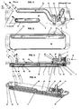
Fig. 1 Draufsicht auf einen Plattenwärmeübertrager; -
Fig. 2 eine Ansicht von unten auf den Plattenwärmeübertrager derFig. 1 ; - Die
Fig. 3 und 4 zeigen ähnliche Schnitte durch den Plattenwärmeübertrager, die durch die Kanäle auf der Flüssigkeitsseite verlaufen. - Die
Fig. 5 zeigt eine Draufsicht auf einen Plattenwärmeübertrager gemäß dem alternativen Lösungsvorschlag. - Die
Fig. 6 zeigt eine Alternative zurFig. 2 - Der abgebildete Plattenwärmeübertrager ist ein Getriebeölkühler, der beispielsweise in einem Kraftfahrzeug eingesetzt werden kann, um das Getriebeöl mittels der Kühlflüssigkeit des Fahrzeugmotors zu temperieren. Zur Temperierung dient ein Thermostat - Regelventil 25 in einem Gehäuse 22, das auf der einen Platte, im Ausführungsbeispiel auf der Deckplatte 20, des Plattenwärmeübertragers angeordnet und mit Befestigungsmitteln 63 mit der Deckplatte 20 verbunden ist. Wie aus den
Fig. 3 und 4 hervorgeht, besitzt das Gehäuse 22 eine Kammer 28 und eine Abteilung 29. Die Kammer 28 ist von der Abteilung 29 hydraulisch getrennt. In die Kammer 28 ragt der Thermostat 23 hinein, während sich in der Abteilung 29 an sich bekannte Elemente des Regelventils, wie Ventilstange, Ventilteller usw. erstrecken. Die hydraulische Trennung kann mittels Dichtungen am Thermostat 23 vorgenommen werden. Am die Abteilung 29 bildenden Gehäuse 22 ist ein Anschluss 27 für gekühlte Kühlflüssigkeit KW und ein anderer Anschluss 26 für vorgewärmte Kühlflüssigkeit WW angeordnet. Je nach vorliegender Temperatur des Öls wird der Thermostat 23 die Ventilstange mit dem Ventilteller so bewegen, dass entweder nur gekühlte Kühlflüssigkeit KW, nur angewärmte Kühlflüssigkeit WW oder eine Mischung aus KW und WW aus der Abteilung 29 in den Eintrittskanal 5 für die Kühlflüssigkeit des Plattenwärmeübertragers einströmen wird, um somit das Getriebeöl möglichst im Bereich des Temperaturoptimums zu halten bzw. zu bringen. In der Deckplatte 20 ist ein Überführungskanal 21 ausgebildet, durch den das Öl von seinem Austrittskanal 8 zu seiner vorgesehenen Austrittsstelle Öl (aus) strömt. Der Eintrittskanal 7 für das Öl wurde lediglich am Stutzen Öl (ein) angedeutet. Das Öl durchströmt die Strömungskanäle 1 im Plattenwärmeübertrager vom Eintrittskanal 7 zum Austrittskanal 8. In dem erwähnten Überführungskanal 21 für das Öl befindet sich ein Ausschnitt 50 mit einem Strömungslenkelement 51, um das Öl in die Kammer 28 und an den Thermostaten 23 zu leiten, was in derFig. 3 durch einen gestrichelten Pfeil angezeigt ist. Im Übrigen zeigen die anderen gestrichelten Pfeile die Strömung des Öls und die durchgezogenen Pfeile die Strömung der Kühlflüssigkeit an, auf die im Folgenden noch näher eingegangen werden soll. Wie bereits beschrieben, strömt die Kühlflüssigkeit in den Eintrittskanal 5 ein. Sie verteilt sich dort in einen Teilstrom T1, der dort in die Strömungskanäle 2 für die Kühlflüssigkeit eintritt. In derFig. 3 wurde lediglich ein einziger Pfeil T1 eingezeichnet. Der andere Teilstrom T2 strömt durch den in der anderen Platte, im Ausführungsbeispiel in der Grundplatte 10, ausgebildeten Überleitungskanal 11 zum diametralen Ende des Plattenwärmeübertragers. Dort ist ein zweiter Eintrittskanal 5.1 ausgebildet, über den der Teilstrom T2 Zugang zu den Strömungskanälen 2 hat, um in konkurrierender Strömungsrichtung mit dem Teilstrom T1 zum Austrittskanal 6 zu gelangen. Der Austrittskanal 6 ist etwa in der Mitte des Plattenwärmeübertragers angeordnet. Vom Austrittskanal 6 strömt die Kühlflüssigkeit in einen auf der Deckplatte 20 angeordneten zweiten Überleitungskanal 30, der zum Austrittsstutzen 40 für Kühlflüssigkeit W(aus) führt. Der Austrittsstutzen 40 und der Austrittskanal 6 besitzen einen Abstand voneinander. Es versteht sich, dass bei einer möglichen Umkehr der Durchströmung die Teilströme T1 und T2 divergierende Strömungsrichtung besitzen. - Es ist durch die Erfindung möglich geworden, die Ein - und Austritte für beide Medien zu frei wählbaren Stellen im Bereich der Grund - bzw. der Deckplatte 20 zu leiten. Dies erfolgt durch entsprechende Ausbildung der Überführungs - und der Überleitungskanäle 11, 21, 30, die jede beliebige Form aufweisen können. Daraus ist ersichtlich, dass durch die Erfindung die Anschlussmöglichkeiten des Plattenwärmeübertragers in sehr beengten Einbauräumen wesentlich verbessert wurden.
- Die Aufteilung des Kühlflüssigkeitsstroms in die Teilströme T1 und T2 kann durch bekannte konstruktive Maßnahmen, wie beispielsweise die Dimensionierung der Strömungskanäle 2 und der Überleitungskanäle 11 und 30 oder auch durch entsprechende Wahl der Kanallängen in die gewünschte Richtung beeinflusst werden. Mit besonderem Vorteil ist die Erfindung bei Plattenwärmeübertragern einsetzbar, die eine relativ geringe Anzahl von Strömungskanälen 1, 2 bei ziemlich großer Länge derselben aufweisen, um den Druckverlust zu reduzieren.
- Wie die beiliegenden Figuren ferner zeigen, besitzt die Deckplatte 20 des Plattenwärmeübertragers einen Überstand 60, der über den aus Wärmeübertragerplatten 3 gebildeten Stapel hinausragt. Dieser Überstand 60 wird genutzt, um insbesondere eine schwingungsdämpfende Befestigung 61, 62 des Plattenwärmeübertragers vornehmen zu können.
- Im alternativen Lösungsvorschlag, der in der
Fig. 5 gezeigt ist, wurden lediglich aus ökonomischen Gründen relativ wenig Änderungen gegenüber dem ersten Lösungsvorschlag vorgenommen. Es wurden für gleiche Teile die gleichen Bezugszeichen verwendet. Die Positionen für Öl(ein) und Öl (aus) wurden nicht verändert. Die Überleitungskanäle 30, 11 und der Überführungskanal 21 wurden lediglich als gerade Kanäle ausgebildet, obwohl jeder beliebige andere, insbesondere auch kurvenförmige Verlauf vorgenommen werden könnte. Sie befinden sich an der einen Platte, im Ausführungsbeispiel an der Deckplatte 20. Auch in diesem Lösungsvorschlag wurde ein Thermostat-Regelventil 25 eingesetzt. Es befindet sich ebenfalls auf der Deckplatte 20, könnte aber auch an anderen Stellen angeordnet sein. Im Übrigen ist erkennbar, dass es sich um körperlich das gleiche Regelventil 25 handelt, wie im ersten Vorschlag. Es könnte entsprechend angepasst werden. Die Ein - bzw. Austrittskanäle 5, 5.1, 7 und 8 wurden angedeutet. Der Austrittskanal 6 für die Kühlflüssigkeit wird vom Thermostat-Regelventil 25 verdeckt. Insgesamt ist aus der Darstellung mit den gestrichelten Strömungspfeilen für das Öl und den durchgezogen Strömungspfeilen für die Kühlflüssigkeit erkennbar, dass dieser Alternatiworschlag die erwähnten zusätzlichen Vorteile bietet. Hinsichtlich der Durchströmung des Plattenwärmeübertragers auf der Kühlflüssigkeitsseite unterscheidet sich der Alternatiworschlag von dem ersten Vorschlag dadurch, dass der gesamte Kühlflüssigkeitsstrom zunächst in den Überleitungskanal 11 eintritt und sich auf die beiden diametralen Enden des Plattenwärmeübertragers verteilt, um dort in die Eintrittskanäle 5, 5.1 einzutreten. Im ersten Lösungsvorschlag bilden sich demgegenüber, wie vorstehend beschrieben, die Teilströme T1 und T2 im Eintrittskanal 5 aus. - In der
Fig. 6 ist ein Überleitungskanal 11 zu erkennen, der Abbiegungen 70 aufweist, die allerdings auch in derFig. 1 , am Überführungskanal 21, zu sehen sind. Der Einfachheit halber wurden die Positionen der Kanäle 5, 5.1 nicht verändert, was jedoch durch die Möglichkeit, beliebig geformte Überführungs - bzw. Überleitungskanäle vorzusehen, leicht realisierbar wäre.
Claims (9)
- Plattenwärmeübertrager, beispielsweise ein Getriebeölkühler, in dem das Getriebeöl mit einer Flüssigkeit im Wärmeaustausch ist, wobei der Plattenwärmeübertrager aus ineinander gestapelten und getrennte Strömungskanäle (1, 2) bildenden Wärmeübertragerplatten (3) besteht, die jeweils Öffnungen (4) aufweisen, die im Stapel der Wärmeübertragerplatten (3) Kanäle (5, 6, 7, 8) bilden, die der Zu - bzw. der Abführung der Medien dienen, sowie mit wenigstens einer oberen Platte (20) und wenigstens einer unteren Platte (10), und mit einem Überführungskanal (21), der an der oberen Platte (20) oder an der unteren Platte (10) ausgebildet ist, um ein Medium zu einer gewünschten Position der Zu - oder der Abführung zu leiten,
wobei der Überführungskanal (21) an der einen Platte (10 oder 20) für das eine Medium vorgesehen ist, und wobei an der einen oder an der anderen Platte (10 oder 20) ein Überleitungskanal (11) ausgebildet ist, der zur Überleitung des anderen Mediums dient,dadurch gekennzeichnet, dass am Überführungskanal (21) der einen Platte (10 oder 20) ein Thermostat - Regelventil (25) in einem Gehäuse (22) angeordnet ist, dessen Thermostat (23) mit dem einen Medium, vorzugsweise Öl, über einen Ausschnitt (50) im Überführungskanal (21) in Kontakt kommt. - Plattenwärmeübertrager nach Anspruch 1, dadurch gekennzeichnet, dass der Überleitungskanal (11) an der anderen Platte (10 oder 20) vorzugsweise für die Flüssigkeit gedacht ist und der Überführungskanal (21) in der einen Platte (10 oder 20) für das Öl vorgesehen ist.
- Plattenwärmeübertrager nach Anspruch 1, dadurch gekennzeichnet, dass an der einen Platte (10 oder 20) ein zweiter Überleitungskanal (30), vorzugsweise für die Flüssigkeit ausgebildet ist.
- Plattenwärmeübertrager nach Anspruch 1, dadurch gekennzeichnet, dass die im Plattenwärmeübertrager vorhandenen Strömungskanäle (1) für das eine Medium (vorzugsweise Öl) in einer Richtung über etwa die Gesamtlänge des Plattenwärmeübertragers durchströmbar sind, während die davon getrennten Strömungskanäle (2) für das andere Medium (vorzugsweise Kühlflüssigkeit) gegensinnig durchströmbar sind, wobei das andere Medium in seinem Eintrittskanal (5) in zwei Teilströme (T1, T2) aufgeteilt ist, wobei der eine Teilstrom (T1) am Eintrittskanal (5) in seine Strömungskanäle (2) eintritt und der andere Teilstrom (T2) über den Überleitungskanal (11) zum gegenüberliegenden Ende des Plattenwärmeübertragers strömt, um dort in die ihm zugeordneten Strömungskanäle (2) einzutreten, so dass beide Teilströme (T1, T2) des anderen Mediums im Plattenwärmeübertrager konkurrierende Strömungsrichtung besitzen, wobei bei Umkehr der Durchströmung die Teilströme (T1, T2) divergierende Strömungsrichtung besitzen.
- Plattenwärmeübertrager nach Anspruch 1 und 4, dadurch gekennzeichnet, dass die konkurrierenden oder divergierenden Teilströme (T1, T2) sich etwa in der Mitte des Plattenwärmeübertragers treffen oder in divergierender Richtung strömen, wozu sie einen gemeinsamen Austritts - bzw. Eintrittskanal (6) besitzen.
- Plattenwärmeübertrager nach Anspruch 1, 3, 4 oder 5, dadurch gekennzeichnet, dass der Austrittskanal (6) in dem zweiten Überleitungskanal (30) mündet, der zu einem im Abstand vom Austrittskanal (6) angeordneten Auslassstutzen (40) führt.
- Plattenwärmeübertrager nach Anspruch 1 und 2, dadurch gekennzeichnet, dass das Gehäuse (22) des Thermostat-Regelventils (25) einen Anschluss (26) für kühlere Flüssigkeit und einen anderen Anschluss (27) für wärmere Flüssigkeit aufweist, und dass je nach Temperatur des Öls eine Flüssigkeitstemperatur einstellbar ist, die dazu beiträgt, dass das Öl im Bereich seines Temperaturoptimums temperierbar ist.
- Plattenwärmeübertrager nach Anspruch 1, 2 und 7, dadurch gekennzeichnet, dass das Gehäuse (22) des Thermostat - Regelventils (25) eine Kammer (28) für das Öl aufweist, in der das Öl mit dem Thermostat (23) in Kontakt ist und eine Abteilung (29) für die Flüssigkeit, die mit einem Zuführkanal des Plattenwärmeübertragers hydraulisch verbunden ist und in der die Anschlüsse (26, 27) für die unterschiedliche Temperatur aufweisenden Flüssigkeitsströme münden.
- Plattenwärmeübertrager nach Anspruch 1, 2, 7 und 8, dadurch gekennzeichnet, dass im Ausschnitt (50) ein Strömungslenkelement (51) angeordnet ist, um das Öl in die Kammer (28) zu leiten.
Applications Claiming Priority (2)
| Application Number | Priority Date | Filing Date | Title |
|---|---|---|---|
| DE102004004975 | 2004-01-31 | ||
| DE200410004975 DE102004004975B4 (de) | 2004-01-31 | 2004-01-31 | Plattenwärmeübertrager |
Publications (3)
| Publication Number | Publication Date |
|---|---|
| EP1559980A1 EP1559980A1 (de) | 2005-08-03 |
| EP1559980B1 true EP1559980B1 (de) | 2012-05-23 |
| EP1559980B2 EP1559980B2 (de) | 2022-05-18 |
Family
ID=34638826
Family Applications (1)
| Application Number | Title | Priority Date | Filing Date |
|---|---|---|---|
| EP05000457.1A Ceased EP1559980B2 (de) | 2004-01-31 | 2005-01-12 | Plattenwärmeübertrager |
Country Status (3)
| Country | Link |
|---|---|
| US (1) | US7748442B2 (de) |
| EP (1) | EP1559980B2 (de) |
| DE (1) | DE102004004975B4 (de) |
Cited By (2)
| Publication number | Priority date | Publication date | Assignee | Title |
|---|---|---|---|---|
| DE102015221528A1 (de) | 2015-11-03 | 2017-05-04 | Mahle International Gmbh | Wärmeübertragermodul |
| EP4297251A1 (de) * | 2022-06-21 | 2023-12-27 | Valeo eAutomotive Germany GmbH | Elektrische antriebseinheit mit verbessertem kühlkonzept |
Families Citing this family (34)
| Publication number | Priority date | Publication date | Assignee | Title |
|---|---|---|---|---|
| EP1500896A3 (de) * | 2003-07-23 | 2009-12-16 | Invensys APV A/S | Koppelelement für Wärmetauscher |
| US8127137B2 (en) | 2004-03-18 | 2012-02-28 | Digimarc Corporation | Watermark payload encryption for media including multiple watermarks |
| GB0411870D0 (en) * | 2004-05-27 | 2004-06-30 | Hansen Transmissions Int | Water cooling device |
| DE102005048294A1 (de) * | 2005-10-08 | 2007-04-12 | Modine Manufacturing Co., Racine | Gelöteter Wärmetauscher und Herstellungsverfahren |
| US7753105B2 (en) * | 2006-05-16 | 2010-07-13 | Delphi Technologies, Inc. | Liquid cooled condenser having an integrated heat exchanger |
| DE102006030790A1 (de) | 2006-06-30 | 2008-01-03 | Zf Friedrichshafen Ag | Wärmetauscher mit integriertem Bypass-Ventil |
| DE102008031684B4 (de) * | 2008-07-04 | 2020-02-06 | Mahle International Gmbh | Kühleinrichtung |
| EP2251631A1 (de) * | 2009-05-11 | 2010-11-17 | SPX APV Danmark A/S | Heizvorrichtung und Verfahren zu deren Herstellung |
| JP5694712B2 (ja) * | 2010-09-10 | 2015-04-01 | 株式会社マーレ フィルターシステムズ | オイルクーラ |
| FR2967248B1 (fr) * | 2010-11-10 | 2015-01-23 | Valeo Systemes Thermiques | Echangeur de chaleur fluide/fluide |
| US9239195B2 (en) * | 2011-04-26 | 2016-01-19 | Hyundai Motor Company | Heat exchanger for vehicle |
| KR101283591B1 (ko) * | 2011-09-19 | 2013-07-05 | 현대자동차주식회사 | 차량용 열교환기 |
| DE112013002728T5 (de) | 2012-05-31 | 2015-03-19 | Dana Canada Corporation | Wärmetauscheranordnungen mit integriertem Ventil |
| US10087793B2 (en) | 2015-01-26 | 2018-10-02 | Modine Manufacturing Company | Thermal management unit for vehicle powertrain |
| US10619530B2 (en) | 2015-01-26 | 2020-04-14 | Modine Manufacturing Company | Thermal management unit for vehicle powertrain |
| US9920829B2 (en) * | 2015-03-10 | 2018-03-20 | Zf Friedrichshafen Ag | Cooler for a marine transmission gearbox |
| DE102015207593A1 (de) | 2015-04-24 | 2016-10-27 | Mahle International Gmbh | Ölkühler |
| JP2017015278A (ja) * | 2015-06-29 | 2017-01-19 | カルソニックカンセイ株式会社 | 熱交換器 |
| JP6086132B2 (ja) * | 2015-07-28 | 2017-03-01 | トヨタ自動車株式会社 | 車両用熱交換器 |
| CN106481436B (zh) * | 2015-08-25 | 2020-05-15 | 康明斯公司 | 用于发动机的滤头的冷却组件 |
| DE102015216481A1 (de) * | 2015-08-28 | 2017-03-02 | Volkswagen Aktiengesellschaft | Wärmetauscher in Plattenbauweise mit Bypass sowie Verfahren zur Herstellung eines Wärmetauschers in Plattenbauweise mit Bypass |
| JP6390574B2 (ja) * | 2015-09-29 | 2018-09-19 | マツダ株式会社 | 変速機及びその製造方法 |
| WO2018035614A1 (en) | 2016-08-26 | 2018-03-01 | Dana Canada Corporation | Locating mechanism for heat exchanger assembly |
| US11285781B2 (en) * | 2016-11-09 | 2022-03-29 | Zhejiang Sanhua Intelligent Controls Co., Ltd | Fluid heat exchange assembly, and heat management system of vehicle |
| US10520075B2 (en) * | 2017-05-31 | 2019-12-31 | Mahle International Gmbh | Apparatus for controlling the temperature of an oil cooler in a motor vehicle |
| DE102018102542A1 (de) * | 2018-01-29 | 2019-08-01 | Woco Industrietechnik Gmbh | Vorrichtung zur Handhabung von Fluiden sowie Verfahren zur Herstellung derselben |
| US10900557B2 (en) | 2018-11-13 | 2021-01-26 | Dana Canada Corporation | Heat exchanger assembly with integrated valve with pressure relief feature for hot and cold fluids |
| JP7171453B2 (ja) * | 2019-01-18 | 2022-11-15 | 株式会社ティラド | サーモバルブ一体型のオイルクーラまたはオイルウォーマ |
| US11274884B2 (en) * | 2019-03-29 | 2022-03-15 | Dana Canada Corporation | Heat exchanger module with an adapter module for direct mounting to a vehicle component |
| DE102020204271A1 (de) * | 2019-04-05 | 2020-10-08 | Dana Canada Corporation | Wärmetauscheranordnung mit integriertem Ventil und Druckbypass |
| US11747095B2 (en) * | 2019-07-31 | 2023-09-05 | Denso International America, Inc. | Heat exchanger with hybrid counter cross flow |
| DE102022202732A1 (de) | 2022-03-21 | 2023-09-21 | Mahle International Gmbh | Stapelscheiben-Wärmeübertrager für ein Thermomanagementmodul |
| FR3134883A1 (fr) * | 2022-04-22 | 2023-10-27 | Valeo Systemes Thermiques | Support pour module de gestion des fluides pour un véhicule notamment automobile et module de gestion des fluides comportant un tel support |
| US12550290B2 (en) | 2023-10-12 | 2026-02-10 | Quanta Computer Inc. | Cold plate with streamlined coolant tubes |
Family Cites Families (33)
| Publication number | Priority date | Publication date | Assignee | Title |
|---|---|---|---|---|
| US1992097A (en) * | 1933-04-04 | 1935-02-19 | Seligman Richard | Surface heat exchange apparatus for fluids |
| US4303124A (en) * | 1979-06-04 | 1981-12-01 | The A.P.V. Company Limited | Plate heat exchanger |
| US4503908A (en) * | 1979-10-01 | 1985-03-12 | Rockwell International Corporation | Internally manifolded unibody plate for a plate/fin-type heat exchanger |
| JPS6113178U (ja) * | 1984-06-28 | 1986-01-25 | 株式会社 土屋製作所 | ハウジングレス熱交換器 |
| US4708199A (en) * | 1985-02-28 | 1987-11-24 | Kabushiki Kaisha Tsuchiya Seisakusho | Heat exchanger |
| JPH073315B2 (ja) * | 1985-06-25 | 1995-01-18 | 日本電装株式会社 | 熱交換器 |
| JP2737987B2 (ja) * | 1989-03-09 | 1998-04-08 | アイシン精機株式会社 | 積層型蒸発器 |
| DE3938253A1 (de) * | 1989-11-17 | 1991-05-23 | Behr Gmbh & Co | Oelkuehler fuer eine brennkraftmaschine |
| FR2656412B1 (fr) * | 1989-12-21 | 1995-02-17 | Valeo Thermique Moteur Sa | Echangeur de chaleur a lames, en particulier pour le refroidissement de l'huile de lubrification d'un vehicule automobile. |
| JP2521328Y2 (ja) * | 1990-08-06 | 1996-12-25 | カルソニック株式会社 | 自動変速機用オイルクーラ |
| US5078209A (en) * | 1991-02-06 | 1992-01-07 | Modine Manufacturing Co. | Heat exchanger assembly |
| JP2558019Y2 (ja) * | 1992-09-24 | 1997-12-17 | カルソニック株式会社 | オイルクーラ |
| US5464056A (en) * | 1992-12-21 | 1995-11-07 | Calsonic Corporation | Housingless type oil cooler and method for producing the same |
| IT1271978B (it) * | 1993-03-05 | 1997-06-10 | Giannoni Srl | Gruppo scambiatore a piastre dispositivo di controllo e relativo scambiatore. |
| DE9309741U1 (de) * | 1993-06-30 | 1993-08-26 | Filterwerk Mann & Hummel Gmbh, 71638 Ludwigsburg | Wärmetauscher |
| JP3663981B2 (ja) * | 1999-06-30 | 2005-06-22 | 株式会社デンソー | 熱交換器及びそのろう付け方法 |
| DE19519740B4 (de) * | 1995-06-02 | 2005-04-21 | Mann + Hummel Gmbh | Wärmetauscher |
| SE9502189D0 (sv) * | 1995-06-16 | 1995-06-16 | Tetra Laval Holdings & Finance | Plattvärmeväxlare |
| DE59703327D1 (de) † | 1996-02-01 | 2001-05-17 | Modine Mfg Co | Vorrichtung zur Temperierung des Getriebeöls eines Kraftfahrzeuges |
| DE19628561C1 (de) * | 1996-07-16 | 1997-09-04 | Laengerer & Reich Gmbh & Co | Plattenwärmetauscher |
| DE19637817A1 (de) * | 1996-09-17 | 1998-03-19 | Laengerer & Reich Gmbh & Co | Einrichtung und Verfahren zum Kühlen und Vorwärmen |
| DE19654362B4 (de) * | 1996-12-24 | 2007-12-06 | Behr Gmbh & Co. Kg | Wärmeübertrageranordnung |
| DE19654365B4 (de) * | 1996-12-24 | 2007-09-27 | Behr Gmbh & Co. Kg | Plattenwärmeübertrager |
| DE19707647B4 (de) * | 1997-02-26 | 2007-03-01 | Behr Gmbh & Co. Kg | Scheibenkühler |
| DE19709601C5 (de) * | 1997-03-08 | 2007-02-01 | Behr Industry Gmbh & Co. Kg | Plattenwärmeübertrager |
| DE19750814C5 (de) * | 1997-11-17 | 2005-08-18 | Modine Manufacturing Co., Racine | Wärmetauscher, insbesondere Ölkühler |
| CA2260890A1 (en) * | 1999-02-05 | 2000-08-05 | Long Manufacturing Ltd. | Self-enclosing heat exchangers |
| FR2790073B1 (fr) * | 1999-02-24 | 2001-06-08 | Mer Joseph Marie Le | Echangeur thermique a plaques, a vanne integree |
| CA2272804C (en) * | 1999-05-28 | 2004-07-20 | Long Manufacturing Ltd. | Heat exchanger with dimpled bypass channel |
| DE10019029C5 (de) * | 2000-04-18 | 2017-11-23 | Mahle International Gmbh | Vorrichtung zum Kühlen und/oder Temperieren von Öl |
| CA2383649C (en) * | 2002-04-24 | 2009-08-18 | Long Manufacturing Ltd. | Inverted lid sealing plate for heat exchanger |
| DE10328638A1 (de) * | 2003-06-26 | 2005-01-20 | Modine Manufacturing Co., Racine | Wärmetauscher in gehäuseloser Plattenbauweise |
| US7377308B2 (en) * | 2006-05-09 | 2008-05-27 | Modine Manufacturing Company | Dual two pass stacked plate heat exchanger |
-
2004
- 2004-01-31 DE DE200410004975 patent/DE102004004975B4/de not_active Expired - Lifetime
-
2005
- 2005-01-12 EP EP05000457.1A patent/EP1559980B2/de not_active Ceased
- 2005-01-28 US US11/046,512 patent/US7748442B2/en active Active
Cited By (2)
| Publication number | Priority date | Publication date | Assignee | Title |
|---|---|---|---|---|
| DE102015221528A1 (de) | 2015-11-03 | 2017-05-04 | Mahle International Gmbh | Wärmeübertragermodul |
| EP4297251A1 (de) * | 2022-06-21 | 2023-12-27 | Valeo eAutomotive Germany GmbH | Elektrische antriebseinheit mit verbessertem kühlkonzept |
Also Published As
| Publication number | Publication date |
|---|---|
| EP1559980A1 (de) | 2005-08-03 |
| US7748442B2 (en) | 2010-07-06 |
| DE102004004975B4 (de) | 2015-04-23 |
| DE102004004975A1 (de) | 2005-08-18 |
| US20050205236A1 (en) | 2005-09-22 |
| EP1559980B2 (de) | 2022-05-18 |
Similar Documents
| Publication | Publication Date | Title |
|---|---|---|
| EP1559980B1 (de) | Plattenwärmeübertrager | |
| EP1152204B1 (de) | Plattenwärmetauscher | |
| EP2205922B1 (de) | Wärmetauscher, insbesondere ölkühler | |
| DE112017002349B4 (de) | Wärmetauscher | |
| EP3119623B1 (de) | Heizkühlmodul | |
| DE19750814C5 (de) | Wärmetauscher, insbesondere Ölkühler | |
| EP1306638B1 (de) | Gehäuseloser Plattenwärmetauscher | |
| DE19709601C5 (de) | Plattenwärmeübertrager | |
| DE102020204271A1 (de) | Wärmetauscheranordnung mit integriertem Ventil und Druckbypass | |
| DE102013220031A1 (de) | Wärmeübertrager | |
| WO2004005832A1 (de) | Vorrichtung zum wärmeaustausch zwischen strömungsfähigen medien | |
| DE112011104558T5 (de) | Fluidströmungsmischbox mit Fluidströmungsregeleinrichtung | |
| DE10102640A1 (de) | Wärmetauscher | |
| EP0200809A2 (de) | Ölfilter mit integriertem Wärmetauscher | |
| DE102007054703B4 (de) | Wärmetauscher | |
| DE102017219433A1 (de) | Wärmeübertrager für einen Verbrennungsmotor | |
| DE69924647T2 (de) | Plattenwärmetauscher mit integriertem ventil | |
| EP1870655A2 (de) | Wärmeübertragungseinheit für eine Verbrennungskraftmaschine | |
| DE10049890B4 (de) | Stapelscheiben-Wärmeübertrager | |
| EP1687579B1 (de) | Ladeluft-/kühlmittel-kühler | |
| DE4437877C2 (de) | Wärmetauscher, insbesondere Ölkühler | |
| DE102006061440A1 (de) | Kühlflüssigkeitskühler | |
| DE102004020602A1 (de) | Plattenwärmetauscher mit Strömungswegen für drei Wärmetauschfluide | |
| EP0197169B1 (de) | Ölkühler | |
| DE102007027250A1 (de) | Wärmeübertragereinrichtung |
Legal Events
| Date | Code | Title | Description |
|---|---|---|---|
| PUAI | Public reference made under article 153(3) epc to a published international application that has entered the european phase |
Free format text: ORIGINAL CODE: 0009012 |
|
| AK | Designated contracting states |
Kind code of ref document: A1 Designated state(s): AT BE BG CH CY CZ DE DK EE ES FI FR GB GR HU IE IS IT LI LT LU MC NL PL PT RO SE SI SK TR |
|
| AX | Request for extension of the european patent |
Extension state: AL BA HR LV MK YU |
|
| 17P | Request for examination filed |
Effective date: 20060203 |
|
| AKX | Designation fees paid |
Designated state(s): DE ES FR GB IT SE |
|
| 17Q | First examination report despatched |
Effective date: 20070605 |
|
| GRAP | Despatch of communication of intention to grant a patent |
Free format text: ORIGINAL CODE: EPIDOSNIGR1 |
|
| RBV | Designated contracting states (corrected) |
Designated state(s): DE FR GB |
|
| GRAS | Grant fee paid |
Free format text: ORIGINAL CODE: EPIDOSNIGR3 |
|
| GRAA | (expected) grant |
Free format text: ORIGINAL CODE: 0009210 |
|
| AK | Designated contracting states |
Kind code of ref document: B1 Designated state(s): DE FR GB |
|
| REG | Reference to a national code |
Ref country code: GB Ref legal event code: FG4D Free format text: NOT ENGLISH |
|
| REG | Reference to a national code |
Ref country code: DE Ref legal event code: R096 Ref document number: 502005012735 Country of ref document: DE Effective date: 20120712 |
|
| PLBI | Opposition filed |
Free format text: ORIGINAL CODE: 0009260 |
|
| 26 | Opposition filed |
Opponent name: BEHR GMBH & CO. KG Effective date: 20130225 |
|
| PLAX | Notice of opposition and request to file observation + time limit sent |
Free format text: ORIGINAL CODE: EPIDOSNOBS2 |
|
| REG | Reference to a national code |
Ref country code: DE Ref legal event code: R026 Ref document number: 502005012735 Country of ref document: DE Effective date: 20130225 |
|
| PLAF | Information modified related to communication of a notice of opposition and request to file observations + time limit |
Free format text: ORIGINAL CODE: EPIDOSCOBS2 |
|
| PLBB | Reply of patent proprietor to notice(s) of opposition received |
Free format text: ORIGINAL CODE: EPIDOSNOBS3 |
|
| PLAB | Opposition data, opponent's data or that of the opponent's representative modified |
Free format text: ORIGINAL CODE: 0009299OPPO |
|
| R26 | Opposition filed (corrected) |
Opponent name: MAHLE BEHR GMBH & CO. KG Effective date: 20130225 |
|
| REG | Reference to a national code |
Ref country code: FR Ref legal event code: PLFP Year of fee payment: 12 |
|
| PLCK | Communication despatched that opposition was rejected |
Free format text: ORIGINAL CODE: EPIDOSNREJ1 |
|
| APAH | Appeal reference modified |
Free format text: ORIGINAL CODE: EPIDOSCREFNO |
|
| APBM | Appeal reference recorded |
Free format text: ORIGINAL CODE: EPIDOSNREFNO |
|
| APBP | Date of receipt of notice of appeal recorded |
Free format text: ORIGINAL CODE: EPIDOSNNOA2O |
|
| APBQ | Date of receipt of statement of grounds of appeal recorded |
Free format text: ORIGINAL CODE: EPIDOSNNOA3O |
|
| REG | Reference to a national code |
Ref country code: FR Ref legal event code: PLFP Year of fee payment: 13 |
|
| REG | Reference to a national code |
Ref country code: FR Ref legal event code: PLFP Year of fee payment: 14 |
|
| PLAO | Information deleted related to despatch of communication that opposition is rejected |
Free format text: ORIGINAL CODE: EPIDOSDREJ1 |
|
| STAA | Information on the status of an ep patent application or granted ep patent |
Free format text: STATUS: THE PATENT HAS BEEN GRANTED |
|
| PLAY | Examination report in opposition despatched + time limit |
Free format text: ORIGINAL CODE: EPIDOSNORE2 |
|
| APAW | Appeal reference deleted |
Free format text: ORIGINAL CODE: EPIDOSDREFNO |
|
| APAY | Date of receipt of notice of appeal deleted |
Free format text: ORIGINAL CODE: EPIDOSDNOA2O |
|
| APBA | Date of receipt of statement of grounds of appeal deleted |
Free format text: ORIGINAL CODE: EPIDOSDNOA3O |
|
| APBM | Appeal reference recorded |
Free format text: ORIGINAL CODE: EPIDOSNREFNO |
|
| APBP | Date of receipt of notice of appeal recorded |
Free format text: ORIGINAL CODE: EPIDOSNNOA2O |
|
| APBQ | Date of receipt of statement of grounds of appeal recorded |
Free format text: ORIGINAL CODE: EPIDOSNNOA3O |
|
| PLAP | Information related to despatch of examination report in opposition + time limit deleted |
Free format text: ORIGINAL CODE: EPIDOSDORE2 |
|
| APBU | Appeal procedure closed |
Free format text: ORIGINAL CODE: EPIDOSNNOA9O |
|
| PUAH | Patent maintained in amended form |
Free format text: ORIGINAL CODE: 0009272 |
|
| STAA | Information on the status of an ep patent application or granted ep patent |
Free format text: STATUS: PATENT MAINTAINED AS AMENDED |
|
| PGFP | Annual fee paid to national office [announced via postgrant information from national office to epo] |
Ref country code: GB Payment date: 20220127 Year of fee payment: 18 Ref country code: DE Payment date: 20220127 Year of fee payment: 18 |
|
| 27A | Patent maintained in amended form |
Effective date: 20220518 |
|
| AK | Designated contracting states |
Kind code of ref document: B2 Designated state(s): DE FR GB |
|
| REG | Reference to a national code |
Ref country code: DE Ref legal event code: R102 Ref document number: 502005012735 Country of ref document: DE |
|
| PGFP | Annual fee paid to national office [announced via postgrant information from national office to epo] |
Ref country code: FR Payment date: 20220125 Year of fee payment: 18 |
|
| REG | Reference to a national code |
Ref country code: DE Ref legal event code: R119 Ref document number: 502005012735 Country of ref document: DE |
|
| GBPC | Gb: european patent ceased through non-payment of renewal fee |
Effective date: 20230112 |
|
| PG25 | Lapsed in a contracting state [announced via postgrant information from national office to epo] |
Ref country code: GB Free format text: LAPSE BECAUSE OF NON-PAYMENT OF DUE FEES Effective date: 20230112 Ref country code: DE Free format text: LAPSE BECAUSE OF NON-PAYMENT OF DUE FEES Effective date: 20230801 |
|
| PG25 | Lapsed in a contracting state [announced via postgrant information from national office to epo] |
Ref country code: FR Free format text: LAPSE BECAUSE OF NON-PAYMENT OF DUE FEES Effective date: 20230131 |