EP1559989A1 - Stufen- und Abstandsmessvorrichtung - Google Patents
Stufen- und Abstandsmessvorrichtung Download PDFInfo
- Publication number
- EP1559989A1 EP1559989A1 EP05001675A EP05001675A EP1559989A1 EP 1559989 A1 EP1559989 A1 EP 1559989A1 EP 05001675 A EP05001675 A EP 05001675A EP 05001675 A EP05001675 A EP 05001675A EP 1559989 A1 EP1559989 A1 EP 1559989A1
- Authority
- EP
- European Patent Office
- Prior art keywords
- gap
- spindle
- contour line
- measurement
- contact point
- Prior art date
- Legal status (The legal status is an assumption and is not a legal conclusion. Google has not performed a legal analysis and makes no representation as to the accuracy of the status listed.)
- Granted
Links
- 238000005259 measurement Methods 0.000 claims description 68
- 238000006073 displacement reaction Methods 0.000 claims description 43
- 238000005520 cutting process Methods 0.000 description 8
- 239000011347 resin Substances 0.000 description 6
- 229920005989 resin Polymers 0.000 description 6
- 238000000034 method Methods 0.000 description 5
- 230000001154 acute effect Effects 0.000 description 2
- 239000000470 constituent Substances 0.000 description 2
- 238000010586 diagram Methods 0.000 description 2
- 230000000694 effects Effects 0.000 description 2
- 238000003780 insertion Methods 0.000 description 2
- 230000037431 insertion Effects 0.000 description 2
- 238000004519 manufacturing process Methods 0.000 description 2
- 239000000463 material Substances 0.000 description 2
- 230000002035 prolonged effect Effects 0.000 description 2
- 230000007423 decrease Effects 0.000 description 1
- 230000006866 deterioration Effects 0.000 description 1
- 238000012986 modification Methods 0.000 description 1
- 230000004048 modification Effects 0.000 description 1
- 230000000717 retained effect Effects 0.000 description 1
- 239000013585 weight reducing agent Substances 0.000 description 1
Images


Classifications
-
- G—PHYSICS
- G01—MEASURING; TESTING
- G01B—MEASURING LENGTH, THICKNESS OR SIMILAR LINEAR DIMENSIONS; MEASURING ANGLES; MEASURING AREAS; MEASURING IRREGULARITIES OF SURFACES OR CONTOURS
- G01B3/00—Measuring instruments characterised by the use of mechanical techniques
- G01B3/22—Feeler-pin gauges, e.g. dial gauges
Definitions
- the present invention relates to a step and gap measuring instrument, more specifically to a step and gap measuring instrument that is provided with a spindle disposed on a case body movably in the axial direction of the spindle and a contact point disposed at one end of the spindle, and measures the height of a step and/or the width of a gap by making the contact point abut a workpiece.
- a dial gage or the like has been used for the measurement of a step and a caliper or the like for the measurement of a gap.
- a dial gage or the like firstly to measure a step and a caliper or the like secondly to measure a gap, and that has involved an immense amount of time and effort.
- an inside measuring instrument is proposed in Japanese Unexamined Patent Publication No. Hei7-113603.
- the inside measuring instrument is configured so as to be equipped with: a case body; a spindle disposed on the case body movably in the axial direction thereof; a conical contact point that is disposed at the tip of the spindle and has a conical side face abutting a workpiece; a displacement detector that detects the displacement of the spindle; a computation controller that computes the gap between the measuring portions of the workpiece on the basis of the displacement of the spindle detected by the displacement detector and a constant based on the conical shape of the contact point and displays the computation results on a digital display; and a reference piece that is attached to the case body and provides a reference end face.
- Such an inside measuring instrument makes it possible to measure a gap of a workpiece by inserting a contact point into the gap. Firstly, the contact point is inserted into a gap until the reference end face of a reference piece abuts the reference flat face of a workpiece. By so doing, the spindle moves in such a direction that the spindle is squeezed in the case body and the displacement is detected by the displacement detector.
- the computation controller computes the gap of the workpiece on the basis of the detected displacement and a constant based on the conical shape of the contact point and displays the computation result on the digital display, and consequently an operator can know the gap by reading the result on the digital display.
- the inside measuring instrument can be also used as a conventional dial gage, it is possible to measure a step as well by using it.
- both a step and a gap can be measured with a single instrument.
- a gap cannot be measured in the case of a shape formed in such a way as integrating a step and a gap inseparably as shown in Fig. 12. That is, since the shape of the contact point of the inside measuring instrument is conical, it is impossible to insert the conical contact point perpendicularly to the gap in such a case as shown in Fig. 12, and consequently the gap cannot be measured.
- the main object of the present invention is to provide a step and gap measuring instrument capable of measuring a step and a gap even in the case of a shape formed by integrating the step and the gap inseparably.
- a step and gap measuring instrument the instrument is provided with: a case body; a spindle disposed on the case body movably in the axial direction thereof; a contact point being disposed at one end of the spindle and abutting a workpiece; a retainer that retains the case body in a predetermined posture; a displacement detector that detects the displacement of the spindle; and a display that displays the displacement detected by the displacement detector, wherein the contact point is provided with a step measuring portion and a gap measuring portion which abut the workpiece, the gap measuring portion is formed into a shape that contains one contour line and the other contour line that abut the workpiece at the time of gap measurement; the one contour line is formed in the direction parallel with the axial direction of the spindle; and the other contour line is formed so as to come closer to the one contour line along the axial direction of the spindle in the direction of going away from the spindle.
- a step can be measured by making the step measuring portion of the contact point abut the step portions of a workpiece sequentially and reading the difference of the measured values.
- a gap is measured by moving the spindle in the state of keeping the axis of the spindle perpendicular to the direction of the gap to be measured and inserting the contact point into the gap until the gap measuring portion abuts the two opposed faces that compose the gap.
- the distance of the insertion of the contact point into the gap is detected as the displacement of the spindle by the displacement detector and displayed by the display.
- the shape of the contact point is a given and an operator can obtain the width of the gap by computation and the like based on the displayed insertion amount and the given contact point shape.
- a gap can be measured even in the case of a shape formed by integrating a step and a gap inseparably.
- a gap is formed between two opposed faces, the one opposed face prolonged from a flat face on one side that is closer to the measuring instrument and the other opposed face prolonged from another flat face on the other side that is farther from the measuring instrument.
- a gap may be measured by inserting a contact point into the gap so as to make one contour line abut one opposed face and the other contour line abut the other opposed face. Since the one contour line is parallel with the axial direction of the spindle, it is possible to insert the contact point into the gap while the axis of the spindle is kept perpendicular to the direction of the gap and consequently the gap can be measured.
- the opposite contour line is a straight line that forms an angle of 45° with the first contour line; and the step measuring portion is formed on the intersection of the extension of the one contour line and the extension of the opposite contour line.
- the amount by which a step measuring portion intrudes into the gap coincides with the gap. Since the amount by which a step measuring portion intrudes into the gap is equal to the displacement of a spindle and is shown on a display, an operator can know the gap merely by reading the shown value. That is, at the time of gap measurement, it becomes unnecessary for an operator to calculate considering a shape of contact point to know the gap, and consequently time and effort of measurement can be reduced.
- the instrument is provided with: a computation controller that computes a gap of workpiece on the basis of a displacement of the spindle detected by a displacement detector and a shape of a contact point; and the display switching section that makes a display to show the displacement of the spindle detected by the displacement detector at the time of step measurement and the gap computed by the computation controller at the time of gap measurement.
- the present invention makes it possible to show on a display the gap computed by a computation controller using a display switching section, the gap can directly be read. As a consequence, it becomes unnecessary for an operator to compute considering the shape of a contact point to know the gap and time and effort of measurement can be reduced accordingly.
- At least either contour line out of the one contour line or the other contour line is formed on a curved face portion of a surface of the contact point.
- a measuring instrument When a measuring instrument is configured so that one or the other contour line is formed as an intersection line between flat face portions of the contact point surface and protrudes in the form of a comer on the contact point surface, at the time of gap measurement, the contact point abuts a workpiece at the comer on the contact point surface, and consequently the workpiece and the contact point are likely to be damaged.
- the contact point at the time of gap measurement, the contact point abuts the workpiece at the curved face portion of the contact point, and consequently not only the workpiece but also the contact point can be prevented from being damaged.
- measurement error is caused by a contact point that is configured so that one or the other contour line is formed on the flat face portion of the contact point surface. That is, since the flat face portion of the contact point surface cannot be inscribed in the inner wall of the circular hole, the one and the other contour line also cannot abut the inner wall and thus, the inner diameter measurement in such a state can not provide an accurate inner diameter.
- the gap measuring portion can abut the inner wall to be measured and thus such measurement error as mentioned above does not occur. That is, the present invention makes it possible to measure an inner portion without causing any measurement error regardless of the shapes of a gap, an inner diameter and the like.
- the contact point is provided with one columnar member and the other columnar member; one contour line is formed on the side surface of the one columnar member in the axial direction thereof; and the other contour line is formed on the side surface of the other columnar member in the axial direction thereof.
- the present invention only requires to attach columnar members that are easily produced as parts of the contact point. As a result, the present invention makes it possible to produce a contact point easily.
- the step measuring portion is a flat face perpendicular to the axial direction of the spindle.
- Fig. 1 shows a step and gap measuring instrument of the first embodiment according to the present invention.
- the step and gap measuring instrument is equipped with a dial gage 1, a base 2, made of resin, acting as a retainer that retains the dial gage in a predetermined posture, and a contact point 3 attached to the dial gage 1.
- the dial gage 1 is equipped with: a case body 11; a spindle 12 disposed on the case body 11 so as to be movable in the axial direction of the spindle 12; a displacement detector (not shown in the figure) to detect the displacement of the spindle 12; and a digital display 13 digitally displaying the displacement of the spindle 12 detected by the displacement detector.
- the case body 11 is equipped with: a case 111; a nearly cylindrical stem 112 disposed on the circumferential wall surface of the case 111; and a switch unit 113 disposed at the front face portion of the case.
- the switch unit 113 is composed of a power supply on/off switch 113A and a zero-set button 113B.
- the spindle 12 is attached to the case body 11 in the manner of being supported by the stem 112. At one end of the spindle 12 (the lower end thereof in Fig. 1), a tapped hole 121 with female thread is formed.
- the base 2 is attached to the stem 112.
- the base 2 has a measurement reference plane 21 perpendicular to the axial direction of the spindle 12 and, on the basis of it, the dial gage 1 can be retained in a predetermined posture, namely a posture wherein the spindle 12 is perpendicular to the measurement reference plane 21.
- the contact point 3 is provided with a contact block 31 and a thread portion 32.
- the thread portion 32 is formed by male thread cutting and the contact point 3 is attached to the spindle 12 by screwing the male thread to the tapped hole 121 of the spindle 12.
- Figs. 2 and 3 are the perspective view and the front view of the contact block 31 respectively.
- the contact block 31 is made of resin and provided with a gap measuring portion 311 and a step measuring portion 312.
- the gap measuring portion 311 is composed of a flat face portion 311A and a conical face portion 311 B in the surface of the contact block 31.
- the flat face portion 311A is a face parallel with the axial direction of the spindle 12 (the vertical direction in Fig. 3).
- the conical face portion 311B is a side face portion of a cone formed around the axis of the straight line L parallel with the axis of the spindle 12 on the flat face portion 311A. Further, the angle ⁇ between the axis (the straight line L) and the generatrix of the cone is 45 degrees.
- one contour line is the axis (the straight line L) of the cone and the other contour line is an arbitrary generatrix of the cone on the conical face portion 311B. Consequently, the one contour line is parallel with the axial direction of the spindle 12 and the other contour line is formed so as to come closer to the one contour line along the axial direction of the spindle 12, and according as it is directed away from the case body 11 toward an end of the spindle 12 (the lower end in Fig. 1). In this way, the contact block 31 abuts a workpiece on both contour lines.
- the other contour line is on the conical face portion 311B, it is formed so as to be on the curved face portion of the contact point 3.
- the step measuring portion 312 is a flat face portion perpendicular to the axial direction of the spindle 12 and is disposed at the apex of the cone. That is, the step measuring portion 312 is located at the intersection of the extension of the one contour line (the axis of the cone) and the extension of the other contour line (the generatrix of the cone).
- the contact block 31 is fabricated through the following procedure.
- a resin block used as the material of the contact block 31 is cut with a lathe or the like to form a shape of a truncated cone with a columnar protrusion coaxially protruding from the apex of the truncated cone.
- the circular shape of the apex of the truncated cone and the circular shape of the bottom of the columnar protrusion are identical and formed so as to completely overlap each other.
- the apex of the columnar protrusion is formed into a flat face perpendicular to the axes of the truncated cone and the columnar protrusion itself.
- the fabricated resin is cut into half along a plane containing the axes of the truncated cone and the columnar protrusion. Thereafter, the portions which are not directly used for measurement (the portions of the front face and back face in Fig. 2) are further cut off for the purpose of weight reduction, downsizing and the like.
- the protrusion is formed beforehand so that the length thereof (the length of the columnar protrusion) is longer than the length of the protrusion of the contact block 31.
- step measurement firstly as shown in Fig. 4, the measuring instrument is thrust against a flat face until the measurement reference plane 21 abuts the flat face, thus the step measuring portion 312 abuts the flat face, and zero-setting is performed in that state in advance by pushing the zero-set button 113B.
- the value displayed on the digital display 13 at this time is zero.
- the measurement reference plane 21 abuts the lower flat face a (the right side in the case of Fig. 5) of the two flat faces that compose a step and also the step measuring portion 312 abuts the higher flat face b.
- the spindle 12 is displaced from the zero-set position at the distance X that is equal to the step height, the displacement is detected by the displacement detector (not shown in the figure) and displayed on the digital display 13, and thus an operator can directly read the step height X accordingly.
- gap measurement in the case of a shape formed by integrating a step and a gap inseparably is explained hereunder. It goes without saying that a gap not integrated with a step can also be measured in the same way as a gap integrated with a step that is explained below.
- the measurement reference plane 21 abuts the lower flat face a (the right side in the case of Fig. 6) of the two flat faces that compose a step and also the gap measuring portion 311 abuts two opposed faces that compose the gap.
- the flat face portion 311A of the gap measuring portion 311 abuts the opposed face c that continues from the higher flat face b and the conical face portion 311 B abuts the opposed face d that continues from the flat face a.
- the spindle 12 is displaced from the zero-set position by a distance X shown in Fig.
- the gap W equals the displacement X of the spindle 12. Consequently, an operator can directly read the gap W from the display on the digital display 13.
- a truncated cone having a coaxial columnar protruded from the apex thereof is precisely fabricated with a lathe or the like.
- the contact block 31 incorporating the step measuring portion 312 is fabricated finally by cutting to shorten the protrusion length formed longer beforehand.
- a step and gap measuring instrument of the second embodiment is configured as shown in Fig. 7.
- a computation controller 15 (not shown in Fig. 7) and a memory 16 (also not shown in Fig. 7) are disposed.
- the switch unit 113 is provided with the mode selection switch 113C as a display switching section and the preset switch 113D.
- the mode selection switch 113C is a switch to select a measuring mode.
- measuring modes there are a step measuring mode, a gap measuring mode and an R-compensation gap measuring mode.
- the R-compensation gap measuring mode means a measuring mode wherein, when an opposed face composing a gap forms a circular arc contour line of a radius R (refer to Fig. 10), the computation controller 15 computes on the basis of the value of R and then the accurate gap determined after taking the value of R into consideration is displayed on the digital display 13.
- the contact block 31 of the contact point 3 is formed on the basis of a cone as shown in Figs. 2 and 3 and described in detail in the case of the first embodiment.
- the angle ⁇ between the axis (the straight line L) and the generatrix of the cone is 45 degrees in the first embodiment, an arbitrary angle (in the range of an acute angle) is acceptable in the second embodiment.
- Fig. 8 is a block diagram showing the circuit structure in the second embodiment. Explanations of the figure are made hereunder along the measurement procedure. Firstly, a measuring mode is selected by operating the mode selection switch 113C of the switch unit 113. Successively, numerical values that are necessary for the measurement are stored in the memory 16 through the computation controller 15 by operating the preset switch 113D.
- the numerical values that are necessary for the measurement mean the value of ⁇ at the time of ordinary gap measurement and the values of ⁇ and R at the time of R-compensation gap measurement. Concrete measurement using those values is explained later.
- measurement is carried out by making a contact point abut a workpiece.
- the displacement of the spindle 12 is detected by the displacement detector 14 and input into the computation controller 15.
- the computation controller 15 computes in accordance with each measuring mode on the basis of the input displacement and the numerical values ( ⁇ and R) stored in the memory 16 and the computed results are output to the digital display 13.
- the computation controller 15 outputs the input displacement as it is in the case of a step measuring mode; computes on the basis of the input displacement and the value of ⁇ and outputs the computed gap in the case of a gap measuring mode; and computes on the basis of the input displacement and the values of ⁇ and R and outputs the computed gap in the case of an R-compensation gap measuring mode.
- Step measurement can be done by setting the mode selection switch 113C at the step measuring mode and carrying out the measurement as shown in Fig. 5.
- gap measurement there are two modes as mentioned earlier. Firstly, gap measurement in an ordinary gap measuring mode is explained.
- the measuring mode is suitable for use in the case where the opposed faces composing a gap are flat faces and in similar cases.
- the state of the measurement is shown in Fig. 9.
- the computation controller 15 computes with the above equation on the basis of the value of X detected by the displacement detector 14 and the value of ⁇ stored beforehand in the memory 16 and then outputs the computed value W to the digital display 13. As a consequence, an operator can directly read the gap W.
- Fig. 10 shows the measurement state wherein the gap measuring portion 311 touches the two opposed faces composing the gap.
- the conical face portion 311B of the gap measuring portion 311 abuts the portion of the circular arc contour line of a radius R on an opposed face composing the gap.
- the equation Y X - R ⁇ 1 - tan( ⁇ /2) ⁇ stands.
- the value of W is expressed with the displacement X of the spindle 12 and the values of ⁇ and R stored in the memory 16 beforehand.
- the computation controller 15 computes on the basis of the above equation to obtain the value of W, and outputs the results to the digital display 13. As a consequence, an operator can directly read the gap W.
- the second embodiment produces the following effects in addition to those listed in the first embodiment:
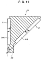
- the contact block 31 is provided with a columnar member 311 C having the axis parallel with the axial direction of the spindle 12 (the vertical direction in Fig. 11) and the columnar member 311D having the axis that forms an angle of ⁇ with the axis of the columnar member 311C.
- one contour line is the outermost protruding line L 1 of the columnar member 311 C and the other contour line is the outermost protruding line L2 of the columnar member 311D.
- the step measuring portion 312 is formed at the same height as the intersection C of the extension of line L1 and line L2.
- the contact block 31 since the side faces of the columnar members 311 C and 311D abut a workpiece during gap measurement, the workpiece is hardly damaged. Further, even in the case of measuring the inner diameter of a circular hole, since the side face of a columnar member can be inscribed in the inner wall of the circular hole, the inner side can be measured accurately. Furthermore, since a columnar member can be produced easily, the contact block 31 can also be produced easily and thus the production cost decreases.
- any gap measuring portion can be adopted as far as it is provided with one contour line parallel with the axial direction of the spindle and the other contour line that comes closer to the one contour line according as it is directed away from the case body toward one end of the spindle, and it is unnecessary that the other contour line is such a straight line (the generatrix of a cone in the first and second embodiments) as in the case of the aforementioned embodiments. That is, in the present invention, a contact point of such a special shape that the other contour line is a curved line may be adopted.
- the step and gap measuring instrument is configured so that the memory 16 can store the information on the special shape of the contact point with the preset switch 113D and also the computation controller 15 computes on the basis of the displacement of the spindle 12 and the information on the special shape of the contact point stored in the memory 16, computes the gap, and displays the results on the digital display 13, then an operator can directly read the gap even when the contact point is of a special shape.
- a step and gap measuring instrument of such a configuration makes it possible to select a contact point having a shape most suitable for measurement among contact points of various shapes in accordance with the shape of a workpiece at the time of the measurement and improve the usability in the measurement.
Landscapes
- Physics & Mathematics (AREA)
- General Physics & Mathematics (AREA)
- A Measuring Device Byusing Mechanical Method (AREA)
- Length-Measuring Instruments Using Mechanical Means (AREA)
Applications Claiming Priority (2)
| Application Number | Priority Date | Filing Date | Title |
|---|---|---|---|
| JP2004023039 | 2004-01-30 | ||
| JP2004023039A JP4509588B2 (ja) | 2004-01-30 | 2004-01-30 | 段差・隙間測定装置 |
Publications (2)
| Publication Number | Publication Date |
|---|---|
| EP1559989A1 true EP1559989A1 (de) | 2005-08-03 |
| EP1559989B1 EP1559989B1 (de) | 2015-08-19 |
Family
ID=34650843
Family Applications (1)
| Application Number | Title | Priority Date | Filing Date |
|---|---|---|---|
| EP05001675.7A Expired - Lifetime EP1559989B1 (de) | 2004-01-30 | 2005-01-27 | Stufen- und Abstandsmessvorrichtung |
Country Status (4)
| Country | Link |
|---|---|
| US (1) | US7100298B2 (de) |
| EP (1) | EP1559989B1 (de) |
| JP (1) | JP4509588B2 (de) |
| CN (1) | CN100392346C (de) |
Cited By (1)
| Publication number | Priority date | Publication date | Assignee | Title |
|---|---|---|---|---|
| CN106225648A (zh) * | 2016-07-22 | 2016-12-14 | 深圳天珑无线科技有限公司 | 工件斜面倾斜角度的测量方法 |
Families Citing this family (22)
| Publication number | Priority date | Publication date | Assignee | Title |
|---|---|---|---|---|
| US7216441B2 (en) * | 2005-07-29 | 2007-05-15 | Robert Alan Batora | Apparatus for measuring step height or depth against another surface |
| US7322121B1 (en) * | 2006-06-23 | 2008-01-29 | Ioan-Ilie Lupu | Device for checking chamfers and radii |
| US7730622B2 (en) * | 2006-08-02 | 2010-06-08 | Mccauley Kerry | Structural surface measuring and aligning apparatus and method |
| US7356939B1 (en) * | 2007-04-16 | 2008-04-15 | Honda Motor Co., Ltd. | System and method for measuring wind deflector height |
| KR101075637B1 (ko) * | 2009-04-23 | 2011-10-21 | 한국도로공사 | 도로포장용 단차측정장치 |
| JP5647907B2 (ja) * | 2011-01-31 | 2015-01-07 | 三菱電機ビルテクノサービス株式会社 | エレベータ用ドア隙間寸法測定装置 |
| JP5443522B2 (ja) * | 2012-01-25 | 2014-03-19 | 富士重工業株式会社 | 離間距離導出システムおよびシクネスゲージ |
| FR2990505B1 (fr) * | 2012-05-10 | 2014-05-16 | Peugeot Citroen Automobiles Sa | Procede et outil de controle de la conformite d'un montage entre un element ouvrant et un element de caisse d'un vehicule |
| TWM472833U (zh) * | 2013-08-13 | 2014-02-21 | Taiwan Power Testing Technology Co Ltd | 電子式焊道檢測規 |
| JP6608579B2 (ja) * | 2014-04-03 | 2019-11-20 | 株式会社ミツトヨ | 測定器 |
| US9651351B2 (en) * | 2015-07-27 | 2017-05-16 | Toyota Motor Engineering & Manufacturing North America, Inc. | Gap assessment tool |
| JP6222862B1 (ja) * | 2016-05-20 | 2017-11-01 | 東芝エレベータ株式会社 | 床面段差測定装置 |
| JP6727941B2 (ja) * | 2016-06-14 | 2020-07-22 | 株式会社ミツトヨ | 測定器 |
| CN105841593A (zh) * | 2016-06-15 | 2016-08-10 | 开滦(集团)有限责任公司唐山矿业分公司 | 对轮找正测量尺 |
| CN107063024B (zh) * | 2016-12-29 | 2019-08-27 | 神龙汽车有限公司 | 一种实现百分表测量间隙面差的检具结构及测量方法 |
| CN106949867A (zh) * | 2017-04-20 | 2017-07-14 | 厦门大学嘉庚学院 | 手持式高度差检测仪及其使用方法 |
| CN107655387A (zh) * | 2017-11-01 | 2018-02-02 | 杭州东华链条集团有限公司 | 梯级距测量装置 |
| KR102000999B1 (ko) * | 2018-07-10 | 2019-10-01 | (주)태경이엔씨 | 크랙 폭 측정 장치 및 방법 |
| CN110307818B (zh) * | 2019-06-21 | 2021-06-29 | 江苏理工学院 | 一种阶梯平面距离及孔深度测量装置 |
| CN110514162B (zh) * | 2019-08-09 | 2021-06-29 | 江苏理工学院 | 一种台阶深度测量工具 |
| CN114935301A (zh) * | 2022-06-01 | 2022-08-23 | 沈阳飞机工业(集团)有限公司 | 用于阶差测量的电子工具 |
| JP2024060543A (ja) * | 2022-10-19 | 2024-05-02 | 株式会社ミツトヨ | 小型測定器およびその使用方法 |
Citations (4)
| Publication number | Priority date | Publication date | Assignee | Title |
|---|---|---|---|---|
| US4606129A (en) | 1985-10-18 | 1986-08-19 | General Motors Corporation | Gap and flushness measuring tool |
| JPH07113603A (ja) * | 1993-10-18 | 1995-05-02 | Mitsutoyo Corp | 内側測定装置 |
| US5657550A (en) | 1994-10-12 | 1997-08-19 | Js Research And Development, Inc. | Hand-held gap and contour measuring gauge |
| EP0833132A2 (de) | 1996-09-26 | 1998-04-01 | Mitutoyo Corporation | Messuhr |
Family Cites Families (12)
| Publication number | Priority date | Publication date | Assignee | Title |
|---|---|---|---|---|
| US4345380A (en) * | 1981-03-06 | 1982-08-24 | Candid Logic, Inc. | Gap gauge |
| US4536964A (en) * | 1982-09-30 | 1985-08-27 | Lazes Richard J | Pipe thread gauge |
| US4473952A (en) * | 1982-12-16 | 1984-10-02 | Northern Telecom Limited | Two directional measuring devices |
| JPS61158811U (de) * | 1985-03-25 | 1986-10-02 | ||
| US4731935A (en) * | 1986-10-15 | 1988-03-22 | Struble James E | Contour and outline transducer gage assembly |
| JPH0519766Y2 (de) * | 1987-05-02 | 1993-05-25 | ||
| JPH0617041Y2 (ja) * | 1989-01-13 | 1994-05-02 | 日産自動車株式会社 | 寸法測定器 |
| US5551162A (en) * | 1994-10-12 | 1996-09-03 | Js Research And Development, Inc. | Hand-held gap and contour measuring gauge |
| JPH10170205A (ja) * | 1996-12-12 | 1998-06-26 | Fuji Photo Film Co Ltd | 間隙寸法検出方法および間隙寸法検出用積層体 |
| JP2002250601A (ja) | 2001-02-26 | 2002-09-06 | Showa Denko Kk | 隙間測定装置 |
| JP3738711B2 (ja) | 2001-08-03 | 2006-01-25 | 日産自動車株式会社 | 開口部隙間量測定ゲージおよびこの測定ゲージを使用した測定装置ならびに測定方法 |
| US6834439B2 (en) * | 2002-05-21 | 2004-12-28 | Mitutoyo Corporation | Measuring tool, encoder and producing method of encoder |
-
2004
- 2004-01-30 JP JP2004023039A patent/JP4509588B2/ja not_active Expired - Lifetime
-
2005
- 2005-01-27 EP EP05001675.7A patent/EP1559989B1/de not_active Expired - Lifetime
- 2005-01-27 US US11/044,435 patent/US7100298B2/en not_active Expired - Lifetime
- 2005-01-31 CN CNB2005100050482A patent/CN100392346C/zh not_active Expired - Lifetime
Patent Citations (4)
| Publication number | Priority date | Publication date | Assignee | Title |
|---|---|---|---|---|
| US4606129A (en) | 1985-10-18 | 1986-08-19 | General Motors Corporation | Gap and flushness measuring tool |
| JPH07113603A (ja) * | 1993-10-18 | 1995-05-02 | Mitsutoyo Corp | 内側測定装置 |
| US5657550A (en) | 1994-10-12 | 1997-08-19 | Js Research And Development, Inc. | Hand-held gap and contour measuring gauge |
| EP0833132A2 (de) | 1996-09-26 | 1998-04-01 | Mitutoyo Corporation | Messuhr |
Non-Patent Citations (1)
| Title |
|---|
| PATENT ABSTRACTS OF JAPAN vol. 1995, no. 08 29 September 1995 (1995-09-29) * |
Cited By (1)
| Publication number | Priority date | Publication date | Assignee | Title |
|---|---|---|---|---|
| CN106225648A (zh) * | 2016-07-22 | 2016-12-14 | 深圳天珑无线科技有限公司 | 工件斜面倾斜角度的测量方法 |
Also Published As
| Publication number | Publication date |
|---|---|
| US7100298B2 (en) | 2006-09-05 |
| CN100392346C (zh) | 2008-06-04 |
| EP1559989B1 (de) | 2015-08-19 |
| JP4509588B2 (ja) | 2010-07-21 |
| CN1648597A (zh) | 2005-08-03 |
| US20050166415A1 (en) | 2005-08-04 |
| JP2005214833A (ja) | 2005-08-11 |
Similar Documents
| Publication | Publication Date | Title |
|---|---|---|
| US7100298B2 (en) | Step and gap measuring instrument | |
| US4677755A (en) | Coordinate measuring instrument | |
| US20010029778A1 (en) | Surface texture measuring instrument, surface texture measuring method and stylus radius measuring instrument | |
| CN110132102B (zh) | 一种多功能测量工具及孔测量方法 | |
| EP1860398A2 (de) | Kalibrierungskörper | |
| US7043846B2 (en) | Reference gauge for calibrating a measuring machine and method for calibrating a measuring machine | |
| JP7076874B1 (ja) | 測定器 | |
| JP2022169398A (ja) | テストインジケータ | |
| JPH0829105A (ja) | ねじ測定装置 | |
| US3940854A (en) | Three axis precision measuring device | |
| JPH049701A (ja) | キー溝測定装置及びその使用方法 | |
| US20080189967A1 (en) | Standardizable level tool | |
| JP2004198350A (ja) | 厚み測定器 | |
| JP4492801B2 (ja) | 測定器具およびその製造方法 | |
| JP2611791B2 (ja) | 流量式空気マイクロメータ用プラグゲージおよびその製造方法 | |
| JP2002513918A (ja) | 穴の位置の計測に用いる計測補助具 | |
| US20080229604A1 (en) | Digital thickness gauge for both exterior dimension and tube or hollow wall thickness | |
| GB2622012A (en) | Hole perpendicularity probe | |
| JP2556792Y2 (ja) | ワーク測定装置 | |
| CN213812006U (zh) | 一种工件锥孔的测量装置 | |
| KR200182165Y1 (ko) | 구멍 깊이 측정값의 신뢰성을 향상시킨 계측장비 | |
| JP2786803B2 (ja) | パチンコ機械用釘間隔測定器 | |
| EP4450915A1 (de) | Vorrichtung zur messung der dicke einer gekrümmten batteriezelle mit bremssatteln für niedrigen messdruck und verfahren zur messung der dicke einer gekrümmten batteriezelle damit | |
| CN219083982U (zh) | 用于测量倒角的量具 | |
| CN114046713B (zh) | 适用于内外零件高度差的调平装置 |
Legal Events
| Date | Code | Title | Description |
|---|---|---|---|
| PUAI | Public reference made under article 153(3) epc to a published international application that has entered the european phase |
Free format text: ORIGINAL CODE: 0009012 |
|
| AK | Designated contracting states |
Kind code of ref document: A1 Designated state(s): AT BE BG CH CY CZ DE DK EE ES FI FR GB GR HU IE IS IT LI LT LU MC NL PL PT RO SE SI SK TR |
|
| AX | Request for extension of the european patent |
Extension state: AL BA HR LV MK YU |
|
| 17P | Request for examination filed |
Effective date: 20051208 |
|
| AKX | Designation fees paid |
Designated state(s): DE FR GB |
|
| 17Q | First examination report despatched |
Effective date: 20101115 |
|
| GRAP | Despatch of communication of intention to grant a patent |
Free format text: ORIGINAL CODE: EPIDOSNIGR1 |
|
| RIN1 | Information on inventor provided before grant (corrected) |
Inventor name: KIWADA, TAKEFUMI Inventor name: ISHII, MUNENORI |
|
| INTG | Intention to grant announced |
Effective date: 20150326 |
|
| GRAS | Grant fee paid |
Free format text: ORIGINAL CODE: EPIDOSNIGR3 |
|
| GRAA | (expected) grant |
Free format text: ORIGINAL CODE: 0009210 |
|
| AK | Designated contracting states |
Kind code of ref document: B1 Designated state(s): DE FR GB |
|
| REG | Reference to a national code |
Ref country code: GB Ref legal event code: FG4D |
|
| REG | Reference to a national code |
Ref country code: DE Ref legal event code: R096 Ref document number: 602005047268 Country of ref document: DE |
|
| REG | Reference to a national code |
Ref country code: FR Ref legal event code: PLFP Year of fee payment: 12 |
|
| REG | Reference to a national code |
Ref country code: DE Ref legal event code: R097 Ref document number: 602005047268 Country of ref document: DE |
|
| PLBE | No opposition filed within time limit |
Free format text: ORIGINAL CODE: 0009261 |
|
| STAA | Information on the status of an ep patent application or granted ep patent |
Free format text: STATUS: NO OPPOSITION FILED WITHIN TIME LIMIT |
|
| 26N | No opposition filed |
Effective date: 20160520 |
|
| REG | Reference to a national code |
Ref country code: FR Ref legal event code: PLFP Year of fee payment: 13 |
|
| REG | Reference to a national code |
Ref country code: FR Ref legal event code: PLFP Year of fee payment: 14 |
|
| PGFP | Annual fee paid to national office [announced via postgrant information from national office to epo] |
Ref country code: DE Payment date: 20240119 Year of fee payment: 20 Ref country code: GB Payment date: 20240123 Year of fee payment: 20 |
|
| PGFP | Annual fee paid to national office [announced via postgrant information from national office to epo] |
Ref country code: FR Payment date: 20240124 Year of fee payment: 20 |
|
| REG | Reference to a national code |
Ref country code: DE Ref legal event code: R071 Ref document number: 602005047268 Country of ref document: DE |
|
| REG | Reference to a national code |
Ref country code: GB Ref legal event code: PE20 Expiry date: 20250126 |
|
| PG25 | Lapsed in a contracting state [announced via postgrant information from national office to epo] |
Ref country code: GB Free format text: LAPSE BECAUSE OF EXPIRATION OF PROTECTION Effective date: 20250126 |