EP1560401A1 - Telefontastatur mit fugendichten Tasten - Google Patents
Telefontastatur mit fugendichten Tasten Download PDFInfo
- Publication number
- EP1560401A1 EP1560401A1 EP05290192A EP05290192A EP1560401A1 EP 1560401 A1 EP1560401 A1 EP 1560401A1 EP 05290192 A EP05290192 A EP 05290192A EP 05290192 A EP05290192 A EP 05290192A EP 1560401 A1 EP1560401 A1 EP 1560401A1
- Authority
- EP
- European Patent Office
- Prior art keywords
- keyboard
- keys
- recess
- telephone according
- orifices
- Prior art date
- Legal status (The legal status is an assumption and is not a legal conclusion. Google has not performed a legal analysis and makes no representation as to the accuracy of the status listed.)
- Withdrawn
Links
- 230000000295 complement effect Effects 0.000 claims abstract description 13
- 239000000463 material Substances 0.000 claims description 14
- 230000001419 dependent effect Effects 0.000 claims description 2
- 230000004913 activation Effects 0.000 description 2
- 239000006185 dispersion Substances 0.000 description 2
- 230000003213 activating effect Effects 0.000 description 1
- 238000004519 manufacturing process Methods 0.000 description 1
- 239000000203 mixture Substances 0.000 description 1
- 238000000465 moulding Methods 0.000 description 1
Images


Classifications
-
- H—ELECTRICITY
- H04—ELECTRIC COMMUNICATION TECHNIQUE
- H04M—TELEPHONIC COMMUNICATION
- H04M1/00—Substation equipment, e.g. for use by subscribers
- H04M1/02—Constructional features of telephone sets
- H04M1/23—Construction or mounting of dials or of equivalent devices; Means for facilitating the use thereof
-
- H—ELECTRICITY
- H04—ELECTRIC COMMUNICATION TECHNIQUE
- H04M—TELEPHONIC COMMUNICATION
- H04M1/00—Substation equipment, e.g. for use by subscribers
- H04M1/02—Constructional features of telephone sets
- H04M1/0202—Portable telephone sets, e.g. cordless phones, mobile phones or bar type handsets
-
- H—ELECTRICITY
- H01—ELECTRIC ELEMENTS
- H01H—ELECTRIC SWITCHES; RELAYS; SELECTORS; EMERGENCY PROTECTIVE DEVICES
- H01H2217/00—Facilitation of operation; Human engineering
- H01H2217/006—Different feeling for different switch sites
-
- H—ELECTRICITY
- H04—ELECTRIC COMMUNICATION TECHNIQUE
- H04M—TELEPHONIC COMMUNICATION
- H04M1/00—Substation equipment, e.g. for use by subscribers
- H04M1/02—Constructional features of telephone sets
- H04M1/0202—Portable telephone sets, e.g. cordless phones, mobile phones or bar type handsets
- H04M1/0279—Improving the user comfort or ergonomics
- H04M1/0283—Improving the user comfort or ergonomics for providing a decorative aspect, e.g. customization of casings, exchangeable faceplate
-
- H—ELECTRICITY
- H04—ELECTRIC COMMUNICATION TECHNIQUE
- H04M—TELEPHONIC COMMUNICATION
- H04M1/00—Substation equipment, e.g. for use by subscribers
- H04M1/72—Mobile telephones; Cordless telephones, i.e. devices for establishing wireless links to base stations without route selection
- H04M1/724—User interfaces specially adapted for cordless or mobile telephones
- H04M1/72403—User interfaces specially adapted for cordless or mobile telephones with means for local support of applications that increase the functionality
Definitions
- the present invention relates to telephones having a keypad joined keys.
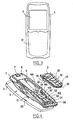
- FIG. 1 represents an exploded view of a known telephone comprising a shell forming a housing and divided into an anterior part 1 and a part posterior 2 cooperating with each other.
- anterior and posterior 2 cooperating with each other.
- the terms "anterior” and “posterior” are taken in a sense normal operation of the phone, the front part reference to the part generally containing the main elements operating the phone, a possible screen, as well as the speaker.
- a screen element 4 is disposed on the front part 1 of the phone.
- a screen 4 is optional and applies advantageously to mobile phones.
- a keyboard 3 is mounted between the front part 1 and the rear part 2 the shell of the phone, that is to say in the housing of the phone.
- the keyboard 3 has keys 30.
- Each key 30 comprises on the one hand an anterior part 33 in protruding relative and material coming on a plate 34 common to 30.
- the plate 34 is preferably made of plastic flexible.
- Each front portion 33 is adapted to cooperate with orifices Formed in the anterior part 1 of the hull and is capable of filling a orifice 10.
- Each key 30 has on the other hand a posterior portion 32 preferably comprising actuators able to cooperate with electronic means disposed on the rear portion 2 of the shell.
- the keyboard 3 is mounted below the anterior part 1 of the hull. So once the keyboard 3 mounted in the shell, a user of the phone can access keys 30 in protruding into the orifices 10 of the front part 1. The pressure of the keys 30 allows phone activation and dialing by example.
- the front 1 and back 2 parts of the phone shell are preferentially removable relative to each other.
- means 12 forming hooks on the front part 1 cooperate with means 22 located opposite the rear part 2 to form a mechanical clip that allows a user to separate the anterior part 1 and the posterior part 2 easily, and this any time.
- keyboard 3 is also removable phone once the anterior 1 and posterior 2 parts are separated one of the other.
- Figure 2 shows an exploded view of an example of a mode of realization of a known phone also comprising a shell forming housing and divided into an anterior portion 1 and a rear portion 2, and a keyboard 3 with touching keys 30, the keyboard being known to the skilled person.
- a screen element 4 is advantageously arranged on the front part 1 of the phone.
- the keyboard 3 is disposed between the anterior portion 1 and posterior 2 from the phone shell.
- anterior part 1 no longer has a series of orifices but only one large aperture 10 for the keyboard 3 with 30 joined keys.
- the keyboard 3 mounts as in the figure 1 below the front part 1 of the hull.
- the keyboard 3 has on its periphery means 31 able to cooperate with means 13 on the front part 1 of the hull.
- Means 31 and 13 may be of the rib / groove type. Cooperation means 31 and 13 prevents the keyboard 3 can come out of the hull.
- the rear part 2 comprises fastening means 21 cooperating with means 11 on the front part 1.
- the fastening means 21 are for example screws cooperating with threaded bores 11. This mode fastening strengthens the rigidity and overall strength of the phone.
- the anterior parts 1 and 2 are not in this case directly removable relative to each other.
- a user of the phone can have access to the front 33 of the 30 keys and dials for example, the keys 30 having in a posterior portion 32 actuator means capable of activating electronic means disposed on the rear part 2 of the shell, in the case.
- the large opening 10 generates a fragility and a lack of rigidity of the anterior part 1.
- the anterior part 1 is therefore difficult to handle during a phase of industrial assembly. It breaks easily.
- the anterior part 1 is also easily broken when the use of the phone, especially if the phone falls.
- fastening means 21 and 11 more important between the parts of the hull on the one hand and means 31 and 13 between the keyboard and the hull on the other hand must be provided, which limits the removability of the part front and / or phone keypad.
- the front part 1 can break easily when handled by a user.
- the invention proposes to overcome at least one of the disadvantages of telephones of the prior art.
- One of the aims of the invention is to propose a telephone whose keyboard has touching keys and at least the front part of which is rigid.
- One of the aims of the invention is notably to propose a telephone whose front part is easily adaptable to an industrial assembly.
- Another object of the invention is to propose a telephone which has a housing whose at least the front part is easily removable.
- One of the aims of the invention is also to propose a telephone whose anterior part is easily manipulated by a user without risk of being broken.
- Another aim of the invention is to propose a telephone whose keyboard has touch keys and is easily removable.
- the invention proposes a telephone according to claim 1.
- the invention has many advantages.
- the external appearance of the keyboard surface remains substantially flat. he there is no distortion when handling the phone. There's no overlapping keys.
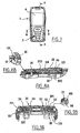
- FIG. 4 schematically represents an exploded view of a mode of possible embodiment of a telephone according to the invention.
- the phone mainly comprises a housing 5 having a external surface 6 and a keyboard 3 with touches 30 joined.
- the surface 6 has a recess 100 for receiving the keyboard 3.
- the recess 100 is a recess of material coming on the housing 5.
- the recess 100 is preferentially defined on a zone front of the housing 5.
- anterior area referring to the area with a screen 4 and holes 7 a speaker phone.
- Screen 4 is optional and can be provided telephones according to the invention not including such a screen 4.
- the recess 100 is preferably located on a zone adjacent to an area with screen 4.
- the recess 100 has a wall 102 of extension bottom, having orifices 101, and substantially parallel to the surface of the screen 4 or substantially parallel to most of the outer surface of the front zone of the housing 5.
- Figure 5 shows a front view of the front area of the housing 5.
- the recess 100 also has side walls 103 extending substantially perpendicular to the bottom wall 102.
- the outer contour of the recess 100 defined by the walls lateral 103 is complementary to the outer contour of the keyboard 3.
- the wall 102 is able to cooperate with a posterior surface 32 of the keyboard 3.
- the interior volume defined in recess 100 corresponds substantially to the volume of the keyboard 3.
- the keyboard 3 is adapted to be mounted in the recess 100. It comes lodge in the recess 100 in a direction going from the area front housing 5 to the rear area of the housing 5. In the position mounted, an earlier surface 33 of the keyboard is substantially at the level of screen 4 or at most of the outer surface of the area front of the housing 5.
- the keyboard 3 comprises means 35 and 36 for fixing complementary means 105 and 106 located in the recess 100.
- the means 35 and 36 are material on the keyboard 3, the means 105 and 106 came from material on the recess 100.
- the cooperation of the means 35 and 105 on the one hand and the cooperation of means 36 and 106 on the other hand are able to fix the keyboard 3 in the recess 100.
- the keyboard 3 comprises an outer surface 33 located on the front part of the keyboard 3 and forming the touching keys 30.
- a surface 33 is preferentially made of plastic material.
- the plastic is preferentially rigid.
- the keys 30 are joined, which means that there is no material of the housing between the keys 30, and that they are tight relative to each other to others.
- the keys 30 have posterior portions 34.
- the keyboard 3 also optionally includes a surface 330 forming light cache.
- a surface 330 is made of a material opaque and helps to further guide a possible light in from the interior of the housing 5 and to the keys 30 of the keyboard 3.
- the surface 330 thus has holes 332 complementary parts of the posterior parts 34 of the keys 30. Of the material 333 between the holes 332 can hide the light coming from inside the case.
- the keyboard 3 also includes a surface 331, also making possibly serve as a light guide, and if necessary to to further guide a light coming from inside the housing 5 and to destination of the keys 30 of the keyboard 3, avoiding a dispersion of the light between the keys 30.
- the surface 331 solidifies the entire keyboard 3.
- the surface 331 is preferably made of rigid plastic material.
- the surface 331 also makes it possible to guide the posterior portion 34 30. It thus has holes 334 complementary to the posterior portions 34 of the keys 30.
- Material 335 between orifices 334 is advantageously opaque in case of absence of surface 330. Opacity can be obtained due to the composition of the opaque plastic surface 331, or by silkscreen on the surface 331.
- the surface 331 also comprises the means 35 and 36 for fixing keyboard 3 in the recess 100.
- the means 35 and 36 for fixing the keyboard 3 form respectively pins 37 and 38.
- the pins 37 and 38 have come of material on the surface 331.
- the keyboard 3 finally has a surface 32 comprising the actuators 320 related to the keys 30.
- the surface 32 is preferably plastic flexible.
- the surface 32 has portions of protrusions 321 on the anterior portion of the layer 32.
- the protrusions 321 are complementary holes 334 and 332 of the respective surfaces 330 and 331, and cooperate with the rear portions 34 of the keys 30.
- the projections 321 and the posterior portions 34 are advantageously glued together. Mechanical cooperation or plastic deformation are also possible to co-operate protrusions 321 and parts 34.
- the keys 30 are set in cooperation individually on the protrusions 321.
- the surface 33 is therefore formed by the set of individual keys.
- the surface 32 has on its rear part the actuators 320 adapted to cooperate with the orifices 101 of the wall 102 of the recess 100, once the keyboard 3 is in place in the recess 100, as the Figure 7.
- Actuators are typically excrescences oblong material coming on the surface 32.
- the actuators 320 are visible in Figures 8A and 9A.
- the actuators 320 are able to transmit movements of the keys 30 through the orifices 101.
- a solicitation movement of the keys 30 of the surface 33 is therefore transmitted to an electronic part in the case for the dialing and activation of the phone for example.
- the bottom wall 102 has at least one orifice 101 at the right each actuator 320. It may include more for reasons of molding and manufacturing or assembly.
- the keyboard 3 is removable from the recess 100. A The user can easily customize his keyboard at any time.
- FIG. 8B thus shows that the lug 37 cooperates with a projecting edge 106 of the recess 100 to form a mechanical hook.
- the ergot 37 is removably mounted in the means 106.
- the keyboard 3 has two lugs 37 located at the bottom of the keyboard 3, to the opposite of the screen 4. The two lugs 37 can of course be located in other places.
- FIG. 9B shows that the lug 38 cooperates with a projecting edge 105 lateral of the recess 100 to form a mechanical clip.
- the ergot 38 is therefore removably mounted in the means 105.
- the keyboard 3 has two pins 38, one on each side of the keyboard 3.
- the housing 5 has two parts 1 and 2 complementary to each other, an earlier part 1 and a part posterior 2.
- Each part 1 and 2 comprises respective fixing means 15 and 25, complementary to each other.
- the cooperation of the means 15 and 25 is able to fix the two parts 1 and 2 of the housing 5 with each other.
- This cooperation can materialize by complementary mechanical means, for example of the type hook 15 / groove 25, as shown in Figure 4.
- the two parts 1 and 2 are removable one of the other. A user can customize his case or have access to the inside of the case at any moment, easily.
- the housing 5 is preferably made of plastic, but can be in any other matter.
- the housing 5 has a screen 4 display.
- a telephone according to the invention may however not include such a screen 4.
- the phone may be of the mobile terminal type. he can however, be of a different type, such as a terminal of Wireless European Telecommunications or "Digital European Cordless Telecommunication (DECT) ".
- DECT Digital European Cordless Telecommunication
- the invention provides many advantages.
- the wall 102 stiffens including the housing of the phone, while allowing the establishment of a keyboard with touching keys.
- the case is stronger and stiffer. It is therefore easier mountable or industrially manipulable.
- the keyboard is advantageously removable. In this case, the case is less easily broken when handled by a user.
Landscapes
- Engineering & Computer Science (AREA)
- Signal Processing (AREA)
- Telephone Set Structure (AREA)
Applications Claiming Priority (2)
| Application Number | Priority Date | Filing Date | Title |
|---|---|---|---|
| FR0400792A FR2865601B1 (fr) | 2004-01-28 | 2004-01-28 | Telephone comportant un clavier a touches jointives |
| FR0400792 | 2004-01-28 |
Publications (1)
| Publication Number | Publication Date |
|---|---|
| EP1560401A1 true EP1560401A1 (de) | 2005-08-03 |
Family
ID=34639796
Family Applications (1)
| Application Number | Title | Priority Date | Filing Date |
|---|---|---|---|
| EP05290192A Withdrawn EP1560401A1 (de) | 2004-01-28 | 2005-01-28 | Telefontastatur mit fugendichten Tasten |
Country Status (2)
| Country | Link |
|---|---|
| EP (1) | EP1560401A1 (de) |
| FR (1) | FR2865601B1 (de) |
Families Citing this family (1)
| Publication number | Priority date | Publication date | Assignee | Title |
|---|---|---|---|---|
| JP4394047B2 (ja) | 2005-08-05 | 2010-01-06 | 信越ポリマー株式会社 | キーフレームおよび押釦スイッチ用カバー部材 |
Citations (4)
| Publication number | Priority date | Publication date | Assignee | Title |
|---|---|---|---|---|
| EP1156643A2 (de) * | 2000-05-16 | 2001-11-21 | SAMSUNG ELECTRONICS Co. Ltd. | Tasten mit geneigtem Profil , Tastenanordnung mit geneigtem Profil und Endgerät mit einer solchen Anordnung |
| US20020094838A1 (en) * | 2001-01-12 | 2002-07-18 | Hsiang-Hua Wang | Structure of film type keyboard of cellular phones |
| GB2371266A (en) * | 2000-12-29 | 2002-07-24 | Nokia Mobile Phones Ltd | A casing for a portable communication device |
| US20030143961A1 (en) * | 2002-01-30 | 2003-07-31 | Morris Humphreys | Elastomeric enclosure |
-
2004
- 2004-01-28 FR FR0400792A patent/FR2865601B1/fr not_active Expired - Fee Related
-
2005
- 2005-01-28 EP EP05290192A patent/EP1560401A1/de not_active Withdrawn
Patent Citations (4)
| Publication number | Priority date | Publication date | Assignee | Title |
|---|---|---|---|---|
| EP1156643A2 (de) * | 2000-05-16 | 2001-11-21 | SAMSUNG ELECTRONICS Co. Ltd. | Tasten mit geneigtem Profil , Tastenanordnung mit geneigtem Profil und Endgerät mit einer solchen Anordnung |
| GB2371266A (en) * | 2000-12-29 | 2002-07-24 | Nokia Mobile Phones Ltd | A casing for a portable communication device |
| US20020094838A1 (en) * | 2001-01-12 | 2002-07-18 | Hsiang-Hua Wang | Structure of film type keyboard of cellular phones |
| US20030143961A1 (en) * | 2002-01-30 | 2003-07-31 | Morris Humphreys | Elastomeric enclosure |
Also Published As
| Publication number | Publication date |
|---|---|
| FR2865601A1 (fr) | 2005-07-29 |
| FR2865601B1 (fr) | 2006-04-07 |
Similar Documents
| Publication | Publication Date | Title |
|---|---|---|
| US9674975B2 (en) | Protective enclosure for touch screen device | |
| USD496639S1 (en) | Cellular telephone | |
| EP0871313A1 (de) | Kommunikationsgerät insbesondere für Telefonie, welches einen akustischen Leiter verwendet um ein Mikrofon mit der Aussenseite des Geräts zu verbinden | |
| FR2913842A1 (fr) | Touche, dispositif de saisie et dispositif mobile equipe de ceux-ci | |
| BE1018405A5 (fr) | Plaques de base pour dispositifs electriques encastrables. | |
| EP1560401A1 (de) | Telefontastatur mit fugendichten Tasten | |
| USD566095S1 (en) | Cellular telephone | |
| EP3727941B1 (de) | Verkleidungselement für die externe säule eines fahrzeugs sowie herestellungsverfahren für ein derartiges element | |
| CH714635A1 (fr) | Pièce d'horlogerie à sonnerie. | |
| FR2871832A1 (fr) | Mecanisme de verrouillage et son procede d'actionnement | |
| USD543527S1 (en) | Folder-type cellular phone with digital camera | |
| FR2643028A1 (fr) | Cassette a miroir, notamment pour pare-soleil d'un habitacle d'automobile et procede de fabrication | |
| JP2007068004A (ja) | 筐体発光構造 | |
| JP2008052124A (ja) | 保護パネルの取付構造及び携帯型電子機器 | |
| USD543180S1 (en) | Folder-type cellular phone with digital camera | |
| WO2009156203A1 (en) | A cover | |
| USD543181S1 (en) | Folder-type cellular phone with digital camera | |
| JP4633285B2 (ja) | キー操作装置 | |
| FR2865708A1 (fr) | Module de commande d'un ouvrant de vehicule. | |
| KR20110113334A (ko) | 거울이 구비된 셀룰러폰 및 셀룰러폰에 장착가능한 거울 결합체 | |
| FR2819946A1 (fr) | Cadre avec socle pour dispositif electrique | |
| EP3636492B1 (de) | Kraftfahrzeugeinheit, die ein leuchtgewebe umfasst | |
| JP3805615B2 (ja) | 陶磁器製壁掛 | |
| EP0426584A1 (de) | Vorrichtung zum Erkennen des Abhebens eines Telefonhörers | |
| EP1467145B1 (de) | Signalleuchte für Fahrzeuge |
Legal Events
| Date | Code | Title | Description |
|---|---|---|---|
| PUAI | Public reference made under article 153(3) epc to a published international application that has entered the european phase |
Free format text: ORIGINAL CODE: 0009012 |
|
| AK | Designated contracting states |
Kind code of ref document: A1 Designated state(s): AT BE BG CH CY CZ DE DK EE ES FI FR GB GR HU IE IS IT LI LT LU MC NL PL PT RO SE SI SK TR |
|
| AX | Request for extension of the european patent |
Extension state: AL BA HR LV MK YU |
|
| 17P | Request for examination filed |
Effective date: 20050905 |
|
| AKX | Designation fees paid |
Designated state(s): AT BE BG CH CY CZ DE DK EE ES FI FR GB GR HU IE IS IT LI LT LU MC NL PL PT RO SE SI SK TR |
|
| RAP1 | Party data changed (applicant data changed or rights of an application transferred) |
Owner name: SAGEM COMMUNICATION |
|
| STAA | Information on the status of an ep patent application or granted ep patent |
Free format text: STATUS: THE APPLICATION IS DEEMED TO BE WITHDRAWN |
|
| 18D | Application deemed to be withdrawn |
Effective date: 20061031 |