EP1568942A1 - Brûleur à prémélange et procédé pour brûler un gaz pauvre - Google Patents
Brûleur à prémélange et procédé pour brûler un gaz pauvre Download PDFInfo
- Publication number
- EP1568942A1 EP1568942A1 EP04004137A EP04004137A EP1568942A1 EP 1568942 A1 EP1568942 A1 EP 1568942A1 EP 04004137 A EP04004137 A EP 04004137A EP 04004137 A EP04004137 A EP 04004137A EP 1568942 A1 EP1568942 A1 EP 1568942A1
- Authority
- EP
- European Patent Office
- Prior art keywords
- combustion
- gas
- air
- premix
- burner
- Prior art date
- Legal status (The legal status is an assumption and is not a legal conclusion. Google has not performed a legal analysis and makes no representation as to the accuracy of the status listed.)
- Withdrawn
Links
Images
Classifications
-
- F—MECHANICAL ENGINEERING; LIGHTING; HEATING; WEAPONS; BLASTING
- F23—COMBUSTION APPARATUS; COMBUSTION PROCESSES
- F23R—GENERATING COMBUSTION PRODUCTS OF HIGH PRESSURE OR HIGH VELOCITY, e.g. GAS-TURBINE COMBUSTION CHAMBERS
- F23R3/00—Continuous combustion chambers using liquid or gaseous fuel
- F23R3/02—Continuous combustion chambers using liquid or gaseous fuel characterised by the air-flow or gas-flow configuration
- F23R3/04—Air inlet arrangements
- F23R3/10—Air inlet arrangements for primary air
- F23R3/12—Air inlet arrangements for primary air inducing a vortex
- F23R3/14—Air inlet arrangements for primary air inducing a vortex by using swirl vanes
-
- F—MECHANICAL ENGINEERING; LIGHTING; HEATING; WEAPONS; BLASTING
- F23—COMBUSTION APPARATUS; COMBUSTION PROCESSES
- F23D—BURNERS
- F23D14/00—Burners for combustion of a gas, e.g. of a gas stored under pressure as a liquid
- F23D14/46—Details
- F23D14/48—Nozzles
- F23D14/58—Nozzles characterised by the shape or arrangement of the outlet or outlets from the nozzle, e.g. of annular configuration
- F23D14/583—Nozzles characterised by the shape or arrangement of the outlet or outlets from the nozzle, e.g. of annular configuration of elongated shape, e.g. slits
-
- F—MECHANICAL ENGINEERING; LIGHTING; HEATING; WEAPONS; BLASTING
- F23—COMBUSTION APPARATUS; COMBUSTION PROCESSES
- F23R—GENERATING COMBUSTION PRODUCTS OF HIGH PRESSURE OR HIGH VELOCITY, e.g. GAS-TURBINE COMBUSTION CHAMBERS
- F23R3/00—Continuous combustion chambers using liquid or gaseous fuel
- F23R3/28—Continuous combustion chambers using liquid or gaseous fuel characterised by the fuel supply
- F23R3/286—Continuous combustion chambers using liquid or gaseous fuel characterised by the fuel supply having fuel-air premixing devices
-
- F—MECHANICAL ENGINEERING; LIGHTING; HEATING; WEAPONS; BLASTING
- F23—COMBUSTION APPARATUS; COMBUSTION PROCESSES
- F23R—GENERATING COMBUSTION PRODUCTS OF HIGH PRESSURE OR HIGH VELOCITY, e.g. GAS-TURBINE COMBUSTION CHAMBERS
- F23R2900/00—Special features of, or arrangements for continuous combustion chambers; Combustion processes therefor
- F23R2900/00002—Gas turbine combustors adapted for fuels having low heating value [LHV]
Definitions
- the invention relates to a premix burner for combustion a low calorie combustible gas, in particular a synthesis gas.
- the invention further relates to a method for the combustion of a low calorific fuel gas.
- a burner for gaseous fuels, in particular used in a gas turbine plant is, for example known from DE 42 12 810 A1. It can be seen that Combustion air through an air-ring channel system and fuel fed through another annular channel system of combustion become. This is a high-calorie fuel (Natural gas or fuel oil) from the fuel channel into the air duct injected, either directly or formed as a hollow blades Swirl blades.
- a high-calorie fuel Natural gas or fuel oil
- the combustible constituents of synthesis gas are essentially carbon monoxide and hydrogen.
- the burner in the gas turbine associated combustion chamber must then be designed as a two- or multi-fuel burner, both with the synthesis gas and with the second fuel, such as natural gas or fuel oil can be applied as needed.
- the respective fuel is supplied via a fuel passage in the burner of the combustion zone.
- the calorific value of the synthesis gas is about five to ten times smaller compared to the calorific value of natural gas.
- Main constituent in addition to CO and H 2 are inert components such as nitrogen and / or water vapor and possibly also carbon dioxide. Due to the low calorific value consequently high volume flows of fuel gas must be supplied through the burner of the combustion chamber. This has the consequence that one or more separate fuel passages must be made available for the combustion of low calorific fuels - such as synthesis gas.
- Such a multi-pass burner which is also suitable for synthesis gas operation, is disclosed for example in EP 1 227 920 A1.
- premix combustion In view of increasingly stringent requirements on the output Of nitrogen oxides, premix combustion also gains The combustion of low calorific gases is becoming increasingly important.
- the object of the invention is therefore a premix burner for Indicate combustion of a low calorific fuel gas.
- a Another object of the invention is to specify a Process for the combustion of a low calorific fuel gas.
- the first object is achieved by a premix burner for burning a low calorie Fuel gas, with one extending along a burner axis
- Premix air duct can be supplied via the combustion air is, and arranged with a in the premix air duct Swirling device, wherein in the flow direction of the combustion air downstream of the swirl device an injection device is arranged for the low calorific fuel gas.
- the invention is based on the consideration that to ensure a low-emission operation the mixture of Fuel and combustion air is of particular importance. Temperature peaks can only be as homogeneous as possible Mixture be avoided. As with low calorific fuel gases high volume flows of fuel gas are involved with the Combustion air to mix, here presented the solution of Mixed task presents the experts with special challenges the constructive design of such burner.
- the synthesis gas premix burner of the invention is used for the first time proposed a burner concept, which pollutant emissions Related advantages of premixing also for low calorie synthesis gas as fuel makes applicable.
- the injection device downstream of the twisting device takes place the injection of undiluted or partially diluted low calorie Fuel gas in the already twisted mass flow.
- the spatial area downstream of the twisting device takes place thereby a largely homogeneous mixing of the synthesis gas and the twisted air mass flow.
- the Combustion of the premixed fuel gas-air mixture takes place downstream of the burner at one of the premixed air ratios corresponding temperature.
- Premix flame can - especially in the partial load range - a small partial mass flow of the low calorie combustible gas previously separated and in the combustion chamber via a in the diffusion mode operated sustaining flame, e.g. about 5% up to 20% of the total volume flow of fuel gas ..
- the swirl device are sufficiently large volume flows of low calorific fuel gas miscible with the combustion air, where extremely good mixing results can be achieved are. This has a particularly advantageous effect on the pollutant balance from the premix burner.
- Another advantage is that the proven premix combustion concept for high-calorie fuels such as natural gas or Oil can be taken over unchanged, so that any lengthy Optimizations and / or design changes not necessary. That is, it is possible a conventional combustion system, designed for high calorific fuels is, by means of fluidically coupled to the air duct Injection device through an additional fuel passage for low calorific fuel gases, and indeed without the constructive implementation an adverse effect on the existing conventional combustion system would have, e.g. with regard to occurring pressure losses.
- the premix burner with both the synthesis gas for example, from coal, industrial residues or Waste is generated, as well as with a secondary fuel, such as e.g. Natural gas or oil.
- a secondary fuel such as e.g. Natural gas or oil.
- the premix burner burns accordingly the set air ratio at much lower temperatures; which ultimately leads to a minimization of the thermal Nitrogen oxide formation during combustion of the low calorie Fuel gas leads.
- the injection device a plurality of fuel gas inlet ports on, which open into the premix air duct.
- the injection device has a gas distribution ring which surrounds the premix air passage radially outward.
- the premix air duct is preferred as an annular channel formed, which has an outer channel wall, with a variety of holes interspersed with the gas distribution ring in fluid communication. This will It achieves that over the full circumference of the ring channel one Injection of low calorific fuel gas into the twisted Combustion air is ensured.
- the volume flow of low calorific fuel gas is the Diameter of the hole, their number and their distribution the outer duct wall should be designed accordingly.
- the outer channel wall tapers cone-like in the flow direction of the combustion air. Due to the injection of the low calorific fuel gas through the holes introduced into the outer cone to any additional negative influence on the air flow Built-in components for the injection device are dispensed with, allowing the operation even with conventional fuels (Natural gas or fuel oil) without restriction if necessary is possible.
- Particularly preferred embodiment is the premix burner in a combustion chamber, for example in an annular combustion chamber, used.
- a combustion chamber is advantageous designed as a combustion chamber of a gas turbine, for example as an annular combustion chamber of a stationary gas turbine.
- the object directed to the method is according to the invention solved by a method of burning a low calorie Fuel gas, in which the combustion air imparted a twist, low calorific fuel gas into the twisted combustion air injected and mixed with this, and the mixture is burned.
- This process is a particularly homogeneous combustion mixture achievable, with high volume flows of low calorie Fuel gas are miscible with the combustion air.
- This is advantageously undiluted or partially diluted low calorific fuel gas into the twisted combustion air injected.
- the method is preferably in operation a gas turbine burner, wherein a synthesis gas, which is a low calorie fuel, burned in premix operation.
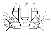
- the premix burner 1 shows a premix burner 1, which is approximately rotationally symmetrical with respect to a burner axis 12.
- One along the burner axis 12 directed pilot burner 9 with a Fuel supply channel 8 and this concentrically enclosing Air supply annular channel 7 is surrounded concentrically from a fuel ring channel 3.
- This fuel ring channel 3 is partially concentrically enclosed by a premixed air channel 2.
- the premix air channel 2 is the annular channel 14th formed, which has an outer channel wall 15.
- a swirl device forms. At least one of these swirl blades 5 is as Hollow blade 5a formed. It points one by several small openings formed inlet 6 for a fuel supply on.
- the hollow blade 5a is for the supply of high calorie fuel 11, e.g. Natural gas or fuel oil, designed.
- the fuel ring channel 3 opens into this hollow blade 5a.
- the premix burner 1 can via the pilot burner 9 as a diffusion burner operate. Usually he is but as Premix burners are used, that is, fuel and air first mixed and then sent to combustion. there the pilot burner 9 serves to maintain a pilot flame, combustion during premix burner operation at a possibly changing fuel-air ratio stabilized.
- combustion air 10 and the high calorific fuel 11 mixed in premix air channel 2 and then fed to the combustion.
- high-calorie fuel 11th from the fuel ring channel 3 in a hollow blade 5a of the Swirl vane wreath 5 and from there over the inlet 6 introduced into the combustion air 10 in the premix air channel 2.
- the premix burner 1 of the invention is beyond optionally also the combustion of a low calorific fuel gas SG, for example, a synthesis gas from a coal gasification process, possible.
- a low calorific fuel gas SG for example, a synthesis gas from a coal gasification process
- the injection device 13 comprises a plurality from inlet openings 16 for the fuel gas SG.
- the inlet openings 16 open into the premix air channel 2.
- the injection device 13 has a gas distribution ring 17, the surrounds the premix air channel 2 radially outward.
- low calorific gas SG fully in the annular channel 14 formed as a premixing air duct second downstream of the swirl device 5 in the distributed combustion air flow 10 is injectable.
- the outer channel wall 15 of Ring channel 14 is here with a variety of holes interspersed with the gas distribution ring 17 in fluid communication stand. In this way is through the gas distribution ring 17 also ensures a distributor function, so that low calorific gas SG with the required Pressure and flow rate provided and by the variety of holes in the outer channel wall 15 of the twisted Combustion air 10 can be mixed.
- it is a particularly homogeneous and uniform one Mixing of combustion air 10 with the low calorie Fuel gas SG reached.
- Fuel gas SG can be supplied for the synthesis gas pre-mixing operation.
- the outer channel wall 15 tapers.
- the premix burner 1 for combustion of a low calorific gas SG is in a combustion chamber of a gas turbine, for example a Ring combustion chamber of a stationary gas turbine used.
- premix burner 1 of the invention is an optional Operation with a synthesis gas from a gasification device or a secondary or substitute fuel possible, since the premix burner 1 designed as a two- or multi-fuel burner is that with both low calorific fuel gas SG as well with high calorie fuel 11, e.g. Natural gas or fuel oil, can be applied.
- high calorie fuel e.g. Natural gas or fuel oil
- Fuel gas SG is the combustion air 10 imparted a twist and the low calorific fuel gas SG in the twisted Combustion air 10 injected and mixed with this. This mixture is then burned. It can also teilverPhynstes low-calorie fuel gas SG in the twisted Combustion air 10 are injected.
- low calorie Fuel gas SG is advantageously a gasifier fossil fuel, especially gasified coal from a Gasification device, used.
- the premix burner 1 is particularly advantageous a synthesis gas operation in a Gas turbine feasible.
- the main advantage of the premix burner according to the invention 1 and the described method for combustion of a low calorific fuel SG is that the proven Premix combustion concept for natural gas and oil (high calorific Fuels) can be taken over unchanged.
- high calorific Fuels high calorific Fuels
- the premix burner 1 is only through an additional fuel passage for low calorie Brenngase SG expands without the constructive implementation a significant influence on conventional operation combustion system with high calorific fuels.
- the proposed construction allows particularly favorable Mixing properties of the low calorific gas SG with the combustion air 10, with a sufficiently large Throughput (volume flow) of synthesis gas SG of the combustion process can be supplied.
Landscapes
- Engineering & Computer Science (AREA)
- Chemical & Material Sciences (AREA)
- Combustion & Propulsion (AREA)
- Mechanical Engineering (AREA)
- General Engineering & Computer Science (AREA)
Priority Applications (6)
| Application Number | Priority Date | Filing Date | Title |
|---|---|---|---|
| EP04004137A EP1568942A1 (fr) | 2004-02-24 | 2004-02-24 | Brûleur à prémélange et procédé pour brûler un gaz pauvre |
| CN200580005907.6A CN100473905C (zh) | 2004-02-24 | 2005-02-15 | 用于燃烧低热量燃烧气体的预混合燃烧器以及方法 |
| US10/590,379 US7448218B2 (en) | 2004-02-24 | 2005-02-15 | Premix burner and method for burning a low-calorie combustion gas |
| EP05708014A EP1723369B1 (fr) | 2004-02-24 | 2005-02-15 | Bruleur a premelange et procede pour bruler un gaz pauvre |
| PCT/EP2005/050656 WO2005080878A1 (fr) | 2004-02-24 | 2005-02-15 | Bruleur de premelange et procede pour realiser la combustion d'un gaz de combustion faiblement calorifique |
| ES05708014T ES2287902T3 (es) | 2004-02-24 | 2005-02-15 | Quemador de premezcla asi como procedimiento para la combustion de un combustible gaseoso pobre. |
Applications Claiming Priority (1)
| Application Number | Priority Date | Filing Date | Title |
|---|---|---|---|
| EP04004137A EP1568942A1 (fr) | 2004-02-24 | 2004-02-24 | Brûleur à prémélange et procédé pour brûler un gaz pauvre |
Publications (1)
| Publication Number | Publication Date |
|---|---|
| EP1568942A1 true EP1568942A1 (fr) | 2005-08-31 |
Family
ID=34745867
Family Applications (2)
| Application Number | Title | Priority Date | Filing Date |
|---|---|---|---|
| EP04004137A Withdrawn EP1568942A1 (fr) | 2004-02-24 | 2004-02-24 | Brûleur à prémélange et procédé pour brûler un gaz pauvre |
| EP05708014A Expired - Lifetime EP1723369B1 (fr) | 2004-02-24 | 2005-02-15 | Bruleur a premelange et procede pour bruler un gaz pauvre |
Family Applications After (1)
| Application Number | Title | Priority Date | Filing Date |
|---|---|---|---|
| EP05708014A Expired - Lifetime EP1723369B1 (fr) | 2004-02-24 | 2005-02-15 | Bruleur a premelange et procede pour bruler un gaz pauvre |
Country Status (5)
| Country | Link |
|---|---|
| US (1) | US7448218B2 (fr) |
| EP (2) | EP1568942A1 (fr) |
| CN (1) | CN100473905C (fr) |
| ES (1) | ES2287902T3 (fr) |
| WO (1) | WO2005080878A1 (fr) |
Cited By (8)
| Publication number | Priority date | Publication date | Assignee | Title |
|---|---|---|---|---|
| EP2042807A1 (fr) * | 2007-09-25 | 2009-04-01 | Siemens Aktiengesellschaft | Etage de prémélange pour brûleur de turbine à gaz |
| WO2009068427A1 (fr) * | 2007-11-27 | 2009-06-04 | Alstom Technology Ltd | Dispositif et procédé d'utilisation d'une installation de turbine à gaz par recours à un deuxième carburant riche en hydrogène |
| CN101000135B (zh) * | 2006-01-09 | 2011-09-07 | 斯奈克玛 | 用于燃烧室的多方式喷油器和燃烧室以及喷气发动机 |
| EP1909030A3 (fr) * | 2006-09-29 | 2013-01-02 | General Electric Company | Procédé et appareil pour faciliter la réduction des vibrations acoustiques |
| WO2015150089A1 (fr) * | 2014-04-01 | 2015-10-08 | Siemens Aktiengesellschaft | Brûleur bicombustible pour turbine à gaz |
| EP3320268B1 (fr) * | 2015-07-06 | 2020-04-29 | Siemens Aktiengesellschaft | Brûleur pour turbine à gaz et procédé d'exploitation du brûleur |
| CN112325287A (zh) * | 2020-11-10 | 2021-02-05 | 华帝股份有限公司 | 一种燃气预混结构、燃烧器及预混燃气热水器 |
| CN119508848A (zh) * | 2024-12-03 | 2025-02-25 | 北京航空航天大学 | 双燃料中心分级多焰燃烧室 |
Families Citing this family (26)
| Publication number | Priority date | Publication date | Assignee | Title |
|---|---|---|---|---|
| CA2455011C (fr) | 2004-01-09 | 2011-04-05 | Suncor Energy Inc. | Traitement de mousse bitumineuse par injection de vapeur en ligne |
| EP1645805A1 (fr) * | 2004-10-11 | 2006-04-12 | Siemens Aktiengesellschaft | brûleur pour combustible fluide et procédé pour uriliser un tel brûleur |
| DE102005061486B4 (de) * | 2005-12-22 | 2018-07-12 | Ansaldo Energia Switzerland AG | Verfahren zum Betreiben einer Brennkammer einer Gasturbine |
| DE102006051286A1 (de) * | 2006-10-26 | 2008-04-30 | Deutsches Zentrum für Luft- und Raumfahrt e.V. | Brennervorrichtung |
| JP5115372B2 (ja) * | 2008-07-11 | 2013-01-09 | トヨタ自動車株式会社 | ガスタービンの運転制御装置 |
| EP2161502A1 (fr) | 2008-09-05 | 2010-03-10 | Siemens Aktiengesellschaft | Brûleur à prémélange pour un combustible pauvre et riche |
| EP2312215A1 (fr) * | 2008-10-01 | 2011-04-20 | Siemens Aktiengesellschaft | Brûleur et procédé de fonctionnement d'un brûleur |
| US8220272B2 (en) * | 2008-12-04 | 2012-07-17 | General Electric Company | Combustor housing for combustion of low-BTU fuel gases and methods of making and using the same |
| US8161751B2 (en) * | 2009-04-30 | 2012-04-24 | General Electric Company | High volume fuel nozzles for a turbine engine |
| EP2270398A1 (fr) * | 2009-06-30 | 2011-01-05 | Siemens Aktiengesellschaft | Brûleur notamment pour turbines à gaz |
| US8683804B2 (en) * | 2009-11-13 | 2014-04-01 | General Electric Company | Premixing apparatus for fuel injection in a turbine engine |
| CN101832556B (zh) * | 2010-06-03 | 2012-02-08 | 蓝星化工有限责任公司 | 一种以混合燃气为燃料的燃烧器 |
| ITTO20101093A1 (it) | 2010-12-30 | 2012-07-01 | Ansaldo Energia Spa | Gruppo bruciatore, impianto per la produzione di energia a turbina a gas comprendente detto gruppo bruciatore e metodo per operare detto gruppo bruciatore |
| US9163841B2 (en) * | 2011-09-23 | 2015-10-20 | Siemens Aktiengesellschaft | Cast manifold for dry low NOx gas turbine engine |
| CN102537959B (zh) * | 2012-02-28 | 2014-08-27 | 东方电气集团东方锅炉股份有限公司 | 一种旋流、直流结合型式的气体燃烧器 |
| US9228747B2 (en) | 2013-03-12 | 2016-01-05 | Pratt & Whitney Canada Corp. | Combustor for gas turbine engine |
| US9541292B2 (en) | 2013-03-12 | 2017-01-10 | Pratt & Whitney Canada Corp. | Combustor for gas turbine engine |
| US9127843B2 (en) | 2013-03-12 | 2015-09-08 | Pratt & Whitney Canada Corp. | Combustor for gas turbine engine |
| US9958161B2 (en) | 2013-03-12 | 2018-05-01 | Pratt & Whitney Canada Corp. | Combustor for gas turbine engine |
| US9366187B2 (en) | 2013-03-12 | 2016-06-14 | Pratt & Whitney Canada Corp. | Slinger combustor |
| US10240784B2 (en) | 2013-06-17 | 2019-03-26 | Schlumberger Technology Corporation | Burner assembly for flaring low calorific gases |
| JP5980186B2 (ja) * | 2013-09-26 | 2016-08-31 | 三菱重工業株式会社 | バーナー、および、石炭改質プラント |
| US20150184848A1 (en) * | 2013-12-26 | 2015-07-02 | Rinnai Corporation | Tubular Burner |
| JP6102009B2 (ja) * | 2015-02-27 | 2017-03-29 | 大陽日酸株式会社 | 気体燃料バーナ、及び気体燃料バーナによる加熱方法 |
| CN109237514B (zh) * | 2018-08-08 | 2024-02-23 | 中国华能集团有限公司 | 一种用于燃气轮机的双管路气体燃料燃烧器 |
| US11946644B1 (en) * | 2023-03-31 | 2024-04-02 | Solar Turbines Incorporated | Multi-pot swirl injector |
Citations (5)
| Publication number | Priority date | Publication date | Assignee | Title |
|---|---|---|---|---|
| US4761948A (en) * | 1987-04-09 | 1988-08-09 | Solar Turbines Incorporated | Wide range gaseous fuel combustion system for gas turbine engines |
| DE4212810A1 (de) * | 1991-04-25 | 1992-10-29 | Siemens Ag | Brenner mit zusaetzlicher zufuehrungsmoeglichkeit fuer fluidische stoffe, insbesondere fuer gasturbinen, und verfahren zu seinem betrieb |
| EP0625673A2 (fr) * | 1993-05-17 | 1994-11-23 | ABB Management AG | Brûleur à prémélange pour l'opération d'un moteur à combustion interne, d'une chambre de combustion d'une groupe turbo à gaz ou d'une installation de combustion |
| US5829967A (en) * | 1995-03-24 | 1998-11-03 | Asea Brown Boveri Ag | Combustion chamber with two-stage combustion |
| EP0908671A1 (fr) * | 1997-10-08 | 1999-04-14 | Abb Research Ltd. | Procédé de combustion des combustibles gazeux, liquides et combustibles à moyen et bas pouvoir calorifique dans un brûleur |
Family Cites Families (9)
| Publication number | Priority date | Publication date | Assignee | Title |
|---|---|---|---|---|
| US4498288A (en) * | 1978-10-13 | 1985-02-12 | General Electric Company | Fuel injection staged sectoral combustor for burning low-BTU fuel gas |
| DE4409918A1 (de) | 1994-03-23 | 1995-09-28 | Abb Management Ag | Brenner zum Betrieb einer Brennkammer |
| US5680766A (en) * | 1996-01-02 | 1997-10-28 | General Electric Company | Dual fuel mixer for gas turbine combustor |
| US5850732A (en) * | 1997-05-13 | 1998-12-22 | Capstone Turbine Corporation | Low emissions combustion system for a gas turbine engine |
| US6360776B1 (en) * | 2000-11-01 | 2002-03-26 | Rolls-Royce Corporation | Apparatus for premixing in a gas turbine engine |
| EP1277920A1 (fr) * | 2001-07-19 | 2003-01-22 | Siemens Aktiengesellschaft | Méthode pour opérer une chambre de combustion d'une turbine a gaz et centrale |
| JP2005528571A (ja) * | 2001-10-19 | 2005-09-22 | アルストム テクノロジー リミテッド | 合成ガス用のバーナー |
| CN2522746Y (zh) * | 2002-01-30 | 2002-11-27 | 大庆石油管理局 | 自然通风自动低压天然气燃烧器 |
| WO2003098110A1 (fr) | 2002-05-16 | 2003-11-27 | Alstom Technology Ltd | Bruleur a premelange |
-
2004
- 2004-02-24 EP EP04004137A patent/EP1568942A1/fr not_active Withdrawn
-
2005
- 2005-02-15 EP EP05708014A patent/EP1723369B1/fr not_active Expired - Lifetime
- 2005-02-15 US US10/590,379 patent/US7448218B2/en not_active Expired - Fee Related
- 2005-02-15 WO PCT/EP2005/050656 patent/WO2005080878A1/fr not_active Ceased
- 2005-02-15 CN CN200580005907.6A patent/CN100473905C/zh not_active Expired - Fee Related
- 2005-02-15 ES ES05708014T patent/ES2287902T3/es not_active Expired - Lifetime
Patent Citations (6)
| Publication number | Priority date | Publication date | Assignee | Title |
|---|---|---|---|---|
| US4761948A (en) * | 1987-04-09 | 1988-08-09 | Solar Turbines Incorporated | Wide range gaseous fuel combustion system for gas turbine engines |
| DE4212810A1 (de) * | 1991-04-25 | 1992-10-29 | Siemens Ag | Brenner mit zusaetzlicher zufuehrungsmoeglichkeit fuer fluidische stoffe, insbesondere fuer gasturbinen, und verfahren zu seinem betrieb |
| US5451160A (en) * | 1991-04-25 | 1995-09-19 | Siemens Aktiengesellschaft | Burner configuration, particularly for gas turbines, for the low-pollutant combustion of coal gas and other fuels |
| EP0625673A2 (fr) * | 1993-05-17 | 1994-11-23 | ABB Management AG | Brûleur à prémélange pour l'opération d'un moteur à combustion interne, d'une chambre de combustion d'une groupe turbo à gaz ou d'une installation de combustion |
| US5829967A (en) * | 1995-03-24 | 1998-11-03 | Asea Brown Boveri Ag | Combustion chamber with two-stage combustion |
| EP0908671A1 (fr) * | 1997-10-08 | 1999-04-14 | Abb Research Ltd. | Procédé de combustion des combustibles gazeux, liquides et combustibles à moyen et bas pouvoir calorifique dans un brûleur |
Cited By (11)
| Publication number | Priority date | Publication date | Assignee | Title |
|---|---|---|---|---|
| CN101000135B (zh) * | 2006-01-09 | 2011-09-07 | 斯奈克玛 | 用于燃烧室的多方式喷油器和燃烧室以及喷气发动机 |
| EP1909030A3 (fr) * | 2006-09-29 | 2013-01-02 | General Electric Company | Procédé et appareil pour faciliter la réduction des vibrations acoustiques |
| EP2042807A1 (fr) * | 2007-09-25 | 2009-04-01 | Siemens Aktiengesellschaft | Etage de prémélange pour brûleur de turbine à gaz |
| WO2009040218A1 (fr) * | 2007-09-25 | 2009-04-02 | Siemens Aktiengesellschaft | Cellule de prémélange pour un brûleur de turbine à gaz |
| WO2009068427A1 (fr) * | 2007-11-27 | 2009-06-04 | Alstom Technology Ltd | Dispositif et procédé d'utilisation d'une installation de turbine à gaz par recours à un deuxième carburant riche en hydrogène |
| US10208960B2 (en) | 2007-11-27 | 2019-02-19 | Ansaldo Energia Switzerland AG | Method for operating a gas turbine installation and equipment for carrying out the method |
| WO2015150089A1 (fr) * | 2014-04-01 | 2015-10-08 | Siemens Aktiengesellschaft | Brûleur bicombustible pour turbine à gaz |
| EP3320268B1 (fr) * | 2015-07-06 | 2020-04-29 | Siemens Aktiengesellschaft | Brûleur pour turbine à gaz et procédé d'exploitation du brûleur |
| US10941940B2 (en) | 2015-07-06 | 2021-03-09 | Siemens Energy Global GmbH & Co. KG | Burner for a gas turbine and method for operating the burner |
| CN112325287A (zh) * | 2020-11-10 | 2021-02-05 | 华帝股份有限公司 | 一种燃气预混结构、燃烧器及预混燃气热水器 |
| CN119508848A (zh) * | 2024-12-03 | 2025-02-25 | 北京航空航天大学 | 双燃料中心分级多焰燃烧室 |
Also Published As
| Publication number | Publication date |
|---|---|
| EP1723369B1 (fr) | 2007-07-18 |
| EP1723369A1 (fr) | 2006-11-22 |
| US20070275337A1 (en) | 2007-11-29 |
| ES2287902T3 (es) | 2007-12-16 |
| WO2005080878A1 (fr) | 2005-09-01 |
| CN1922440A (zh) | 2007-02-28 |
| CN100473905C (zh) | 2009-04-01 |
| US7448218B2 (en) | 2008-11-11 |
Similar Documents
| Publication | Publication Date | Title |
|---|---|---|
| EP1723369B1 (fr) | Bruleur a premelange et procede pour bruler un gaz pauvre | |
| EP0710797B1 (fr) | Procédé et dispositif de mise en oeuvre d'un brûleur à prémélange | |
| EP2329189B1 (fr) | Buse à combustible | |
| DE3432971C2 (fr) | ||
| EP2329196B1 (fr) | Brûleur et procédé d'utilisation d'un brûleur | |
| DE60016345T2 (de) | Vormischkammer für Gasturbinen | |
| EP1504222B1 (fr) | Bruleur a premelange | |
| DE102010037412B4 (de) | Zweibrennstoffdüse für eine Turbomaschine | |
| DE102009025812A1 (de) | Coanda-Einspritzsystem für axial gestufte Niedrigemissionsbrennkammern | |
| DE102008044422A1 (de) | Verfahren und Vorrichtung für die Verbrennung von Brennstoff in einer Gasturbine | |
| WO2009016079A1 (fr) | Brûleur à prémélange et procédé de fonctionnement d'un brûleur à prémélange | |
| EP0995066B1 (fr) | Agencement de bruleurs pour une installation de chauffe, notamment une chambre de combustion de turbine a gaz | |
| WO2003036167A1 (fr) | Bruleur a gaz de synthese | |
| DE4446842A1 (de) | Verfahren und Vorrichtung zum Zuleiten eines gasförmigen Brennstoffs in einen Vormischbrenner | |
| EP1614967B1 (fr) | Procédé et système de combustion à prémélange | |
| CH698098B1 (de) | Vormischvorrichtung, Brennkammer und Verfahren zum Betreiben einer Brennkammer. | |
| EP1800062B1 (fr) | Bruleur destine a la combustion d'un gaz combustible a faible pouvoir calorifique et procede pour faire fonctionner un bruleur | |
| EP1800061B1 (fr) | Brûleur pour combustible fluide et procédé pour utiliser un tel brûleur | |
| EP1754937B1 (fr) | Tête de brûleur et procédé pour brûler du combustible | |
| DE10233161B4 (de) | Brenner und Pilotbrenner | |
| EP1555484B1 (fr) | Procédé d'opération d'une chambre de combustion de turbine à gaz. | |
| CH701905A1 (de) | Verfahren zum Verbrennen wasserstoffreicher, gasförmiger Brennstoffe in einem Brenner sowie Brenner zur Durchführung des Verfahrens. | |
| EP2703719A1 (fr) | Chambre de combustion pour une turbine à gaz, turbine à gaz et procédé | |
| DE4444125A1 (de) | Verfahren zur schadstoffarmen Verbrennung | |
| EP2244015A1 (fr) | Brûleur à prémélange |
Legal Events
| Date | Code | Title | Description |
|---|---|---|---|
| PUAI | Public reference made under article 153(3) epc to a published international application that has entered the european phase |
Free format text: ORIGINAL CODE: 0009012 |
|
| AK | Designated contracting states |
Kind code of ref document: A1 Designated state(s): AT BE BG CH CY CZ DE DK EE ES FI FR GB GR HU IE IT LI LU MC NL PT RO SE SI SK TR |
|
| AX | Request for extension of the european patent |
Extension state: AL LT LV MK |
|
| AKX | Designation fees paid | ||
| STAA | Information on the status of an ep patent application or granted ep patent |
Free format text: STATUS: THE APPLICATION IS DEEMED TO BE WITHDRAWN |
|
| 18D | Application deemed to be withdrawn |
Effective date: 20060301 |
|
| REG | Reference to a national code |
Ref country code: DE Ref legal event code: 8566 |