EP1571354A2 - Vorrichtung zur Befestigung eines Paneels an ein Auflager - Google Patents
Vorrichtung zur Befestigung eines Paneels an ein Auflager Download PDFInfo
- Publication number
- EP1571354A2 EP1571354A2 EP05380007A EP05380007A EP1571354A2 EP 1571354 A2 EP1571354 A2 EP 1571354A2 EP 05380007 A EP05380007 A EP 05380007A EP 05380007 A EP05380007 A EP 05380007A EP 1571354 A2 EP1571354 A2 EP 1571354A2
- Authority
- EP
- European Patent Office
- Prior art keywords
- segment
- bushing
- support
- retention
- elongated
- Prior art date
- Legal status (The legal status is an assumption and is not a legal conclusion. Google has not performed a legal analysis and makes no representation as to the accuracy of the status listed.)
- Withdrawn
Links
Images

Classifications
-
- F—MECHANICAL ENGINEERING; LIGHTING; HEATING; WEAPONS; BLASTING
- F16—ENGINEERING ELEMENTS AND UNITS; GENERAL MEASURES FOR PRODUCING AND MAINTAINING EFFECTIVE FUNCTIONING OF MACHINES OR INSTALLATIONS; THERMAL INSULATION IN GENERAL
- F16B—DEVICES FOR FASTENING OR SECURING CONSTRUCTIONAL ELEMENTS OR MACHINE PARTS TOGETHER, e.g. NAILS, BOLTS, CIRCLIPS, CLAMPS, CLIPS OR WEDGES; JOINTS OR JOINTING
- F16B19/00—Bolts without screw-thread; Pins, including deformable elements; Rivets
- F16B19/04—Rivets; Spigots or the like fastened by riveting
- F16B19/08—Hollow rivets; Multi-part rivets
- F16B19/10—Hollow rivets; Multi-part rivets fastened by expanding mechanically
- F16B19/1027—Multi-part rivets
- F16B19/1036—Blind rivets
- F16B19/1081—Blind rivets fastened by a drive-pin
-
- F—MECHANICAL ENGINEERING; LIGHTING; HEATING; WEAPONS; BLASTING
- F16—ENGINEERING ELEMENTS AND UNITS; GENERAL MEASURES FOR PRODUCING AND MAINTAINING EFFECTIVE FUNCTIONING OF MACHINES OR INSTALLATIONS; THERMAL INSULATION IN GENERAL
- F16B—DEVICES FOR FASTENING OR SECURING CONSTRUCTIONAL ELEMENTS OR MACHINE PARTS TOGETHER, e.g. NAILS, BOLTS, CIRCLIPS, CLAMPS, CLIPS OR WEDGES; JOINTS OR JOINTING
- F16B5/00—Joining sheets or plates, e.g. panels, to one another or to strips or bars parallel to them
- F16B5/06—Joining sheets or plates, e.g. panels, to one another or to strips or bars parallel to them by means of clamps or clips
- F16B5/0607—Joining sheets or plates, e.g. panels, to one another or to strips or bars parallel to them by means of clamps or clips joining sheets or plates to each other
- F16B5/0621—Joining sheets or plates, e.g. panels, to one another or to strips or bars parallel to them by means of clamps or clips joining sheets or plates to each other in parallel relationship
- F16B5/065—Joining sheets or plates, e.g. panels, to one another or to strips or bars parallel to them by means of clamps or clips joining sheets or plates to each other in parallel relationship the plates being one on top of the other and distanced from each other, e.g. by using protrusions to keep contact and distance
-
- F—MECHANICAL ENGINEERING; LIGHTING; HEATING; WEAPONS; BLASTING
- F16—ENGINEERING ELEMENTS AND UNITS; GENERAL MEASURES FOR PRODUCING AND MAINTAINING EFFECTIVE FUNCTIONING OF MACHINES OR INSTALLATIONS; THERMAL INSULATION IN GENERAL
- F16B—DEVICES FOR FASTENING OR SECURING CONSTRUCTIONAL ELEMENTS OR MACHINE PARTS TOGETHER, e.g. NAILS, BOLTS, CIRCLIPS, CLAMPS, CLIPS OR WEDGES; JOINTS OR JOINTING
- F16B5/00—Joining sheets or plates, e.g. panels, to one another or to strips or bars parallel to them
- F16B5/06—Joining sheets or plates, e.g. panels, to one another or to strips or bars parallel to them by means of clamps or clips
- F16B5/0607—Joining sheets or plates, e.g. panels, to one another or to strips or bars parallel to them by means of clamps or clips joining sheets or plates to each other
- F16B5/0621—Joining sheets or plates, e.g. panels, to one another or to strips or bars parallel to them by means of clamps or clips joining sheets or plates to each other in parallel relationship
- F16B5/0657—Joining sheets or plates, e.g. panels, to one another or to strips or bars parallel to them by means of clamps or clips joining sheets or plates to each other in parallel relationship at least one of the plates providing a raised structure, e.g. of the doghouse type, for connection with the clamps or clips of the other plate
-
- Y—GENERAL TAGGING OF NEW TECHNOLOGICAL DEVELOPMENTS; GENERAL TAGGING OF CROSS-SECTIONAL TECHNOLOGIES SPANNING OVER SEVERAL SECTIONS OF THE IPC; TECHNICAL SUBJECTS COVERED BY FORMER USPC CROSS-REFERENCE ART COLLECTIONS [XRACs] AND DIGESTS
- Y10—TECHNICAL SUBJECTS COVERED BY FORMER USPC
- Y10T—TECHNICAL SUBJECTS COVERED BY FORMER US CLASSIFICATION
- Y10T24/00—Buckles, buttons, clasps, etc.
- Y10T24/30—Trim molding fastener
- Y10T24/304—Resilient metal type
-
- Y—GENERAL TAGGING OF NEW TECHNOLOGICAL DEVELOPMENTS; GENERAL TAGGING OF CROSS-SECTIONAL TECHNOLOGIES SPANNING OVER SEVERAL SECTIONS OF THE IPC; TECHNICAL SUBJECTS COVERED BY FORMER USPC CROSS-REFERENCE ART COLLECTIONS [XRACs] AND DIGESTS
- Y10—TECHNICAL SUBJECTS COVERED BY FORMER USPC
- Y10T—TECHNICAL SUBJECTS COVERED BY FORMER US CLASSIFICATION
- Y10T403/00—Joints and connections
- Y10T403/75—Joints and connections having a joining piece extending through aligned openings in plural members
Definitions
- This invention relates to an attachment device meant to connect a panel to a support, which may be part of a car body.
- the object of the invention is that the attachment device, provided with a body that constitutes the means for connecting the support and the panel, is provided with a suitable geometry of its lower sector to facilitate coupling and removal of a retaining bushing that secures the attachment of the body to the support in the coupled situation, maintaining the perpendicular position of the body.
- Union parts are known meant to join a door panel to a car body, these union parts being provided with an elongated lower segment that is introduced in an orifice made in a sector of the car body in which it is secured by corresponding retaining means, and is provided with an upper segment where disc-shaped sectors are defined in which a retainer joined to the panel locks by sliding, thereby attaching the panel to the body.
- Invention Patent EP 0 964 170 shows a part for joining a support and a panel having a retention element provided with upper anchoring tabs that are coupled to a sealing gasket and has a body with legs that engage incuts of the lower segment of the connection part.
- the attachment of the connection part to the body is established by the pressure exerted by the sealing gasket on the upper face of the body and by the increased diameter of the lower segment of the connection part under the body orifice.
- connection part Another possible solution for attaching the connection part to the body is shown in invention patent WO 02/29260 which shows a connection device that comprises a male and a female part connected to each other by pressure.
- the male part comprises an upper head provided with a neck for coupling to the panel, an intermediate segment and a lower toothed segment;
- the female part comprises an upper sealed sucker and elastic side arms that centre the lower position of the lower toothed segment.
- the female part is provided on its side arms with a peripheral step that together with the sucker establishes the connection position for the female part in the mouth of the orifice.
- the relative distance of the panel and the body will be set after assembling the female part, while it is foreseen that the male part is displaceable inside the female part and sets its position by coupling flanges of the female part and tabs of the toothed segment of the male part.
- connection part determines the need to develop other systems that are simpler and more reliable, such as the one proposed by the present invention.
- the device for connecting a panel to a support object of this invention mainly stands our in that it comprises a body provided with an elongated lower sector having a number of segments formed by incuts and inclined steps with a special geometry in which a retention bushing is coupled, in a lower position corresponding to the insertion of the bushing and elongated sector through an orifice defined in the support, and an upper position that determines the flexion and lateral expansion of the bushing when it is introduced through the support to connect the bushing and the body to the support.
- the body is normally provided with an upper sector with disc-shaped areas in which a carriage joined to the panel locks by sliding.
- the body is attached to the support at the upper position of the bushing with the aid of an upper gasket that rests on the upper face of the support.
- the lower elongated sector of the body has an end conical segment that facilitates the passage of the body through the orifice made in the support; then at a higher level there is a lower segment, an intermediate segment and an upper segment in which incuts are made limited by upper and lower conical walls with opposite inclinations, and vertical ribs in the intermediate and upper segments.
- the incut is limited by an upper conical wall, a cylindrical lower core and a single vertical rib.
- the retaining bushing is provided with an annular head from where extend three elongated legs alternating with short legs.
- the elongated legs are placed on the lower segment of the body and the short legs are housed in the intermediate segment.
- the elongated legs show a slight inclination near its lower ends, which will be integrated on the upper face of the end conical segment and therefore on the lower segment, to prevent them from hitting the edge of the support orifice when they are inserted through it.
- the bushing After the retention bushing is inserted in the support orifice the bushing is raised in the body, so that the elongated legs slide on the vertical ribs of the intermediate segment, expanding outward under the lower face of the support to establish the retention, while the short legs are housed in the upper segment.
- the vertical rib of the lower segment constitutes a stop that prevents the retention bushing from turning about the body when the bushing is disposed in its lower position.
- the device for attaching a panel to a support that is the object of this invention is based on the simple incorporation of a body (1) comprising at least an upper disc-shaped area (2) for coupling to a carriage (3) of a panel and a lower elongated sector (4) that crosses an orifice (20) of a support (5), such as a sector of a vehicle body, and may include a gasket (6) connected to the support (5) by corresponding retention means that rests on the upper face of the support (5) to prevent leaks.
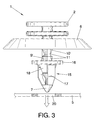
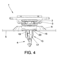
- the attachment device mainly stands out in that the lower elongated sector (4) is inserted in a retention bushing (15) that is coupled at a lower position, corresponding to the transport and supply position of the attachment device for the later insertion of the bushing (15) and the body (1) through the orifice (20), see figure 3, and is coupled at an upper retention position corresponding to the subsequent situation, see figure 4, where the retention of the bushing (15) is established with respect to the support (5).
- the lower elongated segment (4) comprises an end conical segment (7) and at a higher level is provided with a lower segment (8), an intermediate segment (9) and an upper segment (10), the intermediate segment (9) and upper segment (10) having incuts limited by vertical side ribs (11).
- the retention bushing (15) comprises an annular head (16) from where extend inferiorly elongated legs (17) alternating with short legs (18), so that in the lower insertion position the elongated legs (17) are housed in the lower segment (8) of the body and the short legs (18) are housed in the intermediate segment (9), and in the upper retention position the elongated legs (17) are placed on the ribs (11), bending and expanding outward under the lower face of the support (5) to establish their retention, while the short legs (18) are housed in the upper segment (10).
- the incuts in the intermediate segment (9) and upper segment (10) are limited by upper conical walls (9', 10') and by lower conical walls (9", 10") with an opposite inclination, the lower conical wall (10") of the upper segment (10) facilitating the sliding of the short legs (18) from the upper position to the lower position of the retention bushing (15), and the lower conical wall (9") of the intermediate segment (9) facilitates the extraction of the bushing (15) from the body (1).
- the incut of the lower segment (8) is limited by an upper conical wall (12) that facilitates the sliding of the elongated legs (17) from the lower to the upper position of the bushing (15), a lower cylindrical core (13) and a vertical rib (14) that prevents the bushing (15) from turning in the lower position of the bushing (15), the elongated legs (17) being housed in this incut of the lower segment (8) in the lower position of the retention bushing (15), the elongated legs (17) show a slight inclination near their lower ends and are integrated on the upper face of the conical end segment (7) to prevent them from hitting the edge of the orifice (20) of the support (5) while they are introduced through it.
Landscapes
- Engineering & Computer Science (AREA)
- General Engineering & Computer Science (AREA)
- Mechanical Engineering (AREA)
- Insertion Pins And Rivets (AREA)
- Connection Of Plates (AREA)
- Dowels (AREA)
- Vehicle Interior And Exterior Ornaments, Soundproofing, And Insulation (AREA)
Applications Claiming Priority (2)
| Application Number | Priority Date | Filing Date | Title |
|---|---|---|---|
| ES200400153A ES2246681B1 (es) | 2004-01-26 | 2004-01-26 | Dispositivo de fijacion entre un panel y un soporte. |
| ES200400153 | 2004-01-26 |
Publications (2)
| Publication Number | Publication Date |
|---|---|
| EP1571354A2 true EP1571354A2 (de) | 2005-09-07 |
| EP1571354A3 EP1571354A3 (de) | 2006-12-27 |
Family
ID=34746256
Family Applications (1)
| Application Number | Title | Priority Date | Filing Date |
|---|---|---|---|
| EP05380007A Withdrawn EP1571354A3 (de) | 2004-01-26 | 2005-01-12 | Vorrichtung zur Befestigung eines Paneels an ein Auflager |
Country Status (6)
| Country | Link |
|---|---|
| US (1) | US7237995B2 (de) |
| EP (1) | EP1571354A3 (de) |
| JP (1) | JP2005207598A (de) |
| CN (1) | CN100417819C (de) |
| CA (1) | CA2494219C (de) |
| ES (1) | ES2246681B1 (de) |
Cited By (2)
| Publication number | Priority date | Publication date | Assignee | Title |
|---|---|---|---|---|
| WO2007069036A1 (en) * | 2005-12-15 | 2007-06-21 | Itw Automotive Products Gmbh & Co. Kg | A fastening device for the releasable fastening of a flat structural member to a support structure |
| CN103591092A (zh) * | 2012-08-17 | 2014-02-19 | Trw车辆电气与零件有限公司 | 紧固夹具 |
Families Citing this family (33)
| Publication number | Priority date | Publication date | Assignee | Title |
|---|---|---|---|---|
| ES2246681B1 (es) * | 2004-01-26 | 2007-03-16 | I.T.W. España, S.A. | Dispositivo de fijacion entre un panel y un soporte. |
| FR2898164B1 (fr) * | 2006-03-02 | 2008-05-30 | I T W De France Soc Par Action | Attache munie d'un pied d'encliquetage a enfoncer au travers du trou d'un panneau |
| JP4920292B2 (ja) * | 2006-04-19 | 2012-04-18 | 株式会社ニフコ | 物品取付具 |
| JP5214310B2 (ja) * | 2008-04-15 | 2013-06-19 | トヨタ車体株式会社 | デッキサイドトリムの取付構造 |
| DE202008006958U1 (de) * | 2008-05-23 | 2008-10-02 | Trw Automotive Electronics & Components Gmbh | Verbindungsbaugruppe zur Befestigung eines Anbauelements auf einem Träger |
| CN101875332B (zh) * | 2009-11-17 | 2012-12-05 | 浙江吉利汽车研究院有限公司 | 一种汽车后柱装饰板的固定装置 |
| US10315558B2 (en) | 2010-05-24 | 2019-06-11 | Burton Technologies, Llc | Locking position stud fastener for a vehicle lamp assembly |
| US9610661B2 (en) * | 2010-05-24 | 2017-04-04 | Burton Technologies, Llc | Fastener for a vehicle lamp assembly |
| EP2577073B1 (de) | 2010-05-24 | 2020-07-29 | Burton Technologies, LLC | Befestigung für eine fahrzeuglampenanordnung |
| USD654354S1 (en) * | 2010-09-16 | 2012-02-21 | Byung-Kyu Jeon | Bolt for rivet |
| DE102011106310B4 (de) * | 2011-07-01 | 2013-01-31 | Trw Automotive Electronics & Components Gmbh | Befestigungsclip |
| US20130269158A1 (en) * | 2012-04-12 | 2013-10-17 | Microelectronics Technology, Inc. | Positioning pole and a positioning system and a method of positioning a pole to a covering |
| WO2015126565A1 (en) * | 2014-02-20 | 2015-08-27 | Illinois Tool Works Inc. | Fastener mounting assembly |
| US9528540B2 (en) | 2014-08-12 | 2016-12-27 | Newfrey Llc | Insertion-locking pin and grommet and related methods |
| JP6396277B2 (ja) * | 2015-11-26 | 2018-09-26 | 株式会社ニフコ | クリップ |
| US9873388B2 (en) * | 2016-04-06 | 2018-01-23 | Newfrey Llc | Automotive door trim fastener and molding method |
| CN106594029A (zh) * | 2016-12-30 | 2017-04-26 | 上汽通用五菱汽车股份有限公司 | 一种安装牢固、提升密封性的卡扣结构 |
| CN110337546B (zh) * | 2017-02-28 | 2022-02-22 | 伊利诺斯工具制品有限公司 | 紧固组件的夹持套筒装置 |
| DE102017118893A1 (de) * | 2017-08-18 | 2019-02-21 | Man Truck & Bus Ag | Halterung, insbesondere für eine Anzeigevorrichtung eines Kraftfahrzeug |
| JP6850773B2 (ja) * | 2018-08-22 | 2021-03-31 | 株式会社ニフコ | クリップ |
| FR3087507B1 (fr) * | 2018-10-23 | 2021-01-08 | Renault Sas | Dispositif de realignement vertical |
| US10900513B2 (en) | 2019-04-02 | 2021-01-26 | Newfrey Llc | Re-usable one-push pin and grommet fastener |
| DE102019111078A1 (de) | 2019-04-29 | 2020-10-29 | Böllhoff Verbindungstechnik GmbH | Befestigungsanordnung mit Dämpfungswirkung und Bauteilverbindung mit der Befestigungsanordnung |
| FR3095844B1 (fr) * | 2019-05-07 | 2021-04-16 | A Raymond Et Cie | Dispositif de fixation d’une première pièce à une seconde pièce |
| CN112081807A (zh) * | 2019-06-14 | 2020-12-15 | 伊利诺斯工具制品有限公司 | 紧固件 |
| EP4012199A4 (de) * | 2019-09-12 | 2023-10-18 | Nifco Inc. | Klammer und klammermontagestruktur |
| US11644052B2 (en) * | 2019-12-18 | 2023-05-09 | Illinois Tool Works Inc. | W-base fastener and locator cap |
| CN115151156B (zh) * | 2020-02-12 | 2025-06-06 | 米帕斯公司 | 头盔 |
| DE102020209264A1 (de) * | 2020-07-22 | 2022-01-27 | Volkswagen Aktiengesellschaft | Befestigungsanordnung, Kraftfahrzeug |
| CN112065917B (zh) * | 2020-08-20 | 2022-05-06 | 宁波甜宝生物信息技术有限公司 | 一种汽车零部件用减震机构及其使用方法 |
| CN112436328B (zh) * | 2020-11-13 | 2021-12-10 | 深圳市锦凌电子有限公司 | 一种具备快速拆卸卡设结构的连接器组件 |
| DE112022000795T5 (de) * | 2021-01-27 | 2023-11-16 | Illinois Tool Works Inc. | Anordnung zum bereitstellen einer befestigungsmöglichkeit für eine fahrzeugkomponente |
| DE102022118397A1 (de) * | 2022-07-22 | 2024-01-25 | Illinois Tool Works Inc. | Anordnung zum bereitstellen einer befestigungsmöglichkeit für eine fahrzeugkomponente |
Family Cites Families (31)
| Publication number | Priority date | Publication date | Assignee | Title |
|---|---|---|---|---|
| FR2214348A5 (de) * | 1973-01-12 | 1974-08-09 | Itw De France | |
| JPH0192508U (de) * | 1987-12-14 | 1989-06-16 | ||
| JPH0247414U (de) * | 1988-09-29 | 1990-03-30 | ||
| US4925351A (en) * | 1989-03-21 | 1990-05-15 | Trw, Inc. | Push-in fastener clip |
| JPH0323215U (de) * | 1989-07-18 | 1991-03-11 | ||
| AU626479B2 (en) * | 1989-12-12 | 1992-07-30 | W.A. Deutsher Pty Ltd | Two part fastener |
| US5201623A (en) * | 1992-02-18 | 1993-04-13 | Emhart Inc. | Two stage rivet |
| JP2585443Y2 (ja) * | 1992-03-30 | 1998-11-18 | 鬼怒川ゴム工業株式会社 | 留め具 |
| JP2582404Y2 (ja) * | 1992-05-26 | 1998-10-08 | 株式会社ニフコ | クリップ |
| JPH0640428U (ja) * | 1992-10-29 | 1994-05-31 | 株式会社ニフコ | プッシュリベット |
| JP2586907Y2 (ja) * | 1992-11-19 | 1998-12-14 | 株式会社ニフコ | 結合クリップ |
| DE19504692A1 (de) * | 1995-02-13 | 1996-08-14 | United Carr Gmbh Trw | Verbindung zwischen einem Träger und einem Plattenelement |
| US5647713A (en) * | 1996-05-22 | 1997-07-15 | Trw Inc. | Plastic panel fastener and method of forming the same |
| JPH10252726A (ja) * | 1997-03-12 | 1998-09-22 | Nifco Inc | クリップ |
| DE29718487U1 (de) * | 1997-10-17 | 1997-12-18 | Trw United-Carr Gmbh & Co Kg, 67677 Enkenbach-Alsenborn | Verbindung zwischen einem Träger, insbesondere einem Karosserieteil eines Kraftfahrzeugs, und einem Plattenelement |
| DE19753678A1 (de) * | 1997-12-03 | 1999-06-10 | United Carr Gmbh Trw | Verbindung zwischen einem Träger, insbesondere einem Karosserieteil eines Kraftfahrzeuges, und einem Plattenelement, insbesondere einer Türverkleidung |
| FR2776345B1 (fr) * | 1998-03-17 | 2000-06-30 | Itw De France | Dispositif a monter en aveugle |
| DE29810437U1 (de) * | 1998-06-10 | 1998-10-01 | TRW Automotive Electronics & Components GmbH & Co. KG, 78315 Radolfzell | Verbindungselement zwischen einem Träger, insbesondere einem Karosserieteil eines Kraftfahrzeuges und einem Plattenelement |
| JP4488588B2 (ja) * | 2000-05-29 | 2010-06-23 | 株式会社ニフコ | クリップ |
| JP2002081423A (ja) * | 2000-09-07 | 2002-03-22 | Nippon Pop Rivets & Fasteners Ltd | クリップ |
| AU2000276652A1 (en) | 2000-10-03 | 2002-04-15 | I.T.W. Espana S.A. | Device for fixing together a panel and a support plate |
| US6431585B1 (en) * | 2000-10-05 | 2002-08-13 | Lear Corporation | Dual stage fastener |
| ES2233707T3 (es) * | 2000-10-10 | 2005-06-16 | TRW AUTOMOTIVE ELECTRONICS & COMPONENTS GMBH & CO. KG | Dispositivo para unir un soporte, en particular una parte de carroceria de un vehiculo automovil, con un elemento de placa, en particular un revestimiento de puerta o pared. |
| DE20017376U1 (de) * | 2000-10-10 | 2001-02-15 | TRW Automotive Electronics & Components GmbH & Co. KG, 78315 Radolfzell | Vorrichtung zur Verbindung eines Trägers, insbesondere eines Karosserieteils eines Kraftfahrzeuges, mit einem Plattenelement, insbesondere einer Tür- oder Wandverkleidung |
| US6533515B2 (en) * | 2001-07-17 | 2003-03-18 | Illinois Tool Works | Fastener having movable drive pin |
| DE60319680D1 (de) | 2002-01-29 | 2008-04-24 | Newfrey Llc | Klammer |
| JP2003222113A (ja) * | 2002-01-29 | 2003-08-08 | Nippon Pop Rivets & Fasteners Ltd | クリップ |
| US6813865B2 (en) * | 2002-06-12 | 2004-11-09 | Lear Corporation | Fastener assembly for use with a trim panel |
| JP2004116722A (ja) * | 2002-09-27 | 2004-04-15 | Nippon Pop Rivets & Fasteners Ltd | クリップ |
| ES2246681B1 (es) * | 2004-01-26 | 2007-03-16 | I.T.W. España, S.A. | Dispositivo de fijacion entre un panel y un soporte. |
| ES2246118B1 (es) * | 2004-01-26 | 2007-03-16 | I.T.W. España, S.A. | Pieza de union entre un panel y un soporte. |
-
2004
- 2004-01-26 ES ES200400153A patent/ES2246681B1/es not_active Expired - Fee Related
-
2005
- 2005-01-12 EP EP05380007A patent/EP1571354A3/de not_active Withdrawn
- 2005-01-19 US US11/037,020 patent/US7237995B2/en not_active Expired - Fee Related
- 2005-01-21 JP JP2005014311A patent/JP2005207598A/ja active Pending
- 2005-01-25 CN CNB2005100028205A patent/CN100417819C/zh not_active Expired - Fee Related
- 2005-01-25 CA CA002494219A patent/CA2494219C/en not_active Expired - Fee Related
Cited By (3)
| Publication number | Priority date | Publication date | Assignee | Title |
|---|---|---|---|---|
| WO2007069036A1 (en) * | 2005-12-15 | 2007-06-21 | Itw Automotive Products Gmbh & Co. Kg | A fastening device for the releasable fastening of a flat structural member to a support structure |
| CN103591092A (zh) * | 2012-08-17 | 2014-02-19 | Trw车辆电气与零件有限公司 | 紧固夹具 |
| CN103591092B (zh) * | 2012-08-17 | 2017-12-15 | 伊利诺斯工具制品有限公司 | 紧固夹具 |
Also Published As
| Publication number | Publication date |
|---|---|
| US7237995B2 (en) | 2007-07-03 |
| CN100417819C (zh) | 2008-09-10 |
| JP2005207598A (ja) | 2005-08-04 |
| US20050163587A1 (en) | 2005-07-28 |
| ES2246681B1 (es) | 2007-03-16 |
| CA2494219C (en) | 2008-04-01 |
| EP1571354A3 (de) | 2006-12-27 |
| ES2246681A1 (es) | 2006-02-16 |
| CN1680729A (zh) | 2005-10-12 |
| CA2494219A1 (en) | 2005-07-26 |
Similar Documents
| Publication | Publication Date | Title |
|---|---|---|
| US20050163587A1 (en) | Device for attaching a panel to a support | |
| US8240716B2 (en) | Quick connector coupling with pull tab verifier | |
| US20060103134A1 (en) | Passive transmitter for a quick connector | |
| US6676171B2 (en) | Insertion verifier dust cap | |
| US7484774B2 (en) | Redundant latch/verifier for a quick connector | |
| US7207759B2 (en) | Fastener for panels or the like | |
| CN104603477B (zh) | 紧固夹组件 | |
| CN102753877A (zh) | 具有轮廓导入部分的流体连接器闩 | |
| US9249818B2 (en) | Shelving connector and method of manufacture | |
| US20050191119A1 (en) | Universal joint component and automotive lamp unit | |
| EP1734299A3 (de) | Ziehlaschenanordnung zum Anzeigen der korrekten Verbindung für Schnellkupplungen | |
| KR20070100656A (ko) | 혼합식 급속 커넥터 | |
| JPH08270861A (ja) | クイック・コネクター継手 | |
| CN112654790B (zh) | 紧固夹组件 | |
| US20090020061A1 (en) | Connector for Releasable Connection Between an Achorage in the Form of a Female Part Arranged on a Floating Means and a Male Part Formed at the End of a Retrievable Umbilical | |
| CN1214763A (zh) | 快速连接管接头的连接检验装置 | |
| WO2004061240A8 (en) | Road mats | |
| CA2200987A1 (en) | Re-usable breakaway safety joint | |
| EP1719944B1 (de) | Schnellkupplung | |
| US20080235862A1 (en) | Multi-Purpose Beading For Swimming Pool Liners | |
| US9845062B2 (en) | Universal sewer inlet fitting | |
| CN217653483U (zh) | 一种管材卡扣 | |
| JP2002542108A (ja) | 結合式の車両本体搭載物 | |
| JP4023756B2 (ja) | 仮設足場用連結金具におけるクサビの取付け方法 | |
| JP3790584B2 (ja) | 無目と方立との結合装置及び結合方法 |
Legal Events
| Date | Code | Title | Description |
|---|---|---|---|
| PUAI | Public reference made under article 153(3) epc to a published international application that has entered the european phase |
Free format text: ORIGINAL CODE: 0009012 |
|
| AK | Designated contracting states |
Kind code of ref document: A2 Designated state(s): AT BE BG CH CY CZ DE DK EE ES FI FR GB GR HU IE IS IT LI LT LU MC NL PL PT RO SE SI SK TR |
|
| AX | Request for extension of the european patent |
Extension state: AL BA HR LV MK YU |
|
| PUAL | Search report despatched |
Free format text: ORIGINAL CODE: 0009013 |
|
| AK | Designated contracting states |
Kind code of ref document: A3 Designated state(s): AT BE BG CH CY CZ DE DK EE ES FI FR GB GR HU IE IS IT LI LT LU MC NL PL PT RO SE SI SK TR |
|
| AX | Request for extension of the european patent |
Extension state: AL BA HR LV MK YU |
|
| RIC1 | Information provided on ipc code assigned before grant |
Ipc: F16B 21/09 20060101ALI20061123BHEP Ipc: B60R 13/02 20060101ALI20061123BHEP Ipc: F16B 5/06 20060101AFI20050706BHEP |
|
| 17P | Request for examination filed |
Effective date: 20070124 |
|
| AKX | Designation fees paid |
Designated state(s): DE ES FR IT |
|
| STAA | Information on the status of an ep patent application or granted ep patent |
Free format text: STATUS: THE APPLICATION IS DEEMED TO BE WITHDRAWN |
|
| 18D | Application deemed to be withdrawn |
Effective date: 20100803 |