EP1573073B1 - Gefäss für die metallurgische behandlung von roheisen, stahlschmelzen u.dgl., insbesondere konvertergefäss - Google Patents
Gefäss für die metallurgische behandlung von roheisen, stahlschmelzen u.dgl., insbesondere konvertergefäss Download PDFInfo
- Publication number
- EP1573073B1 EP1573073B1 EP03753470A EP03753470A EP1573073B1 EP 1573073 B1 EP1573073 B1 EP 1573073B1 EP 03753470 A EP03753470 A EP 03753470A EP 03753470 A EP03753470 A EP 03753470A EP 1573073 B1 EP1573073 B1 EP 1573073B1
- Authority
- EP
- European Patent Office
- Prior art keywords
- vessel
- support ring
- bracket
- lever
- clamping
- Prior art date
- Legal status (The legal status is an assumption and is not a legal conclusion. Google has not performed a legal analysis and makes no representation as to the accuracy of the status listed.)
- Expired - Lifetime
Links
Images


Classifications
-
- C—CHEMISTRY; METALLURGY
- C21—METALLURGY OF IRON
- C21C—PROCESSING OF PIG-IRON, e.g. REFINING, MANUFACTURE OF WROUGHT-IRON OR STEEL; TREATMENT IN MOLTEN STATE OF FERROUS ALLOYS
- C21C5/00—Manufacture of carbon-steel, e.g. plain mild steel, medium carbon steel or cast steel or stainless steel
- C21C5/28—Manufacture of steel in the converter
- C21C5/42—Constructional features of converters
- C21C5/46—Details or accessories
- C21C5/4633—Supporting means
-
- C—CHEMISTRY; METALLURGY
- C21—METALLURGY OF IRON
- C21C—PROCESSING OF PIG-IRON, e.g. REFINING, MANUFACTURE OF WROUGHT-IRON OR STEEL; TREATMENT IN MOLTEN STATE OF FERROUS ALLOYS
- C21C5/00—Manufacture of carbon-steel, e.g. plain mild steel, medium carbon steel or cast steel or stainless steel
- C21C5/28—Manufacture of steel in the converter
- C21C5/42—Constructional features of converters
- C21C5/46—Details or accessories
Definitions
- the invention relates to a vessel for the metallurgical treatment of pig iron, steel melts u.
- a converter vessel which is supported on a spaced-apart support ring which is tiltable by means of tilting pin in both sides Kipplagem, over the circumference of the vessel wall distributed claws rest on the upper flange of the support ring and wherein the support on the upper flange of the support ring means additional fastening means is detachably formed.
- claws fasteners such as. Clamping screws, hinged screws and pincer mechanisms with appropriate operation, all of which have the stated disadvantages and are very difficult to handle and their handling takes too much time. Due to the operational heating of the vessels also occur thermal expansions in the individual components that complicate the release of the fasteners. In addition, there is also the fact that the release and change process must be carried out at the increased ambient temperatures by the operator from close range. In the relatively tight accessibility loosening of clamping nuts with appropriate tool is quite power consuming.
- the invention has for its object to provide a fast, easy and manageable at a sufficient distance means that does not have the disadvantages mentioned.
- the support on the upper flange of the support ring consists of each opposite vessel brackets and support ring brackets, which by means of a snap closure in a closed direction to a secure closed position with each other braced and easily detachable in an opposite direction of actuation are.
- an actuating element In the closed state, an actuating element is moved beyond the so-called dead center and can be brought into a self-locking and lock-secure position.
- the distributed on the circumference brackets can be arranged symmetrically or asymmetrically depending on Tragringform and serve as points of attack for such a quick-fastening device.
- the resulting lever system is adapted to the clamping distances and ensures the secure hold of the vessel even in tilting positions.
- the snap closure can also be easily and safely pressed into the closed position or the release position with a manually attached hydraulic handling device. Consequently, the same auxiliary device can be used for opening. It is first moved out of the dead center until the open position is reached.
- the snap closure consists of a vessel console encompassing clamping bracket which is pivotally mounted on an actuating lever, wherein the actuating lever with its upper End is pivotally mounted rotatably on the support ring console.
- This design is further developed so that in the closing direction of the clamping bracket surrounds the vessel console and rests against the outer peripheral surface of the support ring and that the actuating lever is latched with locking bolts, which are arranged on both sides of the clamping bracket.
- the pushing back of the actuating lever to the support ring causes a pivoting away from the support ring and releases the vessel console for removal of the vessel.
- Such an actuating mechanism saves the usual underlay elements with a spherical seat and the corresponding handling of the components. For the operator, only a small amount of force and relatively short time access to the quick-change attachment system is required.
- the release of the vessel can be achieved in a simple manner, that during an opening movement of the actuating lever from the peripheral surface of the support ring to the outside of the clamping bracket on the vessel console is pivotable into an open position.
- the arrangement is made such that the vessel console in the side profile forms a lower recess in which the support ring console with clear space fits. This consumes very little space.
- the number of vessel brackets and support ring brackets may vary depending on the shape of the support ring (whether full or partial ring).
- the flap closure can be arranged on the top flange, outside or at a distance between the support ring and the vessel.
- a second alternative embodiment is that the vessel console consists of a single, correspondingly thick sized console plate.
- the support ring console consists of a single, appropriately sized console plate.
- the associated lever systems are designed according to a development in such a way that the clamping bracket consists of two spaced, parallel clamping straps which are connected at their ends by means of a transverse, spacer element, or are rotatably connected to spaced support ring-Konsolplatten, wherein in a central , thick support ring console, the spacer element lever tabs for the actuating lever receives and forms the pivot bearing.
- the actuating lever consists of two spaced, parallel lever tabs which, forming the pivot bearing, are connected by means of transverse spacer elements.
- a clamping element is formed of a running between the spaced, parallel vessel brackets or between spaced support ring console plates tension lever rod with a resting on this hammer head, which is connected to the, connecting the two lever brackets pivot bearing and between two support ring console plates runs.
- the vessel console encompasses an oval, closed clamping bracket forms.
- a vessel 1 which, for example, consists of a converter vessel 1a, is used for the metallurgical treatment of melts, for example the refining of pig iron or steel melts.
- the vessel 1 is supported at a distance 2 on a support ring 3 by means of over the circumference of the vessel wall 1 b distributed claws 6 and between these or these associated supports 4.
- These supports 4 consist of additional fasteners.
- the claws 6 lie, open at the top, laterally between guide walls 5 a, which respectively constitute vessel guides 5.
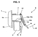
- Each support 4 consists (Fig. 1) on the upper flange 3a of the support ring 3 each of an opposing vessel console 7 and a support ring console 8, by means of a closer to be described snap closure 9 in a closing direction 10 to a secure closed position 11 are clamped together and easily detachable in an opposite direction of actuation 12.
- the clamping bracket 13 moves during the opening movement in the opposite direction of actuation 12 and back to the closed position 11 on the vessel console 7 away, with the actuating lever 14 only from the outer peripheral surface 3 c of the support ring 3 away ( Fig. 3) and then this again approaches (Fig. 4). As a result, the open position 16 is reached.
- the vessel console 7 forms a lower recess 7b in the side profile 7a, in which the support ring console 8 with space between them finds space.
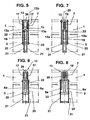
- FIGS. 5 to 8 various alternatives for the vessel console 7, the support ring console 8 and the clamping bracket 13 are shown.
- the vessel console 7 consists of two console plates 17 arranged laterally at a fixed distance 7c.
- the vessel console 7 consists of a single, correspondingly thickly dimensioned console plate 18.
- the support ring console 8 is made analogous to a single, correspondingly thick sized console plate 19.
- the tensioning bow 13 (FIGS. 5 and 7) is formed from two spaced, parallel tensioning straps 13a and 13, which are connected at their ends 13b by means of a transverse spacer element 20.
- a pivot bearing 22 may be provided for rotation of the tension bracket 13 relative to the actuating lever 14.
- the lever tabs 21 receives for the actuating lever 14, provided for a pivot bearing 22.
- the actuating lever 14 is formed in each case from two spaced, parallel lever tabs 21 which receive the pivot bearing 22 and the lever tabs 21 are connected by means of the transverse spacer elements 20.
- FIGS. 6 and 7 Other alternative embodiments include FIGS. 6 and 7 with respect to the embodiment of the tension bow 13.
- a tension bow 13 is in the form of a tensioning element 23 of a between the spaced, parallel vessel brackets 7 or between spaced support ring console plates 8a extending clamping lever rod 24 formed with a resting on this hammer head 25.
- the tension lever rod 24 is itself connected to the pivot bearing 22 connecting the two lever tabs 21 and extends between two support ring console plates 8a.
- the tension lever rod 24 extends between two support ring console plates 8a and forms a vessel console 7 embracing, oval shaped, closed clamping bracket 26th
Landscapes
- Chemical & Material Sciences (AREA)
- Engineering & Computer Science (AREA)
- Manufacturing & Machinery (AREA)
- Materials Engineering (AREA)
- Metallurgy (AREA)
- Organic Chemistry (AREA)
- Carbon Steel Or Casting Steel Manufacturing (AREA)
- Clamps And Clips (AREA)
- Pressure Vessels And Lids Thereof (AREA)
- Refinement Of Pig-Iron, Manufacture Of Cast Iron, And Steel Manufacture Other Than In Revolving Furnaces (AREA)
- Vehicle Step Arrangements And Article Storage (AREA)
- Accessories For Mixers (AREA)
- Sampling And Sample Adjustment (AREA)
Description
- Die Erfindung betrifft ein Gefäß für die metallurgische Behandlung von Roheisen, Stählschmelzen u. dgl., insbesondere ein Konvertergefäß, das sich auf einen mit Abstand angeordneten Tragring abstützt, der mittels Kippzapfen in beidseitigen Kipplagem kippbar ist, wobei über den Umfang der Gefäßwandung verteilte Pratzen auf dem Obergurt des Tragrings aufliegen und wobei die Abstützung auf dem Obergurt des Tragrings mittels zusätzlichen Befestigungsmitteln lösbar ausgebildet ist.
- Die Aufgabe, ein Konvertergefäß etwa der vorstehenden Gestaltung zu schaffen, dessen Einzelteile mit einfachen Mitteln auswechselbar sind und dazu die Verbindung zwischen den Gefäß-Pratzen und dem Tragring sowie zwischen Führungsstücken und zusätzlichen Befestigungselementen lösbar zu machen, ist bekannt (DE 199 28 195 A1). Dazu fehlt es jedoch an geeigneten Mitteln, unter den Bedingungen eines heißen Konvertergefäßes dieses Lösen und Wiederbefestigen eines zu wechselnden Gefäßes durchzuführen.
- in der Praxis erfordern metallurgische Behandlungsgefäße aufgrund des relativ hohen Ausmauerungs-Verschleißes einen schnellen Austausch, um die Produktiensausfallzeit gering zu halten.
- Die Grundlage bilden bisher zu den in oben offenen Führungen liegenden Pratzen hinzukommende Befestigungselemente, wie bspw. Klemmschrauben, klappbare Schrauben sowie Zangenmechanismen mit entsprechender Betätigung, die alle die angegebenen Nachteile aufweisen und nur sehr schwierig handhabbar sind und deren Handhabung zuviel Zeit in Anspruch nimmt. Aufgrund der betriebsbedingten Erwärmung der Gefäße treten außerdem Wärmedehnungen in den einzelnen Bauteilen auf, die das Lösen der Befestigungselemente erschweren. Darüber hinaus kommt noch hinzu, dass der Löse- und Wechselvorgang bei den erhöhten Umgebungstemperaturen durch das Bedienungspersonal aus nächster Nähe durchgeführt werden muss. Bei der relativ beengten Zugänglichkeit ist ein Lösen von Spannmuttern mit entsprechendem Werkzeug ziemlich kraftaufwändig.
- Der Erfindung liegt die Aufgabe zugrunde, ein schnell, leicht und im ausreichenden Abstand handhabbares Mittel vorzuschlagen, das die genannten Nachteile nicht aufweist.
- Die gestellte Aufgabe wird erfindungsgemäß dadurch gelöst, dass die Abstützung auf dem Obergurt des Tragrings aus jeweils sich gegenüberliegenden Gefäß-Konsolen und Tragring-Konsolen besteht, die mittels eines Klappverschlusses in einer Schließrichtung bis in eine gesicherte Schließstellung miteinander verspannbar und in einer entgegengesetzten Betätigungsrichtung leicht lösbar sind. Im Schließzustand wird ein Betätigungselement über den sog. Totpunkt hinweg bewegt und kann in eine selbsthemmende und verriegelungssichere Lage gebracht werden. Die am Umfang verteilten Konsolen können je nach Tragringform symmetrisch oder asymmetrisch angeordnet sein und dienen als Angriffsstellen für eine solche Schnell-Befestigungseinrichtung. Das sich ergebende Hebelsystem ist auf die Klemmabstände abgestimmt und gewährleistet den sicheren Halt des Gefäßes auch in Kipppositionen. Der Klappverschluss kann weiterhin mit einem manuell anzubringenden hydraulischen Handhabungsgerät leicht und sicher in die Schließstellung oder die LöseStellung gedrückt werden. Zum Öffnen kann demzufolge dasselbe Hilfsgerät angesetzt werden. Dabei wird zuerst aus der Totpunktlage herausgefahren, bis die Offenstellung erreicht ist.
- Im einzelnen ist vorgesehen, dass der Klappverschluss aus einem die Gefäß-Konsole umgreifenden Spannbügel besteht, der schwenkbar an einem Betätigungshebel drehgelagert ist, wobei der Betätigungshebel mit seinem oberen Ende schwenkbar an der Tragring-Konsole drehgelagert ist. Dadurch entsteht auch nur ein geringer Aufwand pro Befestigungsstelle.
- Diese Gestaltung ist dahingehend weiterentwickelt, dass in Schließrichtung der Spannbügel die Gefäß-Konsole umgreift und an der äußeren Umfangsfläche des Tragrings anliegt und dass der Betätigungshebel mit Verriegelungsbolzen verrastet ist, die beidseitig am Spannbügel angeordnet sind. Das Zurückdrücken des Betätigungshebels an den Tragring bewirkt ein Wegschwenken vom Tragring und gibt die Gefäß-Konsole zum Ausbau des Gefäßes frei. Ein solcher Betätigungsmechanismus spart die sonst üblichen Unterlegelemente mit sphärischem Sitz und das entsprechende Hantieren mit den Bauteilen. Für das Bedienungspersonal ist nur ein geringer Kraftaufwand und ein zeitlich relativ kurzer Zugang zum Schnellwechsel-Befestigungssystem erforderlich.
- Die Freigabe des Gefäßes kann auf einfache Weise dadurch erzielt werden, dass während einer Öffnungsbewegung des Betätigungshebels von der Umfangsfläche des Tragrings nach außen der Spannbügel über die Gefäß-Konsole bis in eine Offenstellung schwenkbar ist.
- Die Anordnung ist dabei derart getroffen, dass die Gefäß-Konsole im Seitenprofil eine untere Ausnehmung bildet, in der die Tragring-Konsole mit lichtem Abstand Platz findet. Dadurch wird sehr wenig Raum verbraucht.
- Die Anzahl von Gefäß-Konsolen und Tragring-Konsolen kann sich nach der Form des Tragrings ( ob Vollring oder Teil-Ring) richten. Außerdem kann der Klappverschluss auf dem Obergurt, außen oder im Abstand zwischen Tragring und Gefäß angeordnet sein.
- Alternativen für die Ausführung ergeben sich zunächst dadurch, dass die Gefäß-Konsole aus zwei seitlich mit fest bestimmtem Abstand angeordneten Konsolplatten besteht.
- Eine zweite alternative Ausführungsform besteht darin, dass die Gefäß-Konsole aus einer einzelnen, entsprechend dick bemessenen Konsolplatte besteht.
- Analog zu diesen beiden Gestaltungen besteht die Tragring-Konsole aus einer einzigen, entsprechend bemessenen Konsolplatte.
- Die zugehörigen Hebel-Systeme sind nach einer Weiterbildung derart gestaltet, dass der Spannbügel aus zwei beabstandeten, parallelen Spannlaschen besteht, die an ihren Enden mittels eines quer verlaufenden, Distanzelementes verbunden sind, oder mit beabstandeten Tragring-Konsolplatten drehbar verbunden sind, wobei in einer mittigen, dicken Tragring-Konsole das Distanzelement Hebellaschen für den Betätigungshebel aufnimmt und dessen Drehlagerung bildet. Daraus ergeben sich nicht nur mehrere alternative Bauweisen, sondern auch eine wirtschaftliche Herstellung der Bauteile.
- Analog zur Gestaltung des Spannbügels besteht der Betätigungshebel aus zwei beabstandeten, parallelen Hebellaschen, die, die Drehlagerung bildend, mittels quer verlaufenden Distanzelementen verbunden sind.
- Eine andere Ausführungsform sieht vor, dass ein Spannelement aus einer zwischen den beabstandeten, parallelen Gefäß-Konsolen bzw. zwischen beabstandeten Tragring-Konsolplatten verlaufenden Spannhebelstange mit einem auf diesen aufliegenden Hammerkopf gebildet ist, die an die, die beiden Hebellaschen verbindende Drehlagerung angeschlossen ist und zwischen zwei Tragring-Konsolplatten verläuft.
- Nach anderen Merkmalen ist vorgesehen, dass die Spannhebelstange, zwischen zwei Tragring-Konsolplatten verlaufend, die Gefäß-Konsole umgreifend einen ovalen, geschlossenen Spannbügel bildet.
- In der Zeichnung sind Ausführungsbeispiele der Erfindung dargestellt, die nachstehend näher erläutert werden.
- Es zeigen:
- Fig. 1
- einen Ausschnitt eines Gefäßes mit Gefäß-Konsole und Tragring-Konsole und Klappverschluss in Seitenansicht,
- Fig. 2
- eine ausschnittsweise Draufsicht auf die beidseitig zu einer Pratze angeordneten Führungswände,
- Fig. 3
- die Seitenansicht wie Fig. 1 mit dem Klappverschluss in Offenstellung,
- Fig. 4
- die Seitenansicht wie in Fig. 1 mit dem Klappverschluss in einer gesicherten Offenstellung,
- Fig. 5
- eine Vorderansicht auf Gefäß und Tragring jeweils ausschnittsweise, mit paarweisen Gefäß-Konsolplatten und einer einzigen Tragring-Konsolplatte,
- Fig. 6
- dieselbe Vorderansicht auf Gefäß und Tragring jeweils ausschnittsweise auf paarweise Gefäß-Konsolplatten und Tragring-Konsolplatten,
- Fig. 7
- dieselbe Vorderansicht mit einer einzigen Gefäß-Konsolplatte und einer einzigen Tragring-Konsolplatte und
- Fig. 8
- eine Vorderansicht mit einer einzigen Gefäß-Konsolplatte und paarweisen Tragring-Konsolplatten.
- Ein Gefäß 1, das bspw. aus einem Konvertergefäß 1a besteht, dient der metallurgischen Behandlung von Schmelzen, bspw. dem Frischen von Roheisen oder von Stahlschmelzen. Das Gefäß 1 stützt sich mit einem Abstand 2 auf einen Tragring 3 und zwar durch über den Umfang an der Gefäßwandung 1 b verteilte Pratzen 6 und zwischen diesen oder diesen zugeordnete Abstützungen 4. Diese Abstützungen 4 bestehen aus zusätzlichen Befestigungselementen. Der Tragring 3, der einen Obergurt 3a und einen Untergurt 3b bildet, stützt die Pratzen 6 des Gefäßes 1. Die Pratzen 6 liegen, nach oben offen, seitlich zwischen Führungswänden 5a, die jeweils Gefäßführungen 5 bilden.
- Zwischen zwei jeweils benachbarten Pratzen 6 sind die zusätzlichen Befestigungselemente vorgesehen. Dort befinden sich an der Gefäßwandung 1 b mehrere, entsprechend über den Umfang verteilte Gefäß-Konsolen 7. Auf einem Obergurt 3a des Tragrings 3 sind analoge Tragring-Konsolen 8 befestigt.
- Jede Abstützung 4 besteht (Fig. 1) auf dem Obergurt 3a des Tragrings 3 aus jeweils sich einer gegenüberliegenden Gefäß-Konsole 7 und einer Tragring-Konsole 8, die mittels eines noch näher zu beschreibenden Klappverschlusses 9 in einer Schließrichtung 10 bis in eine gesicherte Schließstellung 11 miteinander verspannbar und in einer entgegengesetzten Betätigungsrichtung 12 leicht lösbar sind.
- Dabei besteht der Klappverschluss 9 ( Fig. 3, die das Öffnen auf etwa halbem Weg zeigt ) aus einem die Gefäß-Konsole 7 umgreifenden Spannbügel 13, der schwenkbar an einem Betätigungshebel 14 drehgelagert ist, wobei der Betätigungshebel 14 mit seinem oberen Ende 14a schwenkbar an der Tragring-Konsole 8 drehgelagert ist. In Schließstellung 11 umgreift der Spannbügel 13 die Gefäß-Konsole 7 und liegt (Fig. 1) an der äußeren Umfangsfläche 3c des Tragrings 3 an und ist mittels Verriegelungsbolzen 15 verrastet, die beidseitig am Spannbügel 13 in Spannlaschen 13a, 13a eingebaut sind.
- Gemäß den Fig. 3 und 4 bewegt sich der Spannbügel 13 während der Öffnungsbewegung in der entgegengesetzten Betätigungsrichtung 12 und zurück in die Schließstellung 11 über die Gefäß-Konsole 7 hinweg, wobei sich der Betätigungshebel 14 erst von der äußeren Umfangsfläche 3c des Tragrings 3 entfernt ( Fig. 3) und sich dann dieser wieder annähert ( Fig. 4). Dadurch ist die Offenstellung 16 erreicht.
- Für eine kompakte Anordnung und möglichst kleine Hebelwege bildet die Gefäß-Konsole 7 im Seitenprofil 7a eine untere Ausnehmung 7b, in der die Tragring-Konsole 8 mit lichtem Abstand Platz findet.
- In den Fig. 5 bis 8 sind verschiedene Alternativen für die Gefäß-Konsole 7, die Tragring-Konsole 8 und den Spannbügel 13 dargestellt.
- Gemäß Fig. 5 besteht die Gefäß-Konsole 7 aus zwei seitlich mit fest bestimmtem Abstand 7c angeordnete Konsolplatten 17.
- Demgegenüber besteht gemäß Fig. 7 die Gefäß-Konsole 7 aus einer einzelnen, entsprechend dick bemessenen Konsolplatte 18.
- Gemäß Fig. 5 ist die Tragring-Konsole 8 analog dazu aus einer einzigen, entsprechend dick bemessenen Konsolplatte 19 hergestellt.
- Der Spannbügel 13 ( Fig. 5 und 7) ist aus zwei beabstandeten, parallelen Spannlaschen 13a und 13 gebildet, die an ihren Enden 13b mittels eines quer verlaufenden Distanzelementes 20 verbunden sind.
- In den Fig. 6 und 8 sind beabstandete Tragring-Konsolplatten 8a vorgesehen. In den Tragring-Konsolplatten 8a kann auch eine Drehlagerung 22 zur Drehung des Spannbügels 13 gegenüber dem Betätigungshebel 14 vorgesehen sein. In der mittigen, dicken Tragring-Konsolplatte 19 ist das Distanzelement 20, das Hebellaschen 21 für den Betätigungshebel 14 aufnimmt, für eine Drehlagerung 22 vorgesehen.
- Gemäß den Fig. 5, 6, 7 und 8 ist der Betätigungshebel 14 jeweils aus zwei beabstandeten, parallelen Hebellaschen 21 gebildet, die die Drehlagerung 22 aufnehmen und die Hebellaschen 21 sind mittels der quer verlaufenden Distanzelemente 20 verbunden.
- Weitere alternative Ausführungsformen enthalten die Fig. 6 und 7 bezüglich der Ausführungsform des Spannbügels 13. Ein Spannbügel 13 ist in Form eines Spannelementes 23 aus einer zwischen den beabstandeten, parallelen Gefäß-Konsolen 7 bzw. zwischen beabstandeten Tragring-Konsolplatten 8a verlaufenden Spannhebelstange 24 mit einem auf diesen aufliegenden Hammerkopf 25 gebildet. Die Spannhebelstange 24 ist selbst an die, die beiden Hebellaschen 21 verbindende Drehlagerung 22 angeschlossen und verläuft zwischen zwei Tragring-Konsolplatten 8a.
- Gemäß Fig. 8 verläuft die Spannhebelstange 24 zwischen zwei Tragring-Konsolplatten 8a und bildet einen die Gefäß-Konsole 7 umgreifenden, oval geformten, geschlossenen Spannbügel 26.
-
- 1
- Gefäß
- 1a
- Konvertergefäß
- 1b
- Gefäßwandung
- 2
- Abstand
- 3
- Tragring
- 3a
- Obergurt
- 3b
- Untergurt
- 3c
- äußere Umfangsfläche
- 4
- Abstützung
- 5
- Gefäßführung
- 5a
- Führungswand
- 5b
- Führungsstück
- 6
- Pratzen
- 7
- Gefäß-Konsole
- 7a
- Seitenprofil
- 7b
- untere Ausnehmung
- 7c
- Seitenabstand
- 8
- Tragring-Konsole
- 8a
- Tragring-Konsolplatte
- 9
- Klappverschluss
- 10
- Schließrichtung
- 11
- Schließstellung
- 12
- entgegengesetzte Betätigungsrichtung
- 13
- Spannbügel
- 13a
- Spannlaschen
- 13b
- Spannlaschen-Ende
- 14
- Betätigungshebel
- 14a
- oberes Ende
- 15
- Verriegelungsbolzen
- 16
- Offenstellung
- 17
- beabstandete Gefäß-Konsolplatten
- 18
- dicke, einzelne Gefäß-Konsolplatte
- 19
- dicke, einzelne Tragring-Konsolplatte
- 20
- Distanzelement
- 21
- Hebellaschen
- 22
- Drehlagerung
- 23
- Spannelement
- 24
- Spannhebelstange
- 25
- Hammerkopf
- 26
- geschlossener Spannbügel
Claims (12)
- Gefäß (1) für die metallurgische Behandlung von Roheisen, Stahlschmelzen u. dgl., insbesondere Konvertergefäß (1a), das sich auf einen mit Abstand (2) angeordneten Tragring (3) abstützt, der mittels Kippzapfen in beidseitigen Kipplagem kippbar ist, wobei über den Umfang der Gefäßwandung (1b) verteilte Pratzen (6) auf dem Obergurt (3a) des Tragrings (3) aufliegen und wobei eine Abstützung (4) auf dem Obergurt (3a) des Tragrings (3) mittels zusätzlichen Befestigungselementen lösbar ausgebildet ist,
dadurch gekennzeichnet,
dass die Abstützung (4) auf dem Obergurt (3a) des Tragrings (3) aus jeweils sich gegenüberliegenden Gefäß- Konsolen (7) und Tragring-Konsolen (8) besteht, die mittels eines Klappverschlusses (9) in einer Schließrichtung (10) bis in eine gesicherte Schließstellung (11) miteinander verspannbar und in einer entgegengesetzten Betätigungsrichtung (12) leicht lösbar sind. - Gefäß nach Anspruch 1,
dadurch gekennzeichnet,
dass der Klappverschluss (9) aus einem die Gefäß-Konsole (7) umgreifenden Spannbügel (13) besteht, der schwenkbar an einem Betätigungshebel (14) drehgelagert ist, wobei der Betätigungshebel (14) mit seinem oberen Ende (14a) schwenkbar an der Tragcing-Konsote (8) drehgelagert ist. - Gefäß nach einem der Ansprüche 1 oder 2,
dadurch gekennzeichnet,
dass in Schließrichtung (10) der Spannbügel (13) die Gefäß-Konsole (7) umgreift und an der äußeren Umfangsfläche (3c) des Tragrings (3) in Schließstellung (11) anliegt und dass der Betätigungshebel (14) mit Verriegelungsbolzen (15) verrastet ist, die beidseitig am Spannbügel (13) ange-ordnet sind. - Gefäß nach einem der Ansprüche 1 bis 3,
dadurch gekennzeichnet,
dass während einer Öffnungsbewegung des Betätigungshebels (14) von der Umfangsfläche (3c) des Tragrings (3) nach außen der Spannbügel (13) über die Gefäß-Konsole (7) bis in eine Offenstellung (16) schwenkbar ist. - Gefäß nach einem der Ansprüche 1 bis 4,
dadurch gekennzeichnet,
dass die Gefäß-Konsole (7) im Seitenprofil (7a) eine untere Ausnehmung (7b) bildet, in der die Tragring-Konsole (8) mit lichtem Abstand Platz findet. - Gefäß nach einem der Ansprüche 1 bis 5,
dadurch gekennzeichnet,
dass die Gefäß-Konsole (7) aus zwei seitlich mit fest bestimmtem Abstand (7c) angeordneten Konsolplatten (17) besteht. - Gefäß nach einem der Ansprüche 1 bis 5,
dadurch gekennzeichnet,
dass die Gefäß-Konsole (7) aus einer einzelnen, entsprechend dick bemessenen Konsolplatte (18) besteht. - Gefäß nach einem der Ansprüche 1 bis 5 ,
dadurch gekennzeichnet,
dass die Tragring-Konsole (8) aus einer einzigen, entsprechend bemessenen Konsolplatte (19) besteht. - Gefäß nach einem der Ansprüche 1 bis 8,
dadurch gekennzeichnet,
dass der Spannbügel (13) aus zwei beabstandeten, parallelen Spannlaschen (13a; 13a) besteht, die an ihren Enden (13b) mittels eines quer verlaufenden, Distanzelementes (20) verbunden sind, oder mit beabstandeten Tragring-Konsolplatten (8a) drehbar verbunden sind, wobei in einer mittigen, dicken Tragring-Konsole (8) das Distanzelement (20) Hebellaschen (21) für den Betätigungshebel (14) aufnimmt und dessen Drehlagerung (22) bildet. - Gefäß nach einem der Ansprüche 1 bis 6, sowie 8 und 9,
dadurch gekennzeichnet,
dass der Betätigungshebel (14) aus zwei beabstandeten, parallelen Hebellaschen (21) besteht, die die Drehlagerung (22) bildend, mittels quer verlaufenden Distanzelementen (20) verbunden sind. - Gefäß nach einem der Ansprüche 1 bis 5, sowie 8 und 9,
dadurch gekennzeichnet,
dass ein Spannelement (23) aus einer zwischen den beabstandeten, parallelen Gefäß-Konsolen (7) bzw. zwischen beabstandeten Tragring-Konsolplatten (8a) verlaufenden Spannhebelstange (24) mit einem auf diesen aufliegenden Hammerkopf (25) gebildet ist, die an die, die beiden Hebellaschen (21) verbindende Drehlagerung (22) angeschlossen ist und zwischen zwei Tragring-Konsolplatten (8a) verläuft. - Gefäß nach einem der Ansprüche 1 bis 6, sowie 8 bis 11,
dadurch gekennzeichnet,
dass die Spannhebelstange (24), zwischen zwei Tragring-Konsolplatten (8a) verlaufend, die Gefäß-Konsole (7) umgreifend einen ovalen, geschlossenen Spannbügel (26) bildet.
Applications Claiming Priority (3)
| Application Number | Priority Date | Filing Date | Title |
|---|---|---|---|
| DE10251964A DE10251964A1 (de) | 2002-11-08 | 2002-11-08 | Schnellwechselbefestigung von metallurgischen Behandlungsgefäßen |
| DE10251964 | 2002-11-08 | ||
| PCT/EP2003/010760 WO2004042091A1 (de) | 2002-11-08 | 2003-09-26 | Gefäss für die metallurgische behandlung von roheisen, stahlschmelzen u. dgl., insbesondere konvertergefäss |
Publications (2)
| Publication Number | Publication Date |
|---|---|
| EP1573073A1 EP1573073A1 (de) | 2005-09-14 |
| EP1573073B1 true EP1573073B1 (de) | 2006-03-29 |
Family
ID=32115382
Family Applications (1)
| Application Number | Title | Priority Date | Filing Date |
|---|---|---|---|
| EP03753470A Expired - Lifetime EP1573073B1 (de) | 2002-11-08 | 2003-09-26 | Gefäss für die metallurgische behandlung von roheisen, stahlschmelzen u.dgl., insbesondere konvertergefäss |
Country Status (19)
| Country | Link |
|---|---|
| US (1) | US7662336B2 (de) |
| EP (1) | EP1573073B1 (de) |
| JP (1) | JP4624794B2 (de) |
| KR (1) | KR101018663B1 (de) |
| CN (1) | CN1309846C (de) |
| AR (1) | AR045403A1 (de) |
| AT (1) | ATE321894T1 (de) |
| AU (1) | AU2003271652B2 (de) |
| BR (1) | BR0315298B1 (de) |
| CA (1) | CA2505347C (de) |
| DE (2) | DE10251964A1 (de) |
| EG (1) | EG23787A (de) |
| ES (1) | ES2257690T3 (de) |
| MX (1) | MXPA05004952A (de) |
| PL (1) | PL198738B1 (de) |
| RU (1) | RU2325446C2 (de) |
| UA (1) | UA79653C2 (de) |
| WO (1) | WO2004042091A1 (de) |
| ZA (1) | ZA200502678B (de) |
Cited By (1)
| Publication number | Priority date | Publication date | Assignee | Title |
|---|---|---|---|---|
| DE102019208993A1 (de) | 2018-12-07 | 2020-06-10 | Sms Group Gmbh | Tragvorrichtung für ein metallurgisches Gefäß |
Families Citing this family (4)
| Publication number | Priority date | Publication date | Assignee | Title |
|---|---|---|---|---|
| AT412478B (de) * | 2003-11-11 | 2005-03-25 | Voest Alpine Ind Anlagen | Kippbares metallurgisches gefäss |
| DE102004062871B4 (de) | 2004-12-21 | 2014-04-30 | Sms Siemag Aktiengesellschaft | Metallurgisches Gefäß mit Befestigungssystem |
| AT502333B1 (de) * | 2005-09-09 | 2007-12-15 | Voest Alpine Ind Anlagen | Kippbares metallurgisches gefäss |
| DE102009056219A1 (de) * | 2009-11-28 | 2011-06-01 | Sms Siemag Ag | Befestigungssystem für metallurgische Gefäße |
Family Cites Families (14)
| Publication number | Priority date | Publication date | Assignee | Title |
|---|---|---|---|---|
| DE1173113B (de) * | 1960-05-11 | 1964-07-02 | Beteiligungs & Patentverw Gmbh | Zum Aufnehmen fluessigen Metalls bestimmtes Gefaess, z. B. Konverter, mit Tragring |
| DE1299672B (de) * | 1963-12-02 | 1969-07-24 | Demag Ag | Konverter zur Stahlerzeugung mit losem Tragring und auf das Gefaess geschweisstem Tragflansch |
| AT259600B (de) * | 1965-03-04 | 1968-01-25 | Voest Ag | Lösbare Lagerung für Tiegel oder Konverter |
| JPS4527399Y1 (de) * | 1967-06-15 | 1970-10-23 | ||
| DE1583232B1 (de) * | 1967-07-01 | 1971-06-09 | Demag Ag | Kippbares und/oder mit waagerechter Achse umlaufendes metallurgisches Gefaess,insbesondere Stahlwerkskonverter |
| DE1946246C3 (de) * | 1968-10-08 | 1985-06-20 | Voest-Alpine Ag, Wien | Konverter mit einseitig offenem oder teilbarem Tragrahmen |
| JPS4424165Y1 (de) * | 1969-03-17 | 1969-10-13 | ||
| US3561744A (en) * | 1969-05-27 | 1971-02-09 | Pennsylvania Engineering Corp | Stabilized mounting for boflike vessels |
| AT338848B (de) * | 1975-03-12 | 1977-09-12 | Voest Ag | Kippbarer tiegel oder konverter |
| AT357584B (de) * | 1978-11-27 | 1980-07-25 | Voest Alpine Ag | Kippbarer konverter |
| JPH01180913A (ja) * | 1988-01-12 | 1989-07-18 | Nippon Steel Corp | 転炉設備 |
| DE9211926U1 (de) * | 1992-09-04 | 1992-12-17 | Voest-Alpine Industrieanlagenbau Ges.m.b.H., Linz | Kippbarer Konverter |
| CN1083115A (zh) * | 1993-05-28 | 1994-03-02 | 冶金工业部武汉钢铁设计研究院 | 平衡转炉倾动转矩的滑轮弹簧组合 |
| AT412478B (de) * | 2003-11-11 | 2005-03-25 | Voest Alpine Ind Anlagen | Kippbares metallurgisches gefäss |
-
2002
- 2002-11-08 DE DE10251964A patent/DE10251964A1/de not_active Withdrawn
-
2003
- 2003-09-26 RU RU2005117620/02A patent/RU2325446C2/ru not_active IP Right Cessation
- 2003-09-26 CA CA2505347A patent/CA2505347C/en not_active Expired - Fee Related
- 2003-09-26 PL PL374973A patent/PL198738B1/pl not_active IP Right Cessation
- 2003-09-26 JP JP2004548723A patent/JP4624794B2/ja not_active Expired - Fee Related
- 2003-09-26 KR KR1020057006329A patent/KR101018663B1/ko not_active Expired - Fee Related
- 2003-09-26 US US10/534,240 patent/US7662336B2/en not_active Expired - Fee Related
- 2003-09-26 BR BRPI0315298-7A patent/BR0315298B1/pt not_active IP Right Cessation
- 2003-09-26 AT AT03753470T patent/ATE321894T1/de active
- 2003-09-26 UA UAA200505464A patent/UA79653C2/uk unknown
- 2003-09-26 ES ES03753470T patent/ES2257690T3/es not_active Expired - Lifetime
- 2003-09-26 MX MXPA05004952A patent/MXPA05004952A/es active IP Right Grant
- 2003-09-26 AU AU2003271652A patent/AU2003271652B2/en not_active Ceased
- 2003-09-26 CN CNB038249553A patent/CN1309846C/zh not_active Expired - Fee Related
- 2003-09-26 DE DE50302828T patent/DE50302828D1/de not_active Expired - Lifetime
- 2003-09-26 EP EP03753470A patent/EP1573073B1/de not_active Expired - Lifetime
- 2003-09-26 WO PCT/EP2003/010760 patent/WO2004042091A1/de not_active Ceased
- 2003-11-07 AR ARP030104119A patent/AR045403A1/es not_active Application Discontinuation
-
2005
- 2005-03-31 ZA ZA200502678A patent/ZA200502678B/en unknown
- 2005-05-08 EG EGNA2005000205 patent/EG23787A/xx active
Cited By (1)
| Publication number | Priority date | Publication date | Assignee | Title |
|---|---|---|---|---|
| DE102019208993A1 (de) | 2018-12-07 | 2020-06-10 | Sms Group Gmbh | Tragvorrichtung für ein metallurgisches Gefäß |
Also Published As
| Publication number | Publication date |
|---|---|
| JP4624794B2 (ja) | 2011-02-02 |
| US7662336B2 (en) | 2010-02-16 |
| CN1694972A (zh) | 2005-11-09 |
| UA79653C2 (en) | 2007-07-10 |
| ZA200502678B (en) | 2005-10-17 |
| EG23787A (en) | 2007-08-13 |
| ATE321894T1 (de) | 2006-04-15 |
| BR0315298A (pt) | 2005-08-30 |
| BR0315298B1 (pt) | 2011-04-05 |
| CA2505347C (en) | 2010-09-14 |
| PL198738B1 (pl) | 2008-07-31 |
| ES2257690T3 (es) | 2006-08-01 |
| CA2505347A1 (en) | 2004-05-21 |
| KR101018663B1 (ko) | 2011-03-04 |
| RU2325446C2 (ru) | 2008-05-27 |
| EP1573073A1 (de) | 2005-09-14 |
| RU2005117620A (ru) | 2006-02-10 |
| KR20050057652A (ko) | 2005-06-16 |
| DE50302828D1 (de) | 2006-05-18 |
| MXPA05004952A (es) | 2005-08-18 |
| PL374973A1 (en) | 2005-11-14 |
| AR045403A1 (es) | 2005-10-26 |
| DE10251964A1 (de) | 2004-05-19 |
| CN1309846C (zh) | 2007-04-11 |
| WO2004042091A1 (de) | 2004-05-21 |
| AU2003271652A1 (en) | 2004-06-07 |
| JP2006505690A (ja) | 2006-02-16 |
| US20060131796A1 (en) | 2006-06-22 |
| AU2003271652B2 (en) | 2008-09-25 |
Similar Documents
| Publication | Publication Date | Title |
|---|---|---|
| EP0650017B1 (de) | Rost für eine Feuerungsanlage | |
| DE2227501B2 (de) | Gleitschieberverschluss fuer die ausgussoeffnung an giesspfannen | |
| EP1282387B1 (de) | Vorrichtung zur beschichtung von granulaten und kernen | |
| DE2125175A1 (de) | Schieberverschluß an Behältern für flüssige Schmelzen | |
| DE2130590A1 (de) | Gefaessdeckel-Verschlussmechanismus | |
| DE69419468T2 (de) | Vorrichtung zum Brechen und Schneiden von Materialien | |
| DE19712587C2 (de) | Gehäuse für eine Zerkleinerungsmaschine | |
| DE69933475T2 (de) | Abdeckungsanordnung die rasch anzubringen und zu lösen ist | |
| CH710652B1 (de) | Schiebeverschluss für einen Metallschmelze enthaltenden Behälter. | |
| WO2004042091A1 (de) | Gefäss für die metallurgische behandlung von roheisen, stahlschmelzen u. dgl., insbesondere konvertergefäss | |
| DE2024829B2 (de) | Bodenschieberverschluss fuer ein giessgefaess | |
| EP0920361B1 (de) | Feuerfeste platte sowie eine spannvorrichtung für einen schiebeverschluss am ausguss eines metallschmelze enthaltenden behälters | |
| DE2219064A1 (de) | Verfahren und vorrichtung zum austauschen eines halters fuer ein giessrohr an einem mit einer bodenausgussoeffnung versehenen giessgefaess | |
| DE2146677C3 (de) | Bodenschieberverschluß an einem GießgefäB | |
| EP0432512A2 (de) | Messerhalterung am Messerschlitten einer Schrottschere | |
| EP3552693A1 (de) | Siebrundbeschicker und verschleissblech für den ausstreicharm eines siebrundbeschickers | |
| AT502333B1 (de) | Kippbares metallurgisches gefäss | |
| AT412478B (de) | Kippbares metallurgisches gefäss | |
| DE2800868A1 (de) | Befestigungsanordnung fuer foerderband-reinigungsvorrichtungen | |
| EP0603480A2 (de) | Schiebeverschluss insbesondere für ein Metallschmelze enthaltendes Konvertergefäss | |
| DE4237018C1 (de) | Deckel für die Inspektionsöffnung einer Zentrifuge | |
| CH702467B1 (de) | Schiebeverschluss für einen metallurgischen Behälter. | |
| DE7408622U (de) | Drehverschluss fuer giesspfannen | |
| EP3943212A1 (de) | Schiebeverschluss am ausguss eines metallurgischen behälters | |
| CH715297A2 (de) | Verfahren zur Wartung eines Schiebeverschlusses am Ausguss eines metallurgischen Gefässes sowie ein Schiebeverschluss. |
Legal Events
| Date | Code | Title | Description |
|---|---|---|---|
| PUAI | Public reference made under article 153(3) epc to a published international application that has entered the european phase |
Free format text: ORIGINAL CODE: 0009012 |
|
| 17P | Request for examination filed |
Effective date: 20050316 |
|
| AK | Designated contracting states |
Kind code of ref document: A1 Designated state(s): AT BE BG CH CY CZ DE DK EE ES FI FR GB GR HU IE IT LI LU MC NL PT RO SE SI SK TR |
|
| AX | Request for extension of the european patent |
Extension state: AL LT LV MK |
|
| GRAP | Despatch of communication of intention to grant a patent |
Free format text: ORIGINAL CODE: EPIDOSNIGR1 |
|
| GRAS | Grant fee paid |
Free format text: ORIGINAL CODE: EPIDOSNIGR3 |
|
| GRAA | (expected) grant |
Free format text: ORIGINAL CODE: 0009210 |
|
| DAX | Request for extension of the european patent (deleted) | ||
| AK | Designated contracting states |
Kind code of ref document: B1 Designated state(s): AT BE BG CH CY CZ DE DK EE ES FI FR GB GR HU IE IT LI LU MC NL PT RO SE SI SK TR |
|
| PG25 | Lapsed in a contracting state [announced via postgrant information from national office to epo] |
Ref country code: RO Free format text: LAPSE BECAUSE OF FAILURE TO SUBMIT A TRANSLATION OF THE DESCRIPTION OR TO PAY THE FEE WITHIN THE PRESCRIBED TIME-LIMIT Effective date: 20060329 Ref country code: IE Free format text: LAPSE BECAUSE OF FAILURE TO SUBMIT A TRANSLATION OF THE DESCRIPTION OR TO PAY THE FEE WITHIN THE PRESCRIBED TIME-LIMIT Effective date: 20060329 Ref country code: SI Free format text: LAPSE BECAUSE OF FAILURE TO SUBMIT A TRANSLATION OF THE DESCRIPTION OR TO PAY THE FEE WITHIN THE PRESCRIBED TIME-LIMIT Effective date: 20060329 |
|
| REG | Reference to a national code |
Ref country code: GB Ref legal event code: FG4D Free format text: NOT ENGLISH |
|
| REG | Reference to a national code |
Ref country code: CH Ref legal event code: EP |
|
| REG | Reference to a national code |
Ref country code: SE Ref legal event code: TRGR |
|
| REG | Reference to a national code |
Ref country code: IE Ref legal event code: FG4D Free format text: LANGUAGE OF EP DOCUMENT: GERMAN |
|
| REF | Corresponds to: |
Ref document number: 50302828 Country of ref document: DE Date of ref document: 20060518 Kind code of ref document: P |
|
| PG25 | Lapsed in a contracting state [announced via postgrant information from national office to epo] |
Ref country code: DK Free format text: LAPSE BECAUSE OF FAILURE TO SUBMIT A TRANSLATION OF THE DESCRIPTION OR TO PAY THE FEE WITHIN THE PRESCRIBED TIME-LIMIT Effective date: 20060629 Ref country code: BG Free format text: LAPSE BECAUSE OF FAILURE TO SUBMIT A TRANSLATION OF THE DESCRIPTION OR TO PAY THE FEE WITHIN THE PRESCRIBED TIME-LIMIT Effective date: 20060629 |
|
| REG | Reference to a national code |
Ref country code: HU Ref legal event code: AG4A Ref document number: E000421 Country of ref document: HU |
|
| REG | Reference to a national code |
Ref country code: ES Ref legal event code: FG2A Ref document number: 2257690 Country of ref document: ES Kind code of ref document: T3 |
|
| GBT | Gb: translation of ep patent filed (gb section 77(6)(a)/1977) |
Effective date: 20060719 |
|
| PG25 | Lapsed in a contracting state [announced via postgrant information from national office to epo] |
Ref country code: PT Free format text: LAPSE BECAUSE OF FAILURE TO SUBMIT A TRANSLATION OF THE DESCRIPTION OR TO PAY THE FEE WITHIN THE PRESCRIBED TIME-LIMIT Effective date: 20060829 |
|
| ET | Fr: translation filed | ||
| PG25 | Lapsed in a contracting state [announced via postgrant information from national office to epo] |
Ref country code: MC Free format text: LAPSE BECAUSE OF NON-PAYMENT OF DUE FEES Effective date: 20060930 |
|
| REG | Reference to a national code |
Ref country code: IE Ref legal event code: FD4D |
|
| PLBE | No opposition filed within time limit |
Free format text: ORIGINAL CODE: 0009261 |
|
| STAA | Information on the status of an ep patent application or granted ep patent |
Free format text: STATUS: NO OPPOSITION FILED WITHIN TIME LIMIT |
|
| 26N | No opposition filed |
Effective date: 20070102 |
|
| PG25 | Lapsed in a contracting state [announced via postgrant information from national office to epo] |
Ref country code: GR Free format text: LAPSE BECAUSE OF FAILURE TO SUBMIT A TRANSLATION OF THE DESCRIPTION OR TO PAY THE FEE WITHIN THE PRESCRIBED TIME-LIMIT Effective date: 20060630 Ref country code: CZ Free format text: LAPSE BECAUSE OF FAILURE TO SUBMIT A TRANSLATION OF THE DESCRIPTION OR TO PAY THE FEE WITHIN THE PRESCRIBED TIME-LIMIT Effective date: 20060329 |
|
| REG | Reference to a national code |
Ref country code: CH Ref legal event code: PL |
|
| PG25 | Lapsed in a contracting state [announced via postgrant information from national office to epo] |
Ref country code: EE Free format text: LAPSE BECAUSE OF FAILURE TO SUBMIT A TRANSLATION OF THE DESCRIPTION OR TO PAY THE FEE WITHIN THE PRESCRIBED TIME-LIMIT Effective date: 20060329 |
|
| PG25 | Lapsed in a contracting state [announced via postgrant information from national office to epo] |
Ref country code: LU Free format text: LAPSE BECAUSE OF NON-PAYMENT OF DUE FEES Effective date: 20060926 Ref country code: LI Free format text: LAPSE BECAUSE OF NON-PAYMENT OF DUE FEES Effective date: 20070930 Ref country code: CH Free format text: LAPSE BECAUSE OF NON-PAYMENT OF DUE FEES Effective date: 20070930 |
|
| PG25 | Lapsed in a contracting state [announced via postgrant information from national office to epo] |
Ref country code: CY Free format text: LAPSE BECAUSE OF FAILURE TO SUBMIT A TRANSLATION OF THE DESCRIPTION OR TO PAY THE FEE WITHIN THE PRESCRIBED TIME-LIMIT Effective date: 20060329 |
|
| PGFP | Annual fee paid to national office [announced via postgrant information from national office to epo] |
Ref country code: SK Payment date: 20100923 Year of fee payment: 8 Ref country code: TR Payment date: 20100824 Year of fee payment: 8 |
|
| PGFP | Annual fee paid to national office [announced via postgrant information from national office to epo] |
Ref country code: HU Payment date: 20110314 Year of fee payment: 8 |
|
| PGFP | Annual fee paid to national office [announced via postgrant information from national office to epo] |
Ref country code: FR Payment date: 20110405 Year of fee payment: 8 Ref country code: NL Payment date: 20110316 Year of fee payment: 8 Ref country code: IT Payment date: 20110325 Year of fee payment: 8 Ref country code: FI Payment date: 20110314 Year of fee payment: 8 Ref country code: AT Payment date: 20110314 Year of fee payment: 8 Ref country code: SE Payment date: 20110314 Year of fee payment: 8 |
|
| PGFP | Annual fee paid to national office [announced via postgrant information from national office to epo] |
Ref country code: ES Payment date: 20110325 Year of fee payment: 8 Ref country code: BE Payment date: 20110311 Year of fee payment: 8 Ref country code: GB Payment date: 20110321 Year of fee payment: 8 |
|
| BERE | Be: lapsed |
Owner name: *SMS DEMAG A.G. Effective date: 20110930 |
|
| REG | Reference to a national code |
Ref country code: NL Ref legal event code: V1 Effective date: 20120401 |
|
| GBPC | Gb: european patent ceased through non-payment of renewal fee |
Effective date: 20110926 |
|
| PG25 | Lapsed in a contracting state [announced via postgrant information from national office to epo] |
Ref country code: FI Free format text: LAPSE BECAUSE OF NON-PAYMENT OF DUE FEES Effective date: 20110926 Ref country code: IT Free format text: LAPSE BECAUSE OF NON-PAYMENT OF DUE FEES Effective date: 20110926 |
|
| REG | Reference to a national code |
Ref country code: SK Ref legal event code: MM4A Ref document number: E 531 Country of ref document: SK Effective date: 20110926 |
|
| REG | Reference to a national code |
Ref country code: FR Ref legal event code: ST Effective date: 20120531 |
|
| PG25 | Lapsed in a contracting state [announced via postgrant information from national office to epo] |
Ref country code: BE Free format text: LAPSE BECAUSE OF NON-PAYMENT OF DUE FEES Effective date: 20110930 |
|
| REG | Reference to a national code |
Ref country code: SE Ref legal event code: EUG |
|
| PG25 | Lapsed in a contracting state [announced via postgrant information from national office to epo] |
Ref country code: SK Free format text: LAPSE BECAUSE OF NON-PAYMENT OF DUE FEES Effective date: 20110926 Ref country code: HU Free format text: LAPSE BECAUSE OF NON-PAYMENT OF DUE FEES Effective date: 20110927 Ref country code: NL Free format text: LAPSE BECAUSE OF NON-PAYMENT OF DUE FEES Effective date: 20120401 |
|
| PG25 | Lapsed in a contracting state [announced via postgrant information from national office to epo] |
Ref country code: GB Free format text: LAPSE BECAUSE OF NON-PAYMENT OF DUE FEES Effective date: 20110926 Ref country code: FR Free format text: LAPSE BECAUSE OF NON-PAYMENT OF DUE FEES Effective date: 20110930 |
|
| REG | Reference to a national code |
Ref country code: AT Ref legal event code: MM01 Ref document number: 321894 Country of ref document: AT Kind code of ref document: T Effective date: 20110926 |
|
| PG25 | Lapsed in a contracting state [announced via postgrant information from national office to epo] |
Ref country code: AT Free format text: LAPSE BECAUSE OF NON-PAYMENT OF DUE FEES Effective date: 20110926 |
|
| PG25 | Lapsed in a contracting state [announced via postgrant information from national office to epo] |
Ref country code: SE Free format text: LAPSE BECAUSE OF NON-PAYMENT OF DUE FEES Effective date: 20110927 |
|
| REG | Reference to a national code |
Ref country code: ES Ref legal event code: FD2A Effective date: 20130605 |
|
| PG25 | Lapsed in a contracting state [announced via postgrant information from national office to epo] |
Ref country code: ES Free format text: LAPSE BECAUSE OF NON-PAYMENT OF DUE FEES Effective date: 20110927 |
|
| PG25 | Lapsed in a contracting state [announced via postgrant information from national office to epo] |
Ref country code: TR Free format text: LAPSE BECAUSE OF NON-PAYMENT OF DUE FEES Effective date: 20110926 |
|
| PGFP | Annual fee paid to national office [announced via postgrant information from national office to epo] |
Ref country code: DE Payment date: 20130919 Year of fee payment: 11 |
|
| REG | Reference to a national code |
Ref country code: DE Ref legal event code: R119 Ref document number: 50302828 Country of ref document: DE |
|
| PG25 | Lapsed in a contracting state [announced via postgrant information from national office to epo] |
Ref country code: DE Free format text: LAPSE BECAUSE OF NON-PAYMENT OF DUE FEES Effective date: 20150401 |