EP1574248B1 - Verfahren und Vorrichtung zur Oxidation von Kohlenmonoxid - Google Patents
Verfahren und Vorrichtung zur Oxidation von Kohlenmonoxid Download PDFInfo
- Publication number
- EP1574248B1 EP1574248B1 EP04005969A EP04005969A EP1574248B1 EP 1574248 B1 EP1574248 B1 EP 1574248B1 EP 04005969 A EP04005969 A EP 04005969A EP 04005969 A EP04005969 A EP 04005969A EP 1574248 B1 EP1574248 B1 EP 1574248B1
- Authority
- EP
- European Patent Office
- Prior art keywords
- ozone
- air
- carbon monoxide
- area
- decomposing
- Prior art date
- Legal status (The legal status is an assumption and is not a legal conclusion. Google has not performed a legal analysis and makes no representation as to the accuracy of the status listed.)
- Expired - Lifetime
Links
- UGFAIRIUMAVXCW-UHFFFAOYSA-N Carbon monoxide Chemical compound [O+]#[C-] UGFAIRIUMAVXCW-UHFFFAOYSA-N 0.000 title claims description 156
- 229910002091 carbon monoxide Inorganic materials 0.000 title claims description 156
- 230000001590 oxidative effect Effects 0.000 title claims description 86
- 238000000034 method Methods 0.000 title claims description 16
- CBENFWSGALASAD-UHFFFAOYSA-N Ozone Chemical compound [O-][O+]=O CBENFWSGALASAD-UHFFFAOYSA-N 0.000 claims description 107
- BASFCYQUMIYNBI-UHFFFAOYSA-N platinum Chemical compound [Pt] BASFCYQUMIYNBI-UHFFFAOYSA-N 0.000 claims description 37
- 238000006243 chemical reaction Methods 0.000 claims description 35
- QVGXLLKOCUKJST-UHFFFAOYSA-N atomic oxygen Chemical compound [O] QVGXLLKOCUKJST-UHFFFAOYSA-N 0.000 claims description 33
- 239000001301 oxygen Substances 0.000 claims description 33
- 229910052760 oxygen Inorganic materials 0.000 claims description 33
- 239000011941 photocatalyst Substances 0.000 claims description 21
- 239000010419 fine particle Substances 0.000 claims description 20
- 229910052697 platinum Inorganic materials 0.000 claims description 18
- 230000001877 deodorizing effect Effects 0.000 claims description 15
- 239000000126 substance Substances 0.000 claims description 12
- 238000009423 ventilation Methods 0.000 claims description 12
- 239000010970 precious metal Substances 0.000 claims description 10
- 238000011045 prefiltration Methods 0.000 claims description 10
- 238000002485 combustion reaction Methods 0.000 claims description 9
- OKTJSMMVPCPJKN-UHFFFAOYSA-N Carbon Chemical compound [C] OKTJSMMVPCPJKN-UHFFFAOYSA-N 0.000 claims description 8
- 229910052799 carbon Inorganic materials 0.000 claims description 8
- 239000011362 coarse particle Substances 0.000 claims description 7
- KDLHZDBZIXYQEI-UHFFFAOYSA-N Palladium Chemical compound [Pd] KDLHZDBZIXYQEI-UHFFFAOYSA-N 0.000 claims description 6
- 239000000428 dust Substances 0.000 claims description 6
- 229910052748 manganese Inorganic materials 0.000 claims description 6
- 239000002245 particle Substances 0.000 claims description 6
- 229910052759 nickel Inorganic materials 0.000 claims description 5
- KJTLSVCANCCWHF-UHFFFAOYSA-N Ruthenium Chemical compound [Ru] KJTLSVCANCCWHF-UHFFFAOYSA-N 0.000 claims description 3
- 229910021536 Zeolite Inorganic materials 0.000 claims description 3
- 239000002734 clay mineral Substances 0.000 claims description 3
- 229910052802 copper Inorganic materials 0.000 claims description 3
- HNPSIPDUKPIQMN-UHFFFAOYSA-N dioxosilane;oxo(oxoalumanyloxy)alumane Chemical compound O=[Si]=O.O=[Al]O[Al]=O HNPSIPDUKPIQMN-UHFFFAOYSA-N 0.000 claims description 3
- 229910052741 iridium Inorganic materials 0.000 claims description 3
- GKOZUEZYRPOHIO-UHFFFAOYSA-N iridium atom Chemical compound [Ir] GKOZUEZYRPOHIO-UHFFFAOYSA-N 0.000 claims description 3
- 229910052762 osmium Inorganic materials 0.000 claims description 3
- SYQBFIAQOQZEGI-UHFFFAOYSA-N osmium atom Chemical compound [Os] SYQBFIAQOQZEGI-UHFFFAOYSA-N 0.000 claims description 3
- 229910052763 palladium Inorganic materials 0.000 claims description 3
- 229910052703 rhodium Inorganic materials 0.000 claims description 3
- 239000010948 rhodium Substances 0.000 claims description 3
- MHOVAHRLVXNVSD-UHFFFAOYSA-N rhodium atom Chemical compound [Rh] MHOVAHRLVXNVSD-UHFFFAOYSA-N 0.000 claims description 3
- 229910052707 ruthenium Inorganic materials 0.000 claims description 3
- 239000010457 zeolite Substances 0.000 claims description 3
- 229910010293 ceramic material Inorganic materials 0.000 claims 4
- CURLTUGMZLYLDI-UHFFFAOYSA-N Carbon dioxide Chemical compound O=C=O CURLTUGMZLYLDI-UHFFFAOYSA-N 0.000 description 17
- 229910002092 carbon dioxide Inorganic materials 0.000 description 11
- 239000001569 carbon dioxide Substances 0.000 description 11
- GETQZCLCWQTVFV-UHFFFAOYSA-N trimethylamine Chemical compound CN(C)C GETQZCLCWQTVFV-UHFFFAOYSA-N 0.000 description 8
- 239000003054 catalyst Substances 0.000 description 5
- 230000000694 effects Effects 0.000 description 5
- QGZKDVFQNNGYKY-UHFFFAOYSA-O Ammonium Chemical compound [NH4+] QGZKDVFQNNGYKY-UHFFFAOYSA-O 0.000 description 4
- PPBRXRYQALVLMV-UHFFFAOYSA-N Styrene Chemical compound C=CC1=CC=CC=C1 PPBRXRYQALVLMV-UHFFFAOYSA-N 0.000 description 4
- 238000000354 decomposition reaction Methods 0.000 description 4
- 239000007789 gas Substances 0.000 description 4
- QTBSBXVTEAMEQO-UHFFFAOYSA-N Acetic acid Chemical compound CC(O)=O QTBSBXVTEAMEQO-UHFFFAOYSA-N 0.000 description 3
- RWSOTUBLDIXVET-UHFFFAOYSA-N Dihydrogen sulfide Chemical compound S RWSOTUBLDIXVET-UHFFFAOYSA-N 0.000 description 3
- WSFSSNUMVMOOMR-UHFFFAOYSA-N Formaldehyde Chemical compound O=C WSFSSNUMVMOOMR-UHFFFAOYSA-N 0.000 description 3
- IKHGUXGNUITLKF-XPULMUKRSA-N acetaldehyde Chemical compound [14CH]([14CH3])=O IKHGUXGNUITLKF-XPULMUKRSA-N 0.000 description 3
- 239000000919 ceramic Substances 0.000 description 3
- 238000004140 cleaning Methods 0.000 description 3
- 230000000249 desinfective effect Effects 0.000 description 3
- 229910000037 hydrogen sulfide Inorganic materials 0.000 description 3
- WSFSSNUMVMOOMR-NJFSPNSNSA-N methanone Chemical compound O=[14CH2] WSFSSNUMVMOOMR-NJFSPNSNSA-N 0.000 description 3
- 231100000614 poison Toxicity 0.000 description 3
- 230000007096 poisonous effect Effects 0.000 description 3
- 239000000779 smoke Substances 0.000 description 3
- QGZKDVFQNNGYKY-UHFFFAOYSA-N Ammonia Chemical compound N QGZKDVFQNNGYKY-UHFFFAOYSA-N 0.000 description 2
- 102000001554 Hemoglobins Human genes 0.000 description 2
- 108010054147 Hemoglobins Proteins 0.000 description 2
- 239000008280 blood Substances 0.000 description 2
- 210000004369 blood Anatomy 0.000 description 2
- 235000019504 cigarettes Nutrition 0.000 description 2
- 239000000567 combustion gas Substances 0.000 description 2
- WQOXQRCZOLPYPM-UHFFFAOYSA-N dimethyl disulfide Chemical compound CSSC WQOXQRCZOLPYPM-UHFFFAOYSA-N 0.000 description 2
- 230000009965 odorless effect Effects 0.000 description 2
- 125000004430 oxygen atom Chemical group O* 0.000 description 2
- 230000000391 smoking effect Effects 0.000 description 2
- 239000002699 waste material Substances 0.000 description 2
- LDVVMCZRFWMZSG-OLQVQODUSA-N (3ar,7as)-2-(trichloromethylsulfanyl)-3a,4,7,7a-tetrahydroisoindole-1,3-dione Chemical compound C1C=CC[C@H]2C(=O)N(SC(Cl)(Cl)Cl)C(=O)[C@H]21 LDVVMCZRFWMZSG-OLQVQODUSA-N 0.000 description 1
- 239000005745 Captan Substances 0.000 description 1
- VGGSQFUCUMXWEO-UHFFFAOYSA-N Ethene Chemical compound C=C VGGSQFUCUMXWEO-UHFFFAOYSA-N 0.000 description 1
- 239000005977 Ethylene Substances 0.000 description 1
- 241000233866 Fungi Species 0.000 description 1
- 230000003213 activating effect Effects 0.000 description 1
- 150000001298 alcohols Chemical class 0.000 description 1
- 150000001299 aldehydes Chemical class 0.000 description 1
- 229910021529 ammonia Inorganic materials 0.000 description 1
- 229940117949 captan Drugs 0.000 description 1
- 239000004035 construction material Substances 0.000 description 1
- 238000010586 diagram Methods 0.000 description 1
- 235000014113 dietary fatty acids Nutrition 0.000 description 1
- 229930195729 fatty acid Natural products 0.000 description 1
- 239000000194 fatty acid Substances 0.000 description 1
- 150000004665 fatty acids Chemical class 0.000 description 1
- 238000001914 filtration Methods 0.000 description 1
- 235000013305 food Nutrition 0.000 description 1
- 238000012423 maintenance Methods 0.000 description 1
- 239000000463 material Substances 0.000 description 1
- 125000002496 methyl group Chemical group [H]C([H])([H])* 0.000 description 1
- 230000003647 oxidation Effects 0.000 description 1
- 238000007254 oxidation reaction Methods 0.000 description 1
- 231100000572 poisoning Toxicity 0.000 description 1
- 230000000607 poisoning effect Effects 0.000 description 1
- 238000002407 reforming Methods 0.000 description 1
- 238000004659 sterilization and disinfection Methods 0.000 description 1
- GWEVSGVZZGPLCZ-UHFFFAOYSA-N titanium dioxide Inorganic materials O=[Ti]=O GWEVSGVZZGPLCZ-UHFFFAOYSA-N 0.000 description 1
- 230000001988 toxicity Effects 0.000 description 1
- 231100000419 toxicity Toxicity 0.000 description 1
- 210000001835 viscera Anatomy 0.000 description 1
Images


Classifications
-
- B—PERFORMING OPERATIONS; TRANSPORTING
- B01—PHYSICAL OR CHEMICAL PROCESSES OR APPARATUS IN GENERAL
- B01D—SEPARATION
- B01D53/00—Separation of gases or vapours; Recovering vapours of volatile solvents from gases; Chemical or biological purification of waste gases, e.g. engine exhaust gases, smoke, fumes, flue gases, aerosols
- B01D53/34—Chemical or biological purification of waste gases
- B01D53/74—General processes for purification of waste gases; Apparatus or devices specially adapted therefor
- B01D53/86—Catalytic processes
- B01D53/864—Removing carbon monoxide or hydrocarbons
-
- B—PERFORMING OPERATIONS; TRANSPORTING
- B01—PHYSICAL OR CHEMICAL PROCESSES OR APPARATUS IN GENERAL
- B01D—SEPARATION
- B01D2251/00—Reactants
- B01D2251/10—Oxidants
- B01D2251/104—Ozone
-
- B—PERFORMING OPERATIONS; TRANSPORTING
- B01—PHYSICAL OR CHEMICAL PROCESSES OR APPARATUS IN GENERAL
- B01D—SEPARATION
- B01D2257/00—Components to be removed
- B01D2257/50—Carbon oxides
- B01D2257/502—Carbon monoxide
Definitions
- the present invention relates to a method and apparatus for oxidizing carbon monoxide applicable to an air cleaner, a smoke separator, a deodorizing equipment, an air conditioner, or the like, particularly, in which carbon monoxide can be oxidized and eliminated at an ordinary (i.e., room) temperature or concentration thereof can be effectively reduced.
- an air cleaner for improving living space or working space by effectively removing an odor component, drifting fungi or the like in the air for ensuring the comfortable life.
- This kind of an air cleaner is disclosed in Japanese Patent Laid-open (KOKAI) Publication Nos. HEI 5-317639 and HEI 10-85533 .
- the air cleaner disclosed therein comprises an ozone generator for generating ozone in a ventilation path and an ozone decomposer for decomposing the generated ozone for generating an active oxygen, which are provided successively, for decomposing the ozone generated by the ozone generator by utilizing an ozone decomposing catalyst provided in the ozone decomposer so as to generate oxygen atoms in nascent state, that is, so-called active oxygen (radical oxygen), to react the active oxygen with the odor component to thereby deodorize and purify the air.
- active oxygen radical oxygen
- the odor component in the air such as ammonia, hydrogen sulfide, acetaldehyde, formaldehyde, metal-rutile captan, trimethyl amine, ethylene, methyl disulfide, and styrene can be effectively removed or eliminated.
- CO carbon monoxide
- CO gas carbon monoxide
- the life of the active oxygen (radical oxygen) obtained through the decomposition of the ozone is of a 10 -6 to 10 -7 sec order, being extremely short.
- the ozone decomposer and a lower fatty acid adsorbing filter or an active carbon adsorbing filter, which is arranged on the downstream side of the ozone decomposer, are disposed separately, and any CO adsorber for adsorbing the carbon monoxide is not provided, so that it has been difficult to carry out an oxidizing reaction of the active oxygen generated by the ozone generator with the carbon monoxide.
- the active oxygen generated by the ozone generator is not usable for the oxidizing reaction of the carbon monoxide so that the CO in the air cannot be oxidized, and thus the CO amount cannot be reduced or eliminated.
- the ozone decomposer and the active carbon absorbing filter are provided separately, and on the other hand, the ozone decomposer comprises two filters, i.e., first and second ozone decomposing filters.
- the first filter has a platinum catalyst adhering to a filter base material
- the platinum layer and the ozone decomposing layer are layers different from each other, the active oxygen is not efficiently contacted to the carbon monoxide to carry out the oxidizing reaction, and moreover, since the adsorbing filter is made of an active carbon, it is to be replaced frequently, thus being inconvenient for achieving a long time use.
- US-A-5186903 and US-A-5676913 disclose methods and devices for oxidizing CO in air by generating ozone, decomposing the ozone and oxidizing CO, whereby decomposition and oxidation take place in a common reaction area.
- the present invention was conceived in consideration of the circumstances in the prior art mentioned above and an object of the present invention is therefore to provide a method and apparatus for oxidizing carbon monoxide, capable of effectively removing or eliminating an odor component and reducing a CO component through an oxidizing reaction of the CO in the air at an ordinary temperature.
- Another object of the present invention is to provide a method and apparatus for oxidizing carbon monoxide, capable of realizing a long use life with a necessity of maintenance work being substantially eliminated without using any element to be changed for the oxidizing reaction of the carbon monoxide.
- Each of the platinum based precious metal fine particles may have a particle size of 10 ⁇ to 1,000 ⁇ .
- the oxidizing apparatus may further comprise a pre-filter disposed on the air suction port side in the air flow path for removing coarse particles in the air and at least one blower disposed on a downstream side of the pre-filter in the air flow path.
- An electric dust collector may be further disposed on a downstream side of the pre-filter in the air flow path for removing fine coarse particles in the air.
- the odor component in the air can be substantially removed effectively by the ozone generated by the ozone generating member.
- the ozone decomposing member and the CO adsorbing member are provided in the common CO oxidizing reaction area so as to actively carry out the oxidizing reaction of the carbon monoxide in the air so as to reduce the CO concentration or eliminate the CO amount.
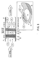
- the oxidizing apparatus 10 for oxidizing carbon monoxide is generally provided for an air cleaner, a smoke separator, a deodorizing equipment (deodorizer), an air conditioner, an air cleaning/ deodorizing system, or the like, or utilized as air cleaner, smoke separator, deodorizer, or air cleaning/deodorizing system itself.
- This oxidizing apparatus 10 for carbon monoxide is an apparatus for deodorizing an odor component in the air and oxidizing carbon monoxide (CO) generated through incomplete combustion at an ordinary temperature so as to reduce or eliminate the concentration thereof.
- the oxidizing apparatus 10 for carbon monoxide of this embodiment comprises a cylindrical casing 11 as a main body, a ventilation path 12 for ventilating the air provided in the casing 11.
- a pre-filter 14 for removing foreign substances such as dust or coarse particles in the air an ozone generating means (ozone generator or ozone generating member) 15 for generating ozone (O 3 ), and a CO oxidizing member (CO oxidizing member or device) 16 for oxidizing carbon monoxide (CO) at an ordinary temperature are provided successively in this order from a side of an air inlet port (air suction port) 13.
- one or more (at least one) blower 17 are disposed at optional positions on the ventilation path 12 of the cylindrical casing 11.
- the carbon monoxide in the air is thus oxidized by the CO oxidizing member 16 at an ordinary temperature to thereby generate carbon dioxide (CO 2 ), and thereafter, the generated CO 2 is discharged from an air outlet (air discharge port) 18 to the outside of the casing 11.
- a discharge photocatalyst module 20 shown in FIG. 2 is used as the ozone generator 15, a discharge photocatalyst module 20 shown in FIG. 2 is used.
- This discharge photocatalyst module 20 is provided with a porous ceramics 22 carrying the photocatalyst at a portion between electric discharge electrodes 21.
- the porous ceramics 22 comprises a photocatalyst carrier for carrying the photocatalyst, and the ultraviolet ray generated by the electric discharge is directly utilized for exciting the photocatalyst.
- Such porous ceramics 22 also acts to carry out a filtering function.
- a disinfecting function by the generated ozone, an oxidizing function and a decomposing function of the photocatalyst by the activating carbon are attained or facilitated, and as a result, the air can be effectively purified and deodorized.
- the odor component can be decomposed by the electric discharge effect, the ozone generation effect and the photocatalyst applying effect by about 10 times, in decomposing performance, in comparison with decomposing effect by a conventional lamp type photocatalyst module.
- the light emission by the electric discharge can be utilized as a light source so that constitutional elements or like such as an active carbon and a lamp, which are required to be exchanged in a long use, can be eliminated, thus realizing a long usable life time.
- the photocatalyst decomposing function can be promoted and the air purifying function and the air deodorizing function can be improved.
- the ozone (O 3 ) generated by the ozone generator 15 is subjected to the air purifying and deodorizing processes in the ozone generating area A and is blown by the blower 17 towards the CO oxidizing member 16.
- the CO oxidizing member 16 comprises an ozone decomposer (decomposing element) 24 for decomposing the generated ozone and then generating an active oxygen (radical oxygen), and a CO adsorber (adsorbing element) 25 for adsorbing the carbon monoxide (CO) generated through the incomplete combustion, which constitute an oxidizing reaction area B for carbon monoxide.
- the ozone decomposer 24 and the CO adsorber 25 are provided in the common CO oxidizing reaction area B so as to carry out the oxidizing reaction of the carbon monoxide (CO) by using the active oxygen.
- the ozone decomposer 24 is made of at least one ozone decomposing substance 27 selected from the group consisting of an oxide of Mn, Cu, or Ni, a porous carbon containing Ni, Co, Mn, or Cu, a zeolite and a clay mineral.
- the ozone decomposing substance 27 is formed itself as a porous member having a honeycomb structure or a three dimensional mesh structure. In this case, since the ozone decomposing means 24 also attains a function as a carrier, so that a base member can be eliminated.
- the CO adsorber 25 constituting the ozone generator 15 is composed of fine particles 28 of at least one platinum based VIII group precious metal selected from the group consisting of platinum, iridium, osmium, palladium, rhodium, and ruthenium.
- the platinum based precious metal fine particles 28 each has a particle size of 10 ⁇ to 1,000 ⁇ , preferably a particle size of 50 ⁇ to 400 ⁇ .
- the fine particles 28 are carried on the ozone decomposing substance 27 as a waste ozone catalyst constituting the CO adsorber 25 as shown in FIG. 3. That is, a large number of such platinum based precious metal fine particles, such as the platinum fine particles 28, are carried densely on the ozone decomposing substance 27 as the waste ozone catalyst so as to form a common CO oxidizing reaction layer or a reaction surface.
- the ozone decomposing substance 27 constitutes a platinum carrying catalyst.
- the ozone decomposing substance 27 constituting the ozone decomposer 24 decomposes the ozone (O 3 ) so as to generate the active oxygen (radical oxygen: O), which has a life time of a 10 -6 to 10 -7 sec order, being extremely short.
- O active oxygen
- CO carbon monoxide
- the active oxygen oxygen atom O
- the oxidizing reaction can be generated at an ordinary temperature. For this reason, it becomes necessary to densely capture a large number of carbon monoxide molecules in the extreme vicinity of the active oxygen generating area through the ozone decomposition.
- a CO adsorbing area D for adsorbing the carbon monoxide (CO) is formed in the ozone decomposing area C composed of the ozone decomposer 24.
- the CO adsorbing area D is a mesh like area composed of the CO adsorber 25 of the fine particle structure.
- the ozone decomposing area C of the ozone decomposer 24 and the CO adsorbing area D of the CO adsorber 25 are commonly formed in the CO oxidizing reaction area B, so that the carbon monoxide generated and captured through the incomplete combustion contacts the active oxygen and easily carry out the oxidizing reaction at an ordinary temperature.
- the carbon monoxide is physiologically extremely poisonous and it couples with hemoglobin in the blood to thereby paralyze or deteriorate its function, its poisoning or toxicity can be removed by oxidizing the carbon monoxide to the carbon dioxide.
- the oxidizing apparatus 10 can oxidize the carbon monoxide generated in the incomplete combustion at an ordinary temperature so as to eliminate the carbon monoxide or remarkably reduce the concentration thereof.
- it is applicable for deodorizing an interior of a vehicle such as passenger car or a taxi as an air purifying (cleaning) and deodorizing device; deodorizing the disinfection odor in a hospital or a residential care institution or like; deodorizing a car refrigerator, a domestic refrigerator, a truck cargo room or the like; deodorizing a toilet and a raw garbage odor; and so on.
- the coarse particles such as dusts and dirt flown into the ventilation path 12 of the casing 11 can be removed by the pre-filter 14 arranged therein.
- the air after the removal of the coarse particles is forcibly blown and guided in the ventilation path 12 by the blower 17 towards the ozone generator 15.
- the ozone is generated through the corona discharge to thereby remove, eliminate or disinfect the odor component in the air through the reaction with the generated ozone.
- the odor component in the air can be decomposed into an odorless component by the disinfecting function due to the ultraviolet ray, the oxidizing function of the generated ozone, the disinfecting function, and the decomposition due to the photocatalyst.
- a combustion gas from cigarette includes, in addition to the CO 2 , carbon monoxide or ammonium by the incomplete combustion, alcohols and aldehydes.
- formaldehyde contained in construction material for buildings ammonium contained in raw garbage odor or food odor, hydrogen sulfide, trimethyl amine, ammonium, acetic acid, acetaldehyde, formaldehyde, trimethyl amine contained in a vehicle interior air, or like.
- the odor components in the air such as ammonium, hydrogen sulfide, trimethyl amine, methyl dioxide, acetaldehyde, formaldehyde, styrene, or like can be decomposed and removed as odorless air while passing through the ozone generating area A in the cylindrical casing 11 of the oxidizing apparatus 10.
- the CO gas as incomplete combustion gas passes through the ozone generating area A as it is and is guided to the CO oxidizing area B.
- the air from which the odor component is removed is guided to the CO oxidizing member or element 16 consisting the CO oxidizing area B together with the carbon monoxide.
- the CO oxidizing member 16 is provided, in the CO oxidizing reaction area B, with the ozone decomposer 24 and the CO adsorber 25 so as to carry out the oxidizing reaction to the carbon monoxide.
- the CO adsorbing area D composed of the CO adsorber 25 is provided in the ozone decomposing area C constituting the ozone decomposer 24.
- the ozone decomposing area C and the CO adsorbing area D thus form the common CO oxidizing reaction area B.
- the CO adsorbing area D in which the fine particles 28 for adsorbing the carbon monoxide (CO) are densely distributed, is provided in the vicinity of the ozone decomposing area C for generating the active oxygen (radical oxygen) by decomposing the ozone (O 3 ).
- the CO adsorber 25 provided for the CO adsorbing area D is composed of the platinum based precious metal fine particles 28, which are carried on the ozone decomposing layer of the ozone decomposing substance 27 formed to the porous member or on the surface of the porous member in a densely distributed state. Therefore, the surface area of the platinum based precious metal fine particles 28 for adsorbing the carbon monoxide can be made larger, and as a result, the CO carrying area (CO adsorbing area) can be made larger.
- the CO adsorbing area D having a large CO carrying area for adsorbing the carbon monoxide (CO) particles can be disposed in the extreme vicinity of the portion or area at which the ozone is generated through the operation of the ozone decomposer 24. Furthermore, the CO adsorber 25 forming the CO adsorbing area D has a large CO carrying area so that the carbon monoxide particles in the air can be effectively captured densely. On the other hand, the CO adsorber 25 carrying a large number of platinum based precious metal fine particles 28 is positioned so that the ozone decomposing layer of the ozone decomposing substance 27 is formed in the vicinity of the fine particles so as to form the common oxidizing reaction layer.
- the active oxygen generated by the ozone decomposer 24 can easily contact the carbon monoxide in the high concentration distribution in the vicinity thereof so as to facilitate the oxidizing reaction. Therefore, in the CO oxidizing element 16, the active oxygen generated by the ozone decomposer 24 can contact the highly concentrated carbon monoxide captured by the CO adsorber 25 to thereby easily facilitate the oxidizing reaction.
- the oxidizing reaction can be promoted only by capturing the carbon monoxide in the extreme vicinity of the active oxygen generating area at which the active ozone is generated by the ozone decomposer 24. That is, it is confirmed for the first time that the carbon monoxide can be oxidized easily by capturing the carbon monoxide at a high concentration in the vicinity of the active oxygen generating portion.
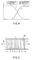
- the carbon monoxide in the use of the carbon monoxide oxidizing apparatus 10 of the characters mentioned above, the carbon monoxide can be subjected to the oxidizing reaction by the active oxygen at an ordinary temperature by passing the air through the ozone generating area A and the CO oxidizing reaction area B of the ventilation path 12, and moreover, the concentration of the carbon monoxide contained in the air discharged from the air outlet 18 of the ventilation path 12 can be made substantially zero as shown by the concentration curve E in FIG. 4. Furthermore, as represented by the concentration curve F in FIG. 4, the carbon dioxide concentration increase through the carbon monoxide oxidizing reaction. The carbon monoxide concentration and the carbon dioxide concentration will be measured by a CO gas concentration meter and a CO 2 gas concentration meter, respectively.
- the carbon monoxide can be oxidized efficiently and effectively at an ordinary temperature so as to produce carbon dioxide. Accordingly, the carbon monoxide concentration can be reduced or made substantially zero by oxidizing the carbon monoxide.
- FIG. 5 is a diagram showing a principal of the second embodiment of an oxidizing apparatus 10A for oxidizing carbon monoxide according to the present invention.
- This carbon monoxide oxidizing apparatus 10A differs from the oxidizing apparatus 10 shown in FIG. 1 in its basic structure. That is, in this oxidizing apparatus 10A of the second embodiment, an electric dust collector 30 is arranged in the downstream side of the pre-filter 14 in the ventilation path 12. The electric dust collector 30 is disposed for the purpose of removing more fine dust or like which cannot be removed by the pre-filter 14.
Landscapes
- Engineering & Computer Science (AREA)
- Environmental & Geological Engineering (AREA)
- Chemical & Material Sciences (AREA)
- Health & Medical Sciences (AREA)
- Biomedical Technology (AREA)
- Analytical Chemistry (AREA)
- General Chemical & Material Sciences (AREA)
- Oil, Petroleum & Natural Gas (AREA)
- Chemical Kinetics & Catalysis (AREA)
- Disinfection, Sterilisation Or Deodorisation Of Air (AREA)
- Exhaust Gas Treatment By Means Of Catalyst (AREA)
Claims (6)
- Verfahren zum Oxidieren von Kohlenmonoxid (CO) in Luft, die in einer Struktur fließt, die einen Weg bildet, wobei das Verfahren folgende Schritte umfaßt:Erzeugung von Ozon in einer ozonerzeugenden Fläche durch Verwendung eines Fotokatalysatormoduls vom Entladungstyp, umfassend ein poröses Keramikmaterial, das einen Fotokatalysator und elektrische Entladungselektroden an jeder Seite des porösen Keramikmaterials trägt, wobei das Ozon zum Desodorieren einer Geruchskomponente der Luft ist;Zersetzen des erzeugten Ozons in einer Ozonzersetzungsfläche durch Verwendung eines Ozonzersetzungsteils; undAdsorbieren und Tragen von Kohlenmonoxid, das durch unvollständige Verbrennung erzeugt ist, in einer CO-Adsorptionsfläche durch Verwendung eines CO-Adsorptionsteils;worin die Ozonzersetzungsfläche und die CO-Absorptionsfläche in einer allgemeinen Oxidationsreaktionsfläche gebildet sind, worin das Kohlenmonoxid durch Verwendung von aktivem Sauerstoff oxidiert wird, der im Ozonzersetzungsschritt in der Oxidationsreaktionsfläche erzeugt ist,worin das Ozonzersetzungsteil aus zumindest einer Ozonzersetzungssubstanz, ausgewählt aus der Gruppe bestehend aus einem Oxid von Mn, Cu oder Ni, einem porösen Kohlenstoff, umfassend Ni, Co, Mn oder Cu, einem Zeolith und einem Lehmmaterial in der Form einer Wabenstruktur oder einer dreidimensionalen Meshstruktur gebildet ist, undworin das Co-Adsorptionsteil sich aus feinen Teilchen aus zumindest einem Edelmetall auf Platinbasis zusammensetzt, ausgewählt aus der Gruppe bestehend aus Platin, Iridium, Osmium, Palladium, Rhodium und Ruthen, wobei die feinen Teilchen durch das Ozonzersetzungsteil getragen werden.
- Verfahren nach Anspruch 1, worin die Luft durch einen Ventilationsweg mit einem Saugteil und einem Entladungsteil fließt, wobei das Verfahren weiterhin den Schritt umfaßt:Desodorieren einer Geruchskomponente in der Luft durch das Ozon, das in der Ozonerzeugungsfläche erzeugt ist;worin die Ozonzersetzungsfläche abwärts der Ozonerzeugungsfläche in dem Ventilationsweg angeordnet ist; undworin die CO-Adsorptionsfläche in dem Ventilationsweg liegt.
- Anlage zur Oxidation von Kohlenmonoxid in Luft, die in einer Struktur fließt, die einen Weg bildet, wobei die Anlage umfaßt:ein Ozonerzeugungsteil, das ein Fotokatalysatormodul vom Entladungstyp ist, umfassend ein poröses Keramikmaterial, das einen Fotokatalysator und elektrische Entladungselektroden an jeder Seite des porösen Keramikmaterials umfaßt und das in dem Weg angeordnet ist, wobei das durch das Teil erzeugte Ozon zum Desodorieren einer Geruchskomponente in der Luft dient;ein Ozonzersetzungsteil, das im Weg zum Zersetzen des Ozons angeordnet ist, zum Erzeugen von aktivem Sauerstoff; undein CO-Adsorptionsteil, das in dem Weg zum Adsorbieren und Tragen von Kohlenmonoxid angeordnet ist, das durch unvollständige Verbrennung erzeugt ist;worin das Ozonzersetzungsteil und das CO-Adsorptionsteil in einer allgemeinen Oxidationsreaktionsfläche angeordnet sind, so daß das Kohlenmonoxid durch den aktiven Sauerstoff oxidiert wird;worin das Ozonzersetzungsteil aus zumindest einer Ozonzersetzungssubstanz erzeugt ist, ausgewählt aus der Gruppe bestehend aus einem Oxid aus Mn, Cu oder Ni, einem porösen Kohlenstoff, umfassend Ni, Co, Mn oder Cu, Zeolith und einem Lehmmaterial in der Form einer Wabenstruktur oder einer dreidimensionalen Meshstruktur, die feine Teilchen trägt, die das CO-Adsorptionsteil ausmachen, undworin das CO-Adsorptionsteil sich aus feinen Teilchen aus zumindest einem Edelmetall auf Platinbasis zusammensetzt, ausgewählt aus der Gruppe bestehend aus Platin, Iridium, Osmium, Palladium, Rhodium und Ruthen, wobei die feinen Teilchen durch das Ozonzersetzungsteil getragen sind.
- Anlage nach Anspruch 3, worin die feinen Teilchen aus dem Edelmetall aus Platinbasis jeweils eine Teilchengröße von 10 bis 1.000 Å haben.
- Anlage nach Anspruch 3, weiterhin umfassend einen Vorfilter, der an der Luftsaugseite in dem Luftfließweg angeordnet ist, zum Entfernen von groben Teilchen aus der Luft, und zumindest ein Blasteil, das an einer Abwärtsseite des Vorfilters in dem Luftfließweg angeordnet ist.
- Anlage nach Anspruch 5, weiterhin umfassend einen elektrischen Staubsammler, der an einer Abwärtsseite des Vorfilters in dem Luftfließweg angeordnet ist, zum Entfernen von feinen groben Teilchen in der Luft.
Priority Applications (2)
| Application Number | Priority Date | Filing Date | Title |
|---|---|---|---|
| DE200460008027 DE602004008027T2 (de) | 2004-03-12 | 2004-03-12 | Verfahren und Vorrichtung zur Oxidation von Kohlenmonoxid |
| EP04005969A EP1574248B1 (de) | 2004-03-12 | 2004-03-12 | Verfahren und Vorrichtung zur Oxidation von Kohlenmonoxid |
Applications Claiming Priority (1)
| Application Number | Priority Date | Filing Date | Title |
|---|---|---|---|
| EP04005969A EP1574248B1 (de) | 2004-03-12 | 2004-03-12 | Verfahren und Vorrichtung zur Oxidation von Kohlenmonoxid |
Publications (2)
| Publication Number | Publication Date |
|---|---|
| EP1574248A1 EP1574248A1 (de) | 2005-09-14 |
| EP1574248B1 true EP1574248B1 (de) | 2007-08-08 |
Family
ID=34814312
Family Applications (1)
| Application Number | Title | Priority Date | Filing Date |
|---|---|---|---|
| EP04005969A Expired - Lifetime EP1574248B1 (de) | 2004-03-12 | 2004-03-12 | Verfahren und Vorrichtung zur Oxidation von Kohlenmonoxid |
Country Status (2)
| Country | Link |
|---|---|
| EP (1) | EP1574248B1 (de) |
| DE (1) | DE602004008027T2 (de) |
Families Citing this family (1)
| Publication number | Priority date | Publication date | Assignee | Title |
|---|---|---|---|---|
| JP5622353B2 (ja) * | 2007-05-07 | 2014-11-12 | 本荘ケミカル株式会社 | 気相中の一酸化炭素を二酸化炭素に光酸化する方法 |
Family Cites Families (3)
| Publication number | Priority date | Publication date | Assignee | Title |
|---|---|---|---|---|
| US5186903A (en) * | 1991-09-27 | 1993-02-16 | North Carolina Center For Scientific Research, Inc. | Apparatus for treating indoor air |
| US5221520A (en) * | 1991-09-27 | 1993-06-22 | North Carolina Center For Scientific Research, Inc. | Apparatus for treating indoor air |
| US5676913A (en) * | 1994-02-18 | 1997-10-14 | Bcp S.R.L. | Mobile apparatus for the purification of polluted air, and process therefor |
-
2004
- 2004-03-12 EP EP04005969A patent/EP1574248B1/de not_active Expired - Lifetime
- 2004-03-12 DE DE200460008027 patent/DE602004008027T2/de not_active Expired - Lifetime
Non-Patent Citations (1)
| Title |
|---|
| None * |
Also Published As
| Publication number | Publication date |
|---|---|
| EP1574248A1 (de) | 2005-09-14 |
| DE602004008027T2 (de) | 2008-04-30 |
| DE602004008027D1 (de) | 2007-09-20 |
Similar Documents
| Publication | Publication Date | Title |
|---|---|---|
| US20040175318A1 (en) | Method and apparatus for oxidizing carbon monoxide | |
| JP3038522B2 (ja) | 空気清浄脱臭環境浄化機 | |
| US5948355A (en) | Air-purifying filter and air-purifier for automobile | |
| US20100086436A1 (en) | Onsite chemistry air filtration system | |
| JPH02207824A (ja) | 空気清浄装置 | |
| JP3402385B2 (ja) | 気体の清浄方法及び装置 | |
| JP2002263175A (ja) | 空気浄化装置 | |
| JPH08253025A (ja) | 自動車用空気清浄脱臭器 | |
| JP3000056B2 (ja) | 空気清浄化装置 | |
| JP2004290882A (ja) | 空気浄化フィルタ及び空気浄化装置 | |
| JPH06190236A (ja) | 気体の清浄方法及び装置 | |
| JPH11221442A (ja) | 複合消臭集塵フィルタ | |
| EP1574248B1 (de) | Verfahren und Vorrichtung zur Oxidation von Kohlenmonoxid | |
| CN100360213C (zh) | 氧化一氧化碳的方法和设备 | |
| JPH0751535A (ja) | 空気清浄器用フィルターの交換方法 | |
| KR100603802B1 (ko) | 일산화 탄소의 산화 방법 및 장치 | |
| JP2000254452A (ja) | 空気清浄機 | |
| JP2003135582A (ja) | 空気浄化装置 | |
| JPH10118519A (ja) | 空気清浄機 | |
| JP2002336645A (ja) | プラズマ触媒反応器、空気浄化装置、窒素酸化物浄化装置、及び燃焼排ガス浄化装置 | |
| JP2000279492A (ja) | ガス分解用構造体並びにこれを用いたガス分解装置及び空気調和装置 | |
| JP4033552B2 (ja) | 空気清浄用フィルタ及びこれを用いた空気清浄器 | |
| JP2001262663A (ja) | トイレ脱臭機 | |
| JP2009297700A (ja) | Co分解機能を有する空気清浄機 | |
| JPH11290693A (ja) | 空気浄化触媒、該空気浄化触媒の製造方法、該空気浄化触媒を用いた触媒構造体及び該触媒構造体を備えた空気調和機 |
Legal Events
| Date | Code | Title | Description |
|---|---|---|---|
| PUAI | Public reference made under article 153(3) epc to a published international application that has entered the european phase |
Free format text: ORIGINAL CODE: 0009012 |
|
| 17P | Request for examination filed |
Effective date: 20040312 |
|
| AK | Designated contracting states |
Kind code of ref document: A1 Designated state(s): AT BE BG CH CY CZ DE DK EE ES FI FR GB GR HU IE IT LI LU MC NL PL PT RO SE SI SK TR |
|
| AX | Request for extension of the european patent |
Extension state: AL LT LV MK |
|
| AKX | Designation fees paid |
Designated state(s): DE FR GB IT |
|
| GRAP | Despatch of communication of intention to grant a patent |
Free format text: ORIGINAL CODE: EPIDOSNIGR1 |
|
| GRAS | Grant fee paid |
Free format text: ORIGINAL CODE: EPIDOSNIGR3 |
|
| GRAA | (expected) grant |
Free format text: ORIGINAL CODE: 0009210 |
|
| AK | Designated contracting states |
Kind code of ref document: B1 Designated state(s): DE FR GB IT |
|
| REG | Reference to a national code |
Ref country code: GB Ref legal event code: FG4D |
|
| REF | Corresponds to: |
Ref document number: 602004008027 Country of ref document: DE Date of ref document: 20070920 Kind code of ref document: P |
|
| ET | Fr: translation filed | ||
| PLBE | No opposition filed within time limit |
Free format text: ORIGINAL CODE: 0009261 |
|
| STAA | Information on the status of an ep patent application or granted ep patent |
Free format text: STATUS: NO OPPOSITION FILED WITHIN TIME LIMIT |
|
| 26N | No opposition filed |
Effective date: 20080509 |
|
| PGFP | Annual fee paid to national office [announced via postgrant information from national office to epo] |
Ref country code: IT Payment date: 20120320 Year of fee payment: 9 |
|
| PGFP | Annual fee paid to national office [announced via postgrant information from national office to epo] |
Ref country code: GB Payment date: 20130306 Year of fee payment: 10 Ref country code: DE Payment date: 20130306 Year of fee payment: 10 Ref country code: FR Payment date: 20130325 Year of fee payment: 10 |
|
| REG | Reference to a national code |
Ref country code: DE Ref legal event code: R119 Ref document number: 602004008027 Country of ref document: DE |
|
| GBPC | Gb: european patent ceased through non-payment of renewal fee |
Effective date: 20140312 |
|
| REG | Reference to a national code |
Ref country code: FR Ref legal event code: ST Effective date: 20141128 |
|
| REG | Reference to a national code |
Ref country code: DE Ref legal event code: R119 Ref document number: 602004008027 Country of ref document: DE Effective date: 20141001 |
|
| PG25 | Lapsed in a contracting state [announced via postgrant information from national office to epo] |
Ref country code: DE Free format text: LAPSE BECAUSE OF NON-PAYMENT OF DUE FEES Effective date: 20141001 Ref country code: GB Free format text: LAPSE BECAUSE OF NON-PAYMENT OF DUE FEES Effective date: 20140312 Ref country code: FR Free format text: LAPSE BECAUSE OF NON-PAYMENT OF DUE FEES Effective date: 20140331 |
|
| PG25 | Lapsed in a contracting state [announced via postgrant information from national office to epo] |
Ref country code: IT Free format text: LAPSE BECAUSE OF NON-PAYMENT OF DUE FEES Effective date: 20140312 |