EP1574659A2 - Barrière modulaire de sécurité - Google Patents
Barrière modulaire de sécurité Download PDFInfo
- Publication number
- EP1574659A2 EP1574659A2 EP05251395A EP05251395A EP1574659A2 EP 1574659 A2 EP1574659 A2 EP 1574659A2 EP 05251395 A EP05251395 A EP 05251395A EP 05251395 A EP05251395 A EP 05251395A EP 1574659 A2 EP1574659 A2 EP 1574659A2
- Authority
- EP
- European Patent Office
- Prior art keywords
- bars
- barrier according
- panel
- barrier
- opening
- Prior art date
- Legal status (The legal status is an assumption and is not a legal conclusion. Google has not performed a legal analysis and makes no representation as to the accuracy of the status listed.)
- Withdrawn
Links
- 230000004888 barrier function Effects 0.000 title claims abstract description 54
- 239000007787 solid Substances 0.000 claims description 4
- 230000037431 insertion Effects 0.000 claims 1
- 238000003780 insertion Methods 0.000 claims 1
- 238000000034 method Methods 0.000 description 4
- 239000000853 adhesive Substances 0.000 description 2
- 230000001070 adhesive effect Effects 0.000 description 2
- 239000000463 material Substances 0.000 description 2
- 241000500845 Costelytra zealandica Species 0.000 description 1
- 239000004677 Nylon Substances 0.000 description 1
- 229910000831 Steel Inorganic materials 0.000 description 1
- 230000004075 alteration Effects 0.000 description 1
- 230000001788 irregular Effects 0.000 description 1
- 238000004519 manufacturing process Methods 0.000 description 1
- 230000013011 mating Effects 0.000 description 1
- 239000002184 metal Substances 0.000 description 1
- 229920001778 nylon Polymers 0.000 description 1
- 239000004033 plastic Substances 0.000 description 1
- 230000000717 retained effect Effects 0.000 description 1
- 239000010959 steel Substances 0.000 description 1
- 238000003466 welding Methods 0.000 description 1
Images


Classifications
-
- E—FIXED CONSTRUCTIONS
- E04—BUILDING
- E04H—BUILDINGS OR LIKE STRUCTURES FOR PARTICULAR PURPOSES; SWIMMING OR SPLASH BATHS OR POOLS; MASTS; FENCING; TENTS OR CANOPIES, IN GENERAL
- E04H17/00—Fencing, e.g. fences, enclosures, corrals
- E04H17/14—Fences constructed of rigid elements, e.g. with additional wire fillings or with posts
- E04H17/16—Fences constructed of rigid elements, e.g. with additional wire fillings or with posts using prefabricated panel-like elements, e.g. wired frames
- E04H17/161—Fences constructed of rigid elements, e.g. with additional wire fillings or with posts using prefabricated panel-like elements, e.g. wired frames using wire panels
-
- E—FIXED CONSTRUCTIONS
- E06—DOORS, WINDOWS, SHUTTERS, OR ROLLER BLINDS IN GENERAL; LADDERS
- E06B—FIXED OR MOVABLE CLOSURES FOR OPENINGS IN BUILDINGS, VEHICLES, FENCES OR LIKE ENCLOSURES IN GENERAL, e.g. DOORS, WINDOWS, BLINDS, GATES
- E06B1/00—Border constructions of openings in walls, floors, or ceilings; Frames to be rigidly mounted in such openings
- E06B1/56—Fastening frames to the border of openings or to similar contiguous frames
- E06B1/60—Fastening frames to the border of openings or to similar contiguous frames by mechanical means, e.g. anchoring means
- E06B1/6046—Clamping means acting perpendicular to the wall opening; Fastening frames by tightening or drawing them against a surface parallel to the opening
-
- E—FIXED CONSTRUCTIONS
- E06—DOORS, WINDOWS, SHUTTERS, OR ROLLER BLINDS IN GENERAL; LADDERS
- E06B—FIXED OR MOVABLE CLOSURES FOR OPENINGS IN BUILDINGS, VEHICLES, FENCES OR LIKE ENCLOSURES IN GENERAL, e.g. DOORS, WINDOWS, BLINDS, GATES
- E06B9/00—Screening or protective devices for wall or similar openings, with or without operating or securing mechanisms; Closures of similar construction
- E06B9/01—Grilles fixed to walls, doors, or windows; Grilles moving with doors or windows; Walls formed as grilles, e.g. claustra
Definitions
- This invention relates to a physical security barrier comprising an interconnection of modules capable of forming a barrier, the size and shape of which can be chosen by a user so as to fit a multitude of different sizes of openings and frames.
- 'barrier' includes, unless the contexts implies otherwise, closures for window or door openings, fences, gates, blinds, grilles, shutters, screens and the like.
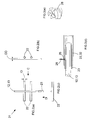
- FIG. 1(a-c) there is shown a panel 11 for a security barrier 10 of the type shown in Figure 4.
- the panel 11 comprises two sets of parallel bars 12,13; each set of bars 12 of the first set extend at an angle (perpendicular) to the bars 13 of the second set of bars.
- the bars 12, 13 form a grid-like panel 11.
- the orientation of the bars 12 are (but not restricted to) vertical and the orientation of the bars 13 are horizontal with reference to the vertical and horizontal coordinates of the opening (not shown) across which they are to be secured.
- the vertical bars 12 extend in the direction B and the horizontal bars 13 extend in the direction A.
- the bars 12, 13 are securely fixed to one another (e.g. welded) at the points of intersection of the bars 12,13 (hereinafter called a 'weld-point' 15).
- the bars 12 or 13 that run parallel to each other are the same length and the ends of the bars are aligned with each other so that if a line was traced from the end of one bar to another, the line would be perpendicular to the direction of the length of the bars 12,13.
- an extension piece 21 comprising a single bar 12 or 13 of the same type and length as either the horizontal 12 or vertical bar 13 in the panel 11 shown in Figure 1(a),and two orthogonal bars each in the form of hollow tube 22 welded at right angles to the bar 12 or 13.
- the tubes 22 of an extension piece 21 are dimensioned to receive the bars 12 or 13 of the panel 11 of Figure 1(a), or the bars 12/13 of other extension pieces 21 of Figure 2(a).
- the tubes 22 are intended to slot onto the bars 12, 13 on an outer edge of a panel 11 to increase the vertical height or horizontal width of the entire barrier 10.
- An extension piece 21 may also consist of only a tube 78 (i.e. no bar) as shown in Figure 7.
- the outer diameters of the bars 12, 13 in any panel 11 are equal so that they may be slotted into the tube 22 of an extension piece 21.
- the inner diameters of the tubes 22 in an extension piece 21 are greater than, or equal to, the outer diameter of the bars, but it is noted that as the discrepancy increases the fit will become progressively looser. It is preferable to have a tight fit with a mind to security, but not too tight so as to hinder the fitting of the extension piece 21 onto the end of a panel 11.
- a nylon sleeve 23 is provided between the bar 12, 13 and each tube 22.
- FIG. 2(d) shows an example of a security screw 28 where the head is of a non-standard type so that only a specific mating tool (not shown) that is not an ordinary cross-head / flat head screwdriver can be used to tighten and loosen it.
- fixing bars 12/13 and tubes 22 are possible in further embodiments of the invention, for example, they may be welded together.
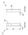
- an attachment member 31 comprising a tube 32 of the same inner diameter as that of the tubes 22 of an extension piece 21.
- the tubes 32 are preferably, but not essentially, of a length (L) equal to, or shorter than, the distance from the end of any outermost bar 12, 13 in a panel 11 to its closest respective weld-point 15.
- the tube 32 is open at one end to receive a bar 12,13 from a panel 11 (or an extension piece 21 that includes bars 12,13).
- the tubes 31 are securely attached (e.g. welded) to a fixing member 33 that facilitates the fixing of the attachment member 31 to structure defining an opening into which the barrier is to be fitted. This permits the security barrier 10 comprising the panels 11 and extension pieces 21 to be attached to a structural surface (for example, the frame of a window) through the use of screws, nails, adhesive or other fixing means.
- a further panel 11 may be fitted to the other side of the extension piece 21 to make up a barrier 10 to fit different sizes of openings.
- Attachment members are then placed on selected bars 12, 13 at both ends of each set of bars and the screws 28 are loosely tightened to stop them falling off.
- the assembled panels 11, extension pieces 21, and the attachment members 31, are offered up to the opening 42 in a wall 44 and the attachment members fixed to the structure (wall 44). This is achieved by sliding each attachment member along the respective bars 12, 13 on which they are mounted (shown by the arrows) to bring them into contact with either the confronting surfaces 42(a) to 42(d) that define the opening 42 in the wall 44 or to overlie the opening 42 by a small distance from the edge of the opening 42,(not shown).
- the screws 28 are then tightened to hold the barrier into place and the attachment members 31 are then secured to the walls of the opening to hold the barrier 10 in the opening.
- panels 11 belonging to a set of panels comprise panels that have the same spacing arrangement, or pitch, between the bars 12 or 13.
- the panels differ with regards to either their horizontal widths or their vertical heights.
- the panel 11 of Figure 5(a) has five vertical bars 12 and three horizontal bars 13.
- the panel 11 of Figure 5(b) also has three horizontal bars 13, but only has two vertical bars 12.
- the vertical bars 12 are the same size as that of the panel 11 of Figure 5(a), but the horizontal bars 13 are truncated to preserve the bar spacing 12 common to that of the panel 11 of Figure 5(a).
- the panel 11 of Figure 5(c) has five vertical bars (as in the panel of Figure 5(a)), but only two horizontal bars.
- the horizontal bars 13 of the panel 11 of Figure 5(c) are the same length as that of the panel 11 of Figure 5(a) and, in this case, it is the vertical bars 12 that are truncated to preserve the spacing between the bars 13.
- a set of panels may also comprise a range of complimentary shaped extension pieces 21 that may be provided to allow the panels 11 of the same set to be joined together in the manner hereinbefore described.
- Barriers 10 can therefore be extended from a base panel size laterally in both the vertical and horizontal directions to set different size openings.
- panels 11 and extension pieces 21 are available as part of a set as shown in Figures 5(a-c), where the height and width of a panel 11 and corresponding extension pieces 21 in any one set is different from those of another set.
- the first set would have a panel 11 with a maximum height and width of 450mm x 300mm and one or more extension pieces 21 having a bar length of 450mm or 350mm and suitable length of tubes 22.
- the second set may comprise of a panel 11 of 600mm x 450mm and one or more extension pieces 21 having a bar length of 600mm or 450mm and suitable length of tubes 22.
- a third set may comprise a panel 11 of dimension 850mm x 675mm, and so on. This enables the selection of different sizes of panels 11 and extension pieces 21 to fit different sizes of openings in structures with minimum additional work.
- a security barrier 10 in the form of a section of a fence secured between two upright posts 61, 62 and two rails 63,64.
- the fence may be made of any desired length by positioning and fixing similar barriers 10 between pairs of posts 61, 62.
- each barrier 10 uses a panel 11 constructed in accordance with that shown in Figure 1. Different lengths of barrier 10, to fit between different gaps between posts 61, 62 can be made by assembling different sizes of panels 11 and/or extension pieces 21 to make up the desired length.
- the barrier 10 is fixed to the respective posts 61, 62 and the rails 63,64 by means of the attachment members 31 (shown in Figure 3) being slid on to the ends of the horizontal bars 13. Where it is desired to fix the fence at the top and bottom ends of selected vertical bars, 12, attachment members 31 may be fixed to selected vertical bars 12.
- a security barrier 10 in the form of a gate 70 secured between two support members 74, 75 and horizontal rails that form part of the gate 70.
- Support member 74, 75 is in the form of a long strip of rigid metal to which is welded a number of tubes 22 similar in size and dimension to the tubes 22 of Figure 2(a) so as to provide a slot into which the bars 12,13 of a panel 11 or extension piece 21 can fit.
- the extension piece 21 is slightly different to that shown in Figure 2??(a), in that the tubes 22 are replaced by bars 13.
- the extension piece 21 has one vertical bar 12 and three horizontal bars.
- the support member 75 on one side of the gate 70 is provided with hinges 77 that cooperate with hinge members 78 provided on an upright post 71 located adjacent to the gate 70.
- the support member 76 on the other side of the gate 70 is provided with a latch and locking mechanism 79 that mates with a keeper 80 recessed into another upright post 72.
- the gate 70 comprises a panel 11 attached to the tubes 22 of the support member 75 on one of its sides attached on the other side by means of connecting pieces to an extension piece 21.
- the extension piece 21 is in turn attached to the support member 74 on the other side of the gate 70.
- the panel 11 comprises three vertical bars 12 and two horizontal bars 13. It is to be understood that in further embodiments of the invention, a panel 11 can comprise one or more bars 12 extending in the vertical direction and one or more bars 13 extending in the horizontal direction although, to maintain a rigid structure, a minimum of at least two bars 12 or 13 is preferable.
- the bars forming the panel 11 may be spaced in a variety of ways, but it is preferred that a uniform spacing is adopted where the distances from the end of any bar 12, 13 to its closest respective weld-point 15 are all equal, and in the case of two or more bars running parallel to each other, for each horizontal or vertical orientation, there is an equal spacing between the bars 12 or 13 of the same orientation on that panel. The distances in the former and latter case do not need to be equal.
- the 12,13 bars are joined together by method of welding.
- other methods of fixing the bars 12, 13 to one another may be used, for example through use of screws, adhesive or other fixing means.
- the bars 12, 13 are made of a material capable of being welded (for example, steel). In further embodiments of the invention, the bars 12, 13 may be made from other materials; a rigid plastic for example.
- the bars 12, 13 may be solid (i.e. do not have a cavity within them) or they may be hollow tubes, or partially hollow.
- the means of adjustment of the barrier 10 is achieved by providing tubes 22 capable of sliding over the bars 12, 13 of a panel (or an extension piece comprising at least one bar). It is to be understood that in further embodiments of the invention, the same adjustability may be achieved by providing tubes in the place of the bars 12, 13 (in the above embodiment) and replacing the tubes 22 with solid rods.
- the tubes 32 of the attachment members 31 may be made of solid rods instead of hollow tubes.
- a panel 11 may comprise a grid-like arrangement of fixed tubes into which the rods 32 of an attachment member 31 may be introduced. The feature of adjustability is provided by the telescopic arrangement of tubes and bars.
- a releasable locking means 65 that can be used with any of the panels 11 and extension pieces 21 described above to enable the barrier 10 to be mounted across an opening in a structure such as, for example a wall in a way that allows the panel to be removed in an emergency.
- the locking means 65 comprises a base plate 66 with a flange 67 normal to the base that is secured to the one or more surfaces 42(a) to (d) of the opening 42, or secured to the inside face 44 (a) of the wall 44 at a location where the attachment members 31 would be positioned.
- the base plate 66 has one or more spaced sockets 68 that are shaped, dimensioned and positioned to receive the fixing member 32 of the, or each, respective attachment member 31 (in the drawing there are two spaced sockets 68).
- Each socket 68 comprises the back plate 67 of the base plate 65 and two spaced side walls 69.
- the open end of the, or each, socket 68 faces towards the space on the inside of the wall 44, that is to say the space on the side of the wall 44 furtherest away from a possible intruder.
- the base plate 66 has a catch 70 for receiving a lockable latch 71on a cover 72 shown in Figure 9.
- the cover 72 has two slots 73 corresponding to the position of the sockets 68. These slots 73 have open ends that face towards the wall 44 (or, where fitted to the surfaces 42(a) to 42(d) towards a possible intruder) so as to retain the attachment members 31 within the locking means against the flange 67 of the base plate.
- attachment members 32 of the embodiments described above are secured to the structure 44 by means of screws or other fasteners those used in the Figure 8 and 9 locking means are not.
- the attachment members 31 are slid into the sockets 68 and retained securely in the locking means against the flange 67 by the cover 72.
- the cover 72 is provided with a key operated latch 76 that engages the catch on the base plate.
Landscapes
- Engineering & Computer Science (AREA)
- Structural Engineering (AREA)
- Architecture (AREA)
- Civil Engineering (AREA)
- Mechanical Engineering (AREA)
- Fencing (AREA)
- Joining Of Building Structures In Genera (AREA)
- Panels For Use In Building Construction (AREA)
Applications Claiming Priority (2)
| Application Number | Priority Date | Filing Date | Title |
|---|---|---|---|
| GB0405232A GB2411923B (en) | 2004-03-09 | 2004-03-09 | Modular security barrier |
| GB0405232 | 2004-03-09 |
Publications (2)
| Publication Number | Publication Date |
|---|---|
| EP1574659A2 true EP1574659A2 (fr) | 2005-09-14 |
| EP1574659A3 EP1574659A3 (fr) | 2008-09-03 |
Family
ID=32117286
Family Applications (1)
| Application Number | Title | Priority Date | Filing Date |
|---|---|---|---|
| EP05251395A Withdrawn EP1574659A3 (fr) | 2004-03-09 | 2005-03-08 | Barrière modulaire de sécurité |
Country Status (2)
| Country | Link |
|---|---|
| EP (1) | EP1574659A3 (fr) |
| GB (1) | GB2411923B (fr) |
Cited By (2)
| Publication number | Priority date | Publication date | Assignee | Title |
|---|---|---|---|---|
| ITBO20080753A1 (it) * | 2008-12-17 | 2010-06-18 | Giorgio Colombarini | Perfezionamenti ad inferriate mobili ed amovibili per porte e finestre. |
| CN102182389A (zh) * | 2010-12-29 | 2011-09-14 | 马健鹉 | 一种钢芯安全网 |
Families Citing this family (1)
| Publication number | Priority date | Publication date | Assignee | Title |
|---|---|---|---|---|
| WO2021006766A2 (fr) * | 2019-07-09 | 2021-01-14 | Юрий Геннадьевич ПУСТОВОЙ | Grille de protection de fenêtre universelle |
Family Cites Families (5)
| Publication number | Priority date | Publication date | Assignee | Title |
|---|---|---|---|---|
| US4162590A (en) * | 1978-01-16 | 1979-07-31 | Earley Vernon A | Burglar bar apparatus |
| AU536676B2 (en) * | 1980-04-16 | 1984-05-17 | Pekshouse, O.C. | Adjustable security grille with sleeve |
| US4416084A (en) * | 1982-05-07 | 1983-11-22 | Giuseppe Zen | Protective device |
| US4817334A (en) * | 1985-02-11 | 1989-04-04 | Palladium Security Products (1985) Inc. | Window bar security system |
| DE19755762C2 (de) * | 1997-12-16 | 2001-03-08 | Siegfried Blank | Sicherungsgitter |
-
2004
- 2004-03-09 GB GB0405232A patent/GB2411923B/en not_active Expired - Fee Related
-
2005
- 2005-03-08 EP EP05251395A patent/EP1574659A3/fr not_active Withdrawn
Cited By (3)
| Publication number | Priority date | Publication date | Assignee | Title |
|---|---|---|---|---|
| ITBO20080753A1 (it) * | 2008-12-17 | 2010-06-18 | Giorgio Colombarini | Perfezionamenti ad inferriate mobili ed amovibili per porte e finestre. |
| CN102182389A (zh) * | 2010-12-29 | 2011-09-14 | 马健鹉 | 一种钢芯安全网 |
| CN102182389B (zh) * | 2010-12-29 | 2013-03-20 | 马健鹉 | 一种钢芯安全网 |
Also Published As
| Publication number | Publication date |
|---|---|
| EP1574659A3 (fr) | 2008-09-03 |
| GB0405232D0 (en) | 2004-04-21 |
| GB2411923B (en) | 2007-11-28 |
| GB2411923A (en) | 2005-09-14 |
Similar Documents
| Publication | Publication Date | Title |
|---|---|---|
| US10422140B2 (en) | Screen enclosure support assembly | |
| EP2707561B1 (fr) | Système de barrière de sécurité | |
| AT518814B1 (de) | Zaunsystem sowie Montageverfahren für ein Zaunsystem | |
| DE202020107451U1 (de) | Trennvorrichtung | |
| US10526842B2 (en) | Mounting arrangement | |
| US20130186264A1 (en) | Architectural mesh forced entry system | |
| EP1574659A2 (fr) | Barrière modulaire de sécurité | |
| US20070158957A1 (en) | Double door security device | |
| EP1182306B1 (fr) | Système de fixation pour éléments de mur à une façade | |
| RU2632377C1 (ru) | Система обеспечения безопасности оконного проема и кронштейн крепления ригеля оконной решетки | |
| DE102007031839A1 (de) | Rahmen zur Staubabdichtung | |
| DE4437319A1 (de) | Einbruchhemmender Schirm für ein Wandelement, einbruchhemmendes Wandelement und einbruchhemmende Wand | |
| DE102016104405B4 (de) | Verfahren zur Montage einer Pfosten-Riegel-Konstruktion und Montagehilfe | |
| DE102023124777A1 (de) | Haltevorrichtung für eine elektronische Einrichtung | |
| EP0360001B1 (fr) | Dispositif de fixation de plaques à un mur, notamment des plaques en céramique | |
| DE19705252C1 (de) | Haltevorrichtung für abgehängte Bauteile | |
| EP0409029B1 (fr) | Profilé pour le support de panneaux de plafond | |
| EP0891459B1 (fr) | Systeme de cloison de separation pour locaux commerciaux | |
| EP1744011A1 (fr) | Support portable pour une fermeture | |
| EP0458730A1 (fr) | Système de sécurité pour le tableau de baie d'une fenêtre | |
| GB2261461A (en) | Barrier apparatus for use in protecting empty unused buildings against vandals | |
| EP4306765B1 (fr) | Panneau latéral pour caisson de store de façade | |
| US20260110203A1 (en) | Door security device | |
| EP1396605A2 (fr) | Fermeture pour orifices muraux | |
| DE202025003593U1 (de) | Anordnung zur Befestigung eines Briefkastens an einem Stabmattenzaun |
Legal Events
| Date | Code | Title | Description |
|---|---|---|---|
| PUAI | Public reference made under article 153(3) epc to a published international application that has entered the european phase |
Free format text: ORIGINAL CODE: 0009012 |
|
| AK | Designated contracting states |
Kind code of ref document: A2 Designated state(s): AT BE BG CH CY CZ DE DK EE ES FI FR GB GR HU IE IS IT LI LT LU MC NL PL PT RO SE SI SK TR |
|
| AX | Request for extension of the european patent |
Extension state: AL BA HR LV MK YU |
|
| PUAL | Search report despatched |
Free format text: ORIGINAL CODE: 0009013 |
|
| AK | Designated contracting states |
Kind code of ref document: A3 Designated state(s): AT BE BG CH CY CZ DE DK EE ES FI FR GB GR HU IE IS IT LI LT LU MC NL PL PT RO SE SI SK TR |
|
| AX | Request for extension of the european patent |
Extension state: AL BA HR LV MK YU |
|
| AKX | Designation fees paid |
Designated state(s): AT BE BG CH CY CZ DE DK EE ES FI FR GB GR HU IE IS IT LI LT LU MC NL PL PT RO SE SI SK TR |
|
| STAA | Information on the status of an ep patent application or granted ep patent |
Free format text: STATUS: THE APPLICATION IS DEEMED TO BE WITHDRAWN |
|
| 18D | Application deemed to be withdrawn |
Effective date: 20090304 |