EP1576230B1 - Systeme permettant de separer une matiere portee par un fluide dudit fluide qui transporte en plus de ladite matiere des particules - Google Patents
Systeme permettant de separer une matiere portee par un fluide dudit fluide qui transporte en plus de ladite matiere des particules Download PDFInfo
- Publication number
- EP1576230B1 EP1576230B1 EP03764559A EP03764559A EP1576230B1 EP 1576230 B1 EP1576230 B1 EP 1576230B1 EP 03764559 A EP03764559 A EP 03764559A EP 03764559 A EP03764559 A EP 03764559A EP 1576230 B1 EP1576230 B1 EP 1576230B1
- Authority
- EP
- European Patent Office
- Prior art keywords
- screen
- fluid
- particulate matter
- drainage passages
- white water
- Prior art date
- Legal status (The legal status is an assumption and is not a legal conclusion. Google has not performed a legal analysis and makes no representation as to the accuracy of the status listed.)
- Expired - Lifetime
Links
Images


Classifications
-
- D—TEXTILES; PAPER
- D21—PAPER-MAKING; PRODUCTION OF CELLULOSE
- D21D—TREATMENT OF THE MATERIALS BEFORE PASSING TO THE PAPER-MAKING MACHINE
- D21D5/00—Purification of the pulp suspension by mechanical means; Apparatus therefor
- D21D5/02—Straining or screening the pulp
-
- B—PERFORMING OPERATIONS; TRANSPORTING
- B07—SEPARATING SOLIDS FROM SOLIDS; SORTING
- B07B—SEPARATING SOLIDS FROM SOLIDS BY SIEVING, SCREENING, SIFTING OR BY USING GAS CURRENTS; SEPARATING BY OTHER DRY METHODS APPLICABLE TO BULK MATERIAL, e.g. LOOSE ARTICLES FIT TO BE HANDLED LIKE BULK MATERIAL
- B07B1/00—Sieving, screening, sifting, or sorting solid materials using networks, gratings, grids, or the like
- B07B1/06—Cone or disc shaped screens
-
- B—PERFORMING OPERATIONS; TRANSPORTING
- B07—SEPARATING SOLIDS FROM SOLIDS; SORTING
- B07B—SEPARATING SOLIDS FROM SOLIDS BY SIEVING, SCREENING, SIFTING OR BY USING GAS CURRENTS; SEPARATING BY OTHER DRY METHODS APPLICABLE TO BULK MATERIAL, e.g. LOOSE ARTICLES FIT TO BE HANDLED LIKE BULK MATERIAL
- B07B1/00—Sieving, screening, sifting, or sorting solid materials using networks, gratings, grids, or the like
- B07B1/18—Drum screens
- B07B1/22—Revolving drums
- B07B1/24—Revolving drums with fixed or moving interior agitators
-
- B—PERFORMING OPERATIONS; TRANSPORTING
- B07—SEPARATING SOLIDS FROM SOLIDS; SORTING
- B07B—SEPARATING SOLIDS FROM SOLIDS BY SIEVING, SCREENING, SIFTING OR BY USING GAS CURRENTS; SEPARATING BY OTHER DRY METHODS APPLICABLE TO BULK MATERIAL, e.g. LOOSE ARTICLES FIT TO BE HANDLED LIKE BULK MATERIAL
- B07B1/00—Sieving, screening, sifting, or sorting solid materials using networks, gratings, grids, or the like
- B07B1/46—Constructional details of screens in general; Cleaning or heating of screens
-
- D—TEXTILES; PAPER
- D21—PAPER-MAKING; PRODUCTION OF CELLULOSE
- D21D—TREATMENT OF THE MATERIALS BEFORE PASSING TO THE PAPER-MAKING MACHINE
- D21D5/00—Purification of the pulp suspension by mechanical means; Apparatus therefor
- D21D5/02—Straining or screening the pulp
- D21D5/06—Rotary screen-drums
-
- D—TEXTILES; PAPER
- D21—PAPER-MAKING; PRODUCTION OF CELLULOSE
- D21F—PAPER-MAKING MACHINES; METHODS OF PRODUCING PAPER THEREON
- D21F1/00—Wet end of machines for making continuous webs of paper
-
- D—TEXTILES; PAPER
- D21—PAPER-MAKING; PRODUCTION OF CELLULOSE
- D21F—PAPER-MAKING MACHINES; METHODS OF PRODUCING PAPER THEREON
- D21F1/00—Wet end of machines for making continuous webs of paper
- D21F1/66—Pulp catching, de-watering, or recovering; Re-use of pulp-water
-
- B—PERFORMING OPERATIONS; TRANSPORTING
- B07—SEPARATING SOLIDS FROM SOLIDS; SORTING
- B07B—SEPARATING SOLIDS FROM SOLIDS BY SIEVING, SCREENING, SIFTING OR BY USING GAS CURRENTS; SEPARATING BY OTHER DRY METHODS APPLICABLE TO BULK MATERIAL, e.g. LOOSE ARTICLES FIT TO BE HANDLED LIKE BULK MATERIAL
- B07B2230/00—Specific aspects relating to the whole B07B subclass
- B07B2230/01—Wet separation
Definitions
- This invention relates to a process for making products such as paper or tissue from pulp or other fiber-containing material, and more particularly to a process for recovering and recirculating usable fibers contained in water produced in such a process.
- the manufacture of products such as paper and tissue uses fibrous material such as wood pulp, which is processed in a known manner to produce the desired end product
- fibrous material such as wood pulp
- the pulp is applied to a screen or papermaking fabric from a headbox, and water is pressed out of the pulp in a known manner to form the paper or tissue, which is dried and formed into a roll.
- the water that is pressed out of the pulp is commonly known as white water, and typically includes small particles of fines and ash material which pass through the fabric along with the water.
- the white water inevitably includes a quantity of usable fibers that pass through or around the papermaking fabric, which are wasted if the white water is discarded.
- DE-A-2924794 upon which the pre-characterizing clause of claim 1 is based, discloses a system for separating fluid-borne material from a fluid that carries particulate matter along with the material, comprising: a screen arrangement including a support and a screen, with drainage passages, wherein the screen defines an interior and an outlet, a fluid supply arrangement configured to direct the fluid outwardly from within the interior of the screen onto the inner surface of the screen, wherein the fluid impinges on the inner surface of the screen at one or more impingement locations, wherein the drainage passages are sized to retain the material on an inner surface defined by the screen and to allow the particulate matter to pass through the drainage passages; and means interconnected with the support for imparting movement to the screen, wherein movement of the screen varies the one or more impingement locations while the fluid is directed outwardly onto the inside surface of the screen by the fluid supply arrangement.
- a system for separating fluid-borne material from a fluid that carries particulate matter along with the material comprising: a screen arrangement including a support and a screen, with drainage passages, wherein the screen defines an interior and an outlet, a fluid supply arrangement configured to direct the fluid outwardly from within the interior of the screen onto the inner surface of the screen, wherein the fluid impinges on the inner surface of the screen at one or more impingement locations, wherein the drainage passages are sized to retain the material on an inner surface defined by the screen and to allow the particulate matter to pass through the drainage passages; and means interconnected with the support for imparting movement to the screen, wherein movement of the screen varies the one or more impingement locations while the fluid is directed outwardly onto the inside surface of the screen by the fluid supply arrangement; characterised in that the screen is suspended from the support, is constructed of a flexible and pliable screen material formed of a series of interwoven strands that define the drainage passages; and
- the present invention further provides a method of separating fluid-borne material from a fluid that carries particulate matter along with the material, comprising the steps of: directing the fluid onto a surface of a flexible screen, wherein the screen defines drainage passages sized to retain the material on the surface of the screen and wherein the drainage passages allow fluid and particulate matter contained within the fluid to pass through the screen, wherein the screen is supported by a support arrangement that is configured to provide outward deflection of the screen where the fluid is directed onto the surface of the screen; and causing movement of the screen while directing the fluid onto the surface of the screen so as to vary the location at which the fluid is directed onto the surface of the screen, wherein the movement of the screen combined with the outward deflection of the screen is operable to alter the configuration of the drainage passages of the screen to dislodge particulate matter contained within the drainage passages, wherein pressure applied to the surface of the screen by the fluid is operable to force particulate matter contained within the drainage passages through the drainage passages to prevent build
- a fiber recovery system for a tissue or papermaking process utilizes a filter or screen, onto which white water from the process is directed at a location downstream of a white water collection vessel forming a part of the papermaking system.
- the screen is sized so as to allow water containing the undesirable or unusable components of the white water, such as fines and ash, to pass through the screen while retaining usable fibers on the screen.
- the water containing the undesirable or unusable material is routed to a wastewater treatment facility, in a conventional manner, and the cleaned water can then be resupplied to the system.
- the screen onto which the white water is directed, is formed of a flexible and pliable screening material, which may be the same type of material as is commonly employed as the fabric in a tissue or papermaking system.
- the screen is supported in a manner such that the screen is maintained relatively loose and flexible, e.g. by suspending the screen from a frame.
- the screen is subjected to motion as the white water is directed onto the screen, which results in flexing of the material of the screen, to provide a self-cleaning action of the screen that prevents plugging and blinding of the screen openings.
- the invention contemplates several different arrangements for supporting and imparting motion to the screen, and for directing the white water onto the screen.
- the white water is applied to an interior area defined by the screen, and the usable fibers are collected on the inner surface of the screen.
- the screen is configured to direct the usable fibers to an open discharge area, where the usable fibers are discharged from the screen.
- the usable fibers are then returned to the system and incorporated into the fibrous material supplied to the headbox, for subsequent application to the tissue or papermaking fabric.
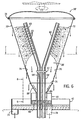
- Figs. 1-3 illustrate a first embodiment of a fiber recovery system, shown generally at 30, in accordance with the present invention, which is particularly well suited for use in a tissue making process.
- fiber recovery system 30 includes a screen 32 suspended from a frame 34 and configured to define a discharge opening 36, in combination with a white water supply system 38 which is operable to direct white water from a papermaking system onto a surface of screen 32.
- Fiber recovery system 3 0 also includes an upwardly open fiber collection vessel or tank 40 located below discharge opening 36 of screen 32, and an upwardly open waste water collection vessel or tank 42.
- Screen 32 is formed of a flexible and pliable screening material, and is frustoconical in shape.
- the material of screen 32 may be of the same type that is used as the fabric in a tissue making process.
- the material of screen 32 is a screen material such as is available from Albany International, Appleton, Wire Division, Appleton, Wisconsin under Model No. M-Weave, Duraform, Z-76 which is a five shed tissue making screen material having a strand count of 3.3/mm (84/in.) (M.D.), 3.3/mm (78/in.) (C.D.), a permeability of 730 CFM and a caliper of 0.41 mm (0.016 inches).
- this type of screen material is representative of various types of screen material that may be employed, depending upon the size of fibers to be collected as well as various other operating parameters.
- the strand size, count and weave pattern of the screen material may vary from the illustrated embodiment. The function of the flexibility and pliability of screen 32 will later be explained.
- Frame 34 includes an outer peripheral frame member 44, which is generally circular, and to which the upper end of screen 32 is connected.
- Frame 34 further includes a series of radial spokes 46 that extend between outer frame member 44 and a hub 48.
- a mounting member 50 is secured to any satisfactory upper support member 52, and includes a rotatable shaft 54 to which hub 48 is connected. In this manner, frame 34 and screen 32 are rotatable about a longitudinal axis of rotation defined by the longitudinal axis of screen 32, which is coincident with the longitudinal axis of shaft 54.
- Screen 32 is configured such that its sides are oriented at an angle of approximately 30° from vertical, so as to define an included angle of approximately 60°.
- screen 32 defines an upper diameter of approximately 48 inches, where screen 32 is connected to outer frame member 44, and discharge opening 36 has a diameter of approximately 7 inches.
- the height of screen 32 is approximately 41 inches. These dimensions are believed to provide sufficient throughput to accommodate the amount of white water generated in most tissue making operations. It is understood that these dimensions and angles are provided to illustrate one embodiment of screen 32 and frame 34 which have been found to provide satisfactory results, and that other dimensions and angles may also be found to function satisfactorily. For example, the size of screen 32 may be increased to accommodate a larger volume of white water that may be generated in higher volume tissue making operations.
- White water supply system 38 is operable to direct white water from a papermaking process onto the inside surface of screen 32.
- white water supply system 38 is in the form of a series of upwardly extending conduits 58, which are centered on a longitudinal axis coincident with the longitudinal axis of screen 32.
- Each conduit 58 is provided with a series of spaced openings 60 along its length, and is closed at its upper end.
- each conduit 58 has an inside diameter of 76 mm (3.0 inches), although it is understood that any other satisfactory conduit size may be employed.
- Conduits 58 extend through brackets 62, which function to maintain the position of conduits 58 relative to each other. Openings 60 in each conduit 58 are arranged in a linear fashion.
- each conduit 58 is radially oriented so as to face in a direction perpendicular to the facing direction of the line of openings 60 in the adjacent conduit 58. As shown in Fig. 2 , each line of openings 60 is oriented so as to face in a direction parallel to and laterally offset from a radius of screen 32. In this manner, each line of openings 60 functions to direct white water onto the inner surface of screen 32 in a direction generally indicated by an arrow 64 ( Fig. 2 ), so that white water impinging on the inner surface of screen 32 applies both a radial force and a tangential force to the inside surface of screen 32.
- each opening 60 is circular in shape, and has a diameter of approximately 9.5 mm (0.375 inches) although it is understood that any other shape and transverse dimension may be employed.
- Conduits 58 extend through a bottom wall 68 defined by fiber collection tank 40, and through a bottom wall 70 defined by waste water collection tank 42. Openings are formed in tank bottom walls 68 and 70 to accommodate passage of conduits 58 therethrough, and appropriate fluid-tight seals are provided between conduits 58 and tank bottom walls 6 8, 70. Alternatively, conduits 58 may be routed laterally outwardly between discharge opening 36 and fiber collection tank 40, to avoid the difficulties and maintenance associated with sealing between conduits 5 8 and walls 68, 70.
- fiber recovery system 30 functions as follows to recover usable fibers from papermaking white water, which is supplied through conduits 58.
- the white water is directed toward the inside surfaces of screen 32 by emission through openings 60 of conduits 58.
- Each line of openings 60 forms a series of linear white water shower streams, so that white water is applied to the inside surfaces of screen 32 generally in a pattern shown at 72.
- the tangential component of the force with which each shower of white water strikes the inside surface of screen 32 functions to impart rotation to screen 32 about its longitudinal axis, by rotation of shaft 54 relative to mounting member 50.
- the speed of rotation of screen 32 is dependent upon the amount of force applied by each shower of white water, which is proportional to the pressure of the white water in conduits 58, as well as the angle of the white water shower streams. Representatively, it has been found that satisfactory operation is obtained by maintaining a low pressure of (e.g. 5 psi) in conduits 58 functions to apply a force to screen 32 which causes screen 32 to rotate at a speed of approximately 40
- the openings of screen 32 are sized to retain usable fibers on the inside surface of screen 32, and to allow water and waste material contained within the white water, such as fines and ash, to pass through the openings of screen 32.
- the waste water passes through screen 32 to the exterior of screen 32, and falls by gravity into waste water collection tank 42.
- the waste water may also travel down the outside surfaces of screen 32.
- a shirt is provided at the lower end of screen 32 so as to direct the waste water outwardly into waste water collection tank 42.
- the waste water is then routed through a waste water outlet 74 of waste water collection tank 42 to a waste water treatment system, where the solids are removed and the cleaned water can be recirculated into the papermaking process.
- the layer of usable fibers collected on the inside surface of screen 32 is representatively illustrated at 76.
- the centrifugal forces due to rotation of screen 32 function to expel additional water and waste material through the openings of screen 32 as the usable fibers advance toward discharge opening 36.
- the usable fibers that are discharged through discharge opening 36 are of a relatively thick consistency, having most of the waste water expelled therefrom.
- the usable fibers are collected in fiber collection tank 40, and are routed through a fiber discharge outlet 78 of collection tank 40 to a pump, which recirculates the usable fibers into the papermaking process.
- fiber recovery system 30 may be installed above chest level, such that gravity flow is employed in place of a pumping operation to recirculate the usable fibers.
- the white water may be applied to screen 32 in various other ways, and examples are illustrated in Figs. 4 and 5 .
- two supply conduits 58 may be employed to apply the white water to screen 32 in place of the four conduits 58 as illustrated in Figs. 2 and 3 .
- the openings 60 in conduits 58 are arranged so as to be offset relative to the center of screen 32 and relative to radii of screen 32, to apply the showers to screen 32 with a tangential force to impart rotation to screen 32.
- Fig. 5 illustrates another embodiment, in which white water is supplied through a single conduit 80, with a series of elbows 82 that provide the radial offset of the shower to apply a tangential force to screen 32 so as to impart rotation to screen 32.
- Figs. 1-5 illustrate a certain embodiment of the invention
- rotation to screen 32 may be accomplished by use of a motor, to ensure that screen 32 rotates at a desired speed.
- the white water showers are preferably applied to the screen in a radial manner, to thereby eliminate the tangential component of the force applied by the shower.
- screen 32 has been illustrated as having a straight-sided frustoconical configuration, it is also considered that the sides of screen 32 may have a convex or concave configuration if desired.
- the white water may also be applied to the inside surface of the screen in any location and in any manner, and the illustrated embodiments are understood to simply be representative of a variety of ways by which the white water may be applied. While the drawings illustrate the use of four showers to apply white water to the screen, it is understood that any desired number and size of showers may be employed.
- the flexibility of screen 32 enables screen 32 to deform from its normal shape during operation as white water is directed onto and strikes screen 32.
- the four showers applied to screen 32 function to deflect the portions of the screen outwardly where the white water showers are applied, to provide generally convex arcuate side areas between the outwardly deformed areas.
- This flexibility and pliability of the screen material provides a "self-cleaning" action of the screen, in that the individual strands of screen material flex and bend to prevent the build-up of material in the corners of the screen openings, which can result in plugging of the screen openings and "blinding" of the screen.
- Fiber recovery system 30 thus requires very little maintenance, while providing an extremely effective and efficient system for collecting usable fibers and separating out unusable material.
- Figs. 6-8 illustrate an alternative embodiment of a fiber recovery system, shown generally at 30', which is generally similar to fiber recovery system 30 as illustrated and described previously. Like reference characters will be used where possible to facilitate clarity.
- each conduit 58' includes a lower section located below bracket 62, and an upper section 83 which is angled outwardly relative to the lower section.
- Upper sections 83 of conduits 58' diverge in an upward direction, and each upper section 83 is oriented substantially parallel to the side of screen 32 so that the streams of white water discharged from openings 60 are applied in a substantially perpendicular direction to screen 32. This orientation of conduit upper sections 83 functions to provide a more efficient and direct application of white water to the inside surface of screen 32.
- the white water may be applied to the inside surface of screen 32 in a non-perpendicular orientation, such that the flow of the white water includes a force component that is parallel to the plane of screen 32 when the white water strikes the surface of screen 32.
- the parallel force component of the white water has a tendency to deform the drainage canals of the material of screen 32 from a generally square or rectangular configuration to a diamond-shaped configuration. This deformation of the drainage canals of screen 32 further assists in providing the self-cleaning action of screen 32 by preventing the buildup of material in the corner regions of the drainage canals.
- each conduit upper section 83 has two lines of openings 60.
- One of the lines of openings 60 is oriented so as to apply a line of white water streams S 1 which is directed outwardly in a radial direction relative to the center of screen 32.
- Each conduit upper section 83 further includes an additional line of openings 60 that is angled relative to the radially facing line of openings 60.
- the second line of openings is positioned so as to emit a series of streams S 2 .
- Each stream S 2 is oriented at an angle of approximately 45° relative to the streams S 1 , and each stream S 2 strikes the inside surface of screen 32 so as to apply a force having both a radial and a tangential component to the inside surface of screen 32.
- Streams S 2 thus function to impart rotation to screen 32 due to the presence of the tangential force component.
- the emission of two separate streams from each conduit upper section 83 functions to apply white water throughout a significant portion of the interior surface of screen 32, to maximize the surface area of screen 32 to which white water is applied.
- a lower section 85 is secured to the bottom end of screen 32 at discharge opening 36.
- Lower section 85 is secured to screen 32 via a skirt 87.
- Lower section 85 functions to increase the overall screen surface area, and routes usable fiber material inwardly to an outlet 89 at its lower end, which surrounds conduits 58'.
- lower section 85 may include a series of flaps 91 separated by slits 93.
- Usable fibers are discharged into fiber collection tank 38 through slits 93. In operation, fibers are collected on the inside surface of lower section 85, and skirt 87 functions to route waste water outwardly beyond the walls of fiber collection tank 40, to prevent waste water from falling into fiber collection tank 40.
- Fig. 9 illustrates an alternative white water supply system 38", which includes angled upper conduit sections 83 as shown in Figs. 6 and 7 .
- white water supply system 38" includes a single supply conduit 95 which extends upwardly into the lower area of screen 32, and supplies white water to a manifold 97 secured to the upper end of conduit 95.
- Angled upper conduit sections 83 are in turn connected to manifold 97, and receive white water from manifold 97 for application through openings 60 to the inside surface of screen 32 in the manner as described previously.
- a single pipe is required to supply white water to the recovery system as opposed to the multiple pipes illustrated in the prior embodiments.
- funnel section 85 can be sized such that its discharge 89 conforms relatively closely to the exterior surface of conduit 95, to further provide additional control for the discharge of usable fibers from funnel section 85.
- Fig. 9A illustrates a full cross-sectional view of the white water supply system 38" shown in Fig. 9 , and also illustrates an alternative system for supporting screen 32.
- a vertical support in the form of a mast 99 is located in the interior of screen 32 for rotatably supporting screen 32 from below rather than from above as illustrated in Figs. 1 and 6 .
- Mast 99 defines a lower end that is mounted to an upwardly facing surface defined by manifold 97, so that screen 32 is supported from manifold 97.
- a hub 101 is rotatably mounted to the upper end of mast 99, and frame 34 is interconnected with hub 101 by spokes or in any other satisfactory manner.
- the fiber recovery system of the present invention is a generally self-contained system that does not require external support, to enable the system to be produced off-site and then installed on-site simply by making appropriate plumbing connections with the white water, waste water and fiber recovery piping of the tissue or papermaking facility.
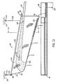
- Figs. 10 , 11 , 12A and 12B illustrate an alternative fiber recovery system in accordance with the present invention, shown generally at 84.
- a screen 86 is suspended from a frame 88 having an open discharge end 90.
- a white water supply conduit 92 directs papermaking white water onto screen 86.
- a fiber collection tank 94 is located below discharge end 90 of screen 86, and a waste water collection tank 96 is located below the remainder of the length of screen 86.
- Frame 88 is generally rectangular in plan, and includes a pair of end frame members 98 and a pair of side frame members 100.
- Screen 86 is formed of the same type of material as screen 32.
- Screen 86 has a channel or trough configuration, defining a closed end 102, and a pair of sloped side walls 104 that converge at a trough bottom 106.
- Screen 86 is oriented such that trough bottom 106 slopes downwardly in a direction toward discharge end 90.
- White water supply conduit 92 defines an outlet 108 which directs white water onto the inside surface of screen 86 in the direction of an arrow shown at 110.
- Outlet 108 of conduit 92 is located toward the discharge end of screen 86, and the pressure of white water within conduit 92 is such that, upon discharge from outlet 108, the white water strikes the inside surfaces of screen 86 at its side wall 104 in close proximity to closed end 102, and is deflected onto closed end 102 and bottom 106.
- Frame 88 is supported in a manner which allows frame 88 and screen 86 to be movable.
- frame 88 is supported in a suspension-type manner using cables 112 and rings 114, which in turn are connected to suitable upper supports 116.
- frame 88 and screen 86 are adapted to be moved in a longitudinal, axial direction in a back and forth manner, while white water is applied to the inside surfaces of screen 86 through conduit 92.
- tissue or papermaking white water is applied to the inside surfaces of screen 86 as shown in Fig. 11 , through outlet 108 of conduit 92.
- the openings of screen 86 are sized to retain usable material contained within the white water on the inside surfaces of screen 86.
- the waste water including the unusable material such as fines and ash, passes through screen 86 and is collected in waste water collection tank 96.
- screen 86 is moved in a back and forth, axial manner while white water continues to be applied to the inside surfaces of screen 86.
- the back and forth movement of screen 86 is carried out in any satisfactory manner, preferably in an automated manner by operation of a motor with an intermittent driver, such as a cam-type actuator or the like.
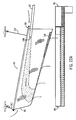
- frame 96 is pushed rearwardly to a position as shown in Fig. 12A , and is then allowed to swing forwardly under its own weight, which includes the weight of frame 88, screen 86, and the material retained on screen 86.
- This movement of screen 86 accomplishes numerous functions.
- the usable fibers which are collected in the trough of screen 86 on screen bottom 106 and the lower areas of side walls 104, are advanced forwardly toward discharge openings 90 when screen 86 is swung forwardly as shown in Fig. 12B . This causes the endmost portion of the collected fibers, shown at 118, to pass through discharge opening 90 for supply to fiber collection tank 94.
- screen 86 causes the screen material to bend and flex, which provides the self-cleaning action as described above.
- the screen movement also varies the location at which the white water strikes the inside surfaces of screen 86, which again causes the screen material to locally bend and flex, to self-clean the screen.
- waste water and undesirable or unusable waste material contained within the white water continues to be separated from the fibers and discharged into waste water collection tank 96.
- the waste water is routed to a waste water treatment facility for removal of undesirable material, and recirculation of the cleaned water into the system.
- the collected usable fibers in fiber collection tank 94 are again recirculated into the system through an outlet 120 associated with fiber collection tank 94.
- Fig. 13 illustrates a single conduit 92 arranged to direct white water onto a side wall 104 of screen 86.
- a pair of conduits 92' may be arranged in a side-by-side manner, and spaced apart linear openings formed in the conduits 92' so as to direct a shower of white water onto the side walls 104 of screen 86.
- Fig. 15 illustrates the use of four white water supply conduits 92' for directing white water showers onto the side walls 104 of screen 86.
- Fig. 16 illustrates an arrangement similar to Fig. 10 , but incorporating a pair of bottom frame members 122 which assist in forming the collected fiber material in the bottom area of screen 86.
- screen 86 may be moved in a side-to-side manner to provide the same functions as set forth above. Again, this is accomplished by applying a lateral force to frame 88, either continuously or intermittently, to impart movement to screen 86. Such movement of screen 86 functions to roll the collected fibers in the bottom of the trough defined by screen 86, to form a fiber roll or log 122.
- the downward slope of screen bottom 106 functions to advance fiber roll or log 122 toward discharge outlet 90 as screen 86 is moved in a side-to-side manner.
- Fig. 18 illustrates another alternative arrangement, in which the side walls 104 of screen 86 are formed with extensions 124.
- the side wall extensions 124 are alternately extended and retracted, which results in the alternate lengthening and shortening of the screen side walls 104.
- frame 88 twists about its longitudinal axis while screen 86 is moved to vary the location at which the white water strikes screen 86, to flex and self-clean screen 86, and to advance fiber roll or log 122 towards screen discharge outlet 90.
- Fig. 19 illustrates an arrangement in which a fiber discharge conduit 126 is located at the discharge outlet 90 of screen 86.
- the usable fibers advanced toward discharge outlet 90 are routed directly into the inlet of fiber discharge conduit 126, to eliminate the use of fiber collection tank 94 and to route the usable fibers directly back into the papermaking process.
- Fig. 20 illustrates the use of a rigid frame member 126 located at discharge outlet 90 of screen 86. This arrangement functions to create a fiber collection pocket at the bottom end of screen 86 adjacent discharge outlet 90, to form a dam over which the collected fiber material is discharged.
- Fig. 21 shows white water supply conduit 92 having outlet 108 through which the stream of white water is discharged for application to the inside surfaces of screen 86. It is also contemplated that the location at which the white water impinges upon screen 86 can be varied by varying the location of the flow rather than varying the position of the screen.
- a flow deflector 130 may be mounted to conduit 92, having a fin 132 located in the white water flow path. Fin 132 is configured to move in response to the impingement of white water onto fin 132, to move the white water flow as it is directed toward screen 86.
- Figs. 24A and 24B illustrate a flexible nozzle 134 mounted to the end of conduit 92. Nozzle 134 is formed of a flexible material such as rubber, and functions to move upwardly and downwardly in response to the emission of white water through its outlet so as to vary the location at which the white water impinges upon the inside surfaces of screen 86.
- Fig. 25 illustrates white water supply conduits such as 58 or 92', having spaced openings 60 for providing a white water shower onto the inside surfaces of a screen, such as 32 or 86. Openings 60 are illustrated as being circular. As shown in Fig. 26 , the openings may also be in the form of straight transverse slots 136, or, as shown in Fig. 27 , in the form of V-shaped slots 138, to provide different shower configurations for applying the white water to the screen.
- the particular shape and configuration of the screen may vary from the illustrated embodiment.
- Frame 88 may take any desired shape, and may be supported in any satisfactory manner.
- the white water may be applied to the screen using the various illustrated white water supply arrangements, or any other arrangement as desired. While the screen is shown and described as being movable either axially or transversely, it is understood that a combination of axial and transverse movement may also be employed.
- the present invention may be employed to screen any type of fluid-borne particles, and is not limited to use in a tissue or papermaking white water screening application.
- Fig. 28 illustrates a representative tissue or papermaking system in which the fiber recovery system of the present invention, shown at 30 and 84, may be incorporated.
- fiber recovery system 30, 84 is located downstream of the wire pit 150 and felt pit 152, which collects white water discharged through the fabric 154.
- the recovered fiber material is supplied to the machine chest 158 through an appropriate supply pipe 160, which supplies the recovered fibers into the supply stream for ultimate supply to the head box 162 of the tissue or papermaking machine.
- any number of fiber recovery systems such as 30, 84 may be used according to the size of the tissue or papermaking system and the volume of white water produced in the system, to recover all of the usable fibers contained in the white water and to purge the system of small particulate material such as fines and ash.
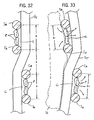
- Figs. 29-33 illustrate a representative embodiment of the material used to construct screens 32 and 86.
- the screen material may be a five shed tissue making screen material, although it is understood that any other screen material configuration may be employed.
- the screen material includes axial strands S A and transverse strands S T , which are woven together in a known manner and which cooperate to define generally rectangular drainage openings or canals C that extend throughout the thickness of the screen material.
- the screen material is selected so that the dimensions of canals C allow the fines and ash material contained within the white water to pass through canals C, and to retain the usable fibers contained in the white water on the inside surface of the screen material in fiber layer 76. As shown in Figs.
- the fiber layer 76 is formed on the inside surface of the screen material such that the area of fiber layer 76 that overlies each canal C extends partially into the canal C.
- This outward formation of fiber layer 76 into canals C functions to anchor fiber layer 76 onto the screen material.
- the area of the screen material is subjected to outward pressure, such as when the area of the screen material passes through the area at which the white water showers are located, the pressure of the applied white water functions to disrupt the individual fibers of the fiber layer 76 as well as the anchor of the fiber layer 76 onto the screen material, which enables fiber layer 76 to move downwardly on the screen material toward the screen discharge area.
- the outward pressure applied to the screen material functions to deflect or deform the screen material outwardly, as noted previously, to increase the degree of curvature of the screen material.
- Such outward deflection or deformation of the screen material causes the flexing action of the screen as noted above, which creates an alteration in the shape of the drainage canals C.
- This results in the self-cleaning function of the screen material in that the alteration in the shape of the drainage canals C prevents the build-up of fines and ash material in the corners of drainage canals C.
- Figs. 32 and 33 illustrate this action. As shown in Fig.
- particles P of fines and ash material tend to become trapped between the strands of the screen material when the screen material is in a flat or slightly curved configuration, such as between the areas where the showers of white water are applied to the interior of the screen material.
- the screen material is deflected outwardly to increase the curvature of the screen material and to simultaneously subject the inside surface of the screen material and fiber layer 76 to the pressure of the applied shower.
- Such outward deflection of the screen material alters the surfaces of the strands that defines the drainage canals C to loosen any particles P that may be caught within a drainage canal C between adjacent strands. As shown in Figs.
- the strands of the screen material are normally separated by a space designated A.
- A As the screen material is flexed, the inside strands move slightly together to a spacing shown at A-, and the outside strands are moved slightly apart to a spacing shown at A+.
- Such movement of the strands together and apart functions to dislodge particles from the corners of the drainage canals C, and the dislodged particles are subjected to the pressure of the white water shower or to the pressure applied by the shower to the fibers incorporated into the fiber layer 76, to force the dislodged particles outwardly for discharge from the drainage canals C.
- This action prevents particles such as P from building up between the strands, to prevent plugging of the drainage canals C and to thus eliminate the downtime and extra equipment required for cleaning screen equipment as is required by the prior art.
- the screen with the fiber layer 76 applied to the inside surface assumes a flat or less curved configuration.
- Fiber layer 76 tends to retain the greater curvature due to the interlocking of the fibers at the time the fiber layer is formed, such that the flattening of the material of the screen thus functions to dislodge the fiber layer 76 from the screen material.
- the fiber layer 76 is able to move by gravity relative to the inside surface of the screen material toward the screen discharge area when the screen material is located between the shower application areas.
- the screen may be backflushed occasionally as desired, such as by application of air or water to the outside of the screen, in order to clean the screen as needed.
Landscapes
- Engineering & Computer Science (AREA)
- Mechanical Engineering (AREA)
- Paper (AREA)
- Separation Of Solids By Using Liquids Or Pneumatic Power (AREA)
- Treatment Of Liquids With Adsorbents In General (AREA)
- Filtration Of Liquid (AREA)
- Extraction Or Liquid Replacement (AREA)
Claims (19)
- Système permettant de séparer une matière portée par un fluide dudit fluide qui transporte des particules en plus de ladite matière, comprenant :un agencement d'un écran comprenant un support (34) et un écran (32), muni de passages d'écoulement, dans lequel l'écran (32) définit un espace interne et une sortie (36),un système d'alimentation en fluide (38) configuré pour diriger le fluide vers l'extérieur à partir de l'intérieur de l'écran (32) vers la surface interne de l'écran (32), dans lequel le fluide entre en contact avec la surface interne de l'écran (32) à un ou plusieurs points d'impact, dans lequel les passages d'écoulement possèdent une taille prévue pour retenir la matière sur une surface interne définie par l'écran (32) et pour permettre aux particules de se déplacer à travers les passages d'écoulement ; etun moyen relié au support (34) qui confère un mouvement à l'écran (32), dans lequel le mouvement de l'écran (32) modifie un ou plusieurs points d'impact lorsque le fluide est dirigé vers l'extérieur sur la surface interne de l'écran (32) par le système d'alimentation en fluide (38) ;caractérisé en ce que l'écran est suspendu au support (34), est construit en matériau d'écran flexible et pliable, formé d'une série de fils entrelacés qui définissent les passages d'écoulement ; et est configuré pour défléchir vers l'extérieur au niveau du ou des points d'impact,
dans lequel la déflection extérieure de l'écran (32) lors du mouvement de l'écran passe le ou les points d'impact, sert à modifier la configuration des passages d'écoulement pour déloger toute particule située dans les passages d'écoulement, et dans lequel la pression exercée par le système d'alimentation en fluide (38) à ce ou ces points d'impact sert à forcer les particules situées dans les passages d'écoulement à se déplacer à travers ceux-ci afin de prévenir l'accumulation de particules dans les passages d'écoulement. - Système selon la revendication 1, dans lequel le support comprend un système de cadre (34), dans lequel ledit système de cadre (34) est relié à une extrémité supérieure définie par l'écran (32) et dans lequel l'écran (32) définit un espace inférieur situé en dessous du système de cadre qui n'est pas soutenu.
- Système selon la revendication 2, dans lequel l'écran (32) définit une configuration conique possédant une extrémité supérieure reliée au système de cadre (34) et une extrémité inférieure (36) définissant la sortie, et dans lequel le moyen permettant de conférer un mouvement à l'écran (32) comprend un moyen (50) permettant de faire tourner le système de cadre sur un axe de rotation généralement vertical coïncidant avec un axe longitudinal défini par l'écran (32).
- Système selon la revendication 3, dans lequel le système d'alimentation en fluide comprend une structure de conduits (38) située dans l'espace interne défini par l'écran (32), dans lequel la structure de conduits comprend une série d'ouvertures à travers lesquelles le fluide est appliqué sur la surface interne de l'écran.
- Système selon la revendication 4, dans lequel les ouvertures dans la structure de conduits sont configurées de façon à exercer une force sur la surface interne de l'écran (32), conférant une rotation à l'écran (32) sur l'axe de rotation du système de cadre.
- Système selon la revendication 2, dans lequel le système de cadre (88) et l'écran (86) sont configurés de telle sorte que l'écran (86) est suspendu au cadre (88) et définit une cuve ouverte sur le haut et possédant une extrémité ouverte définissant la sortie de l'écran (86).
- Système selon la revendication 6, dans lequel le moyen permettant de conférer un mouvement à l'écran (86) comprend un moyen permettant de modifier l'endroit vers lequel le fluide est dirigé sur l'écran (86).
- Système selon la revendication 7, dans lequel le moyen permettant de conférer un mouvement à l'écran (86) comprend un moyen permettant de faire tourner le système de cadre (88) afin de conférer un mouvement à l'écran (86) lorsque le fluide est dirigé sur la surface de l'écran (86).
- Système selon la revendication 8, dans lequel le moyen permettant de conférer un mouvement à l'écran (86) peut fonctionner pour mouvoir l'écran (86) dans une direction transversale à un axe longitudinal défini par la cuve, dans lequel le mouvement transversal de l'écran (86) peut faire rouler la matière dans la cuve, ou mouvoir l'écran (86) dans une direction axiale le long d'un axe longitudinal défini par la cuve.
- Système selon la revendication 9, dans lequel le système de cadre (88) et l'écran (86) sont configurés de telle sorte que la cuve définit une surface inférieure inclinée vers le bas (106) allant vers la sortie, pour aider à diriger la matière vers la sortie lors du mouvement de l'écran (86).
- Procédé permettant de séparer une matière portée par un fluide dudit fluide qui transporte des particules en plus de ladite matière, comprenant les étapes consistant à:diriger le fluide sur la surface d'un écran flexible (32), l'écran (32) définissant des passages d'écoulement ayant une taille prévue pour retenir la matière sur la surface de l'écran (32) et les passages d'écoulement permettant au fluide et aux particules contenues dans le fluide de passer à travers l'écran (32), l'écran étant soutenu par un système de support (34) qui est configuré pour fournir une déflection extérieure de l'écran (32) à l'endroit où le fluide est dirigé sur la surface de l'écran (32) ; et àconférer un mouvement à l'écran (32) tout en dirigeant le fluide sur la surface de l'écran (32) afin de modifier l'endroit vers lequel le fluide est dirigé sur la surface de l'écran (32), le mouvement de l'écran (32) associé à la déflection extérieure de l'écran (32) modifiant la configuration des passages d'écoulement de l'écran (32) pour déloger les particules contenues dans les passages d'écoulement, la pression exercée sur la surface de l'écran (32) par le fluide forçant les particules contenues dans les passages d'écoulement à se déplacer à travers les passages d'écoulement afin de prévenir l'accumulation de particules dans les passages de l'écran.
- Procédé selon la revendication 11, comprenant en outre l'étape consistant à récolter la matière à partir d'une zone de décharge définie par l'écran (32).
- Procédé selon la revendication 11, dans lequel l'étape consistant à provoquer le mouvement de l'écran flexible (32) est réalisée par la modification de l'endroit vers lequel le fluide servant à la fabrication du papier est dirigé sur la surface de l'écran (32).
- Procédé selon la revendication 13, dans lequel l'étape consistant à provoquer le mouvement de l'écran flexible (32) est réalisée en conférant un mouvement à l'écran à travers un système de cadre (34) auquel l'écran (32) est suspendu.
- Procédé selon la revendication 14, dans lequel l'écran est configuré pour définir une forme conique possédant une extrémité inférieure ouverte (36) définissant la zone de décharge de l'écran (32) et dans lequel le système de cadre (34) est situé au niveau d'une extrémité supérieure définie par l'écran (32), et dans lequel l'étape consistant à diriger le fluide sur la surface de l'écran (32) est réalisée en dirigeant le fluide vers l'extérieur vers une surface interne définie par l'écran (32) à partir d'un point de l'espace interne défini par l'écran (32).
- Procédé selon la revendication 15, dans lequel l'étape consistant à conférer un mouvement à l'écran est réalisée en faisant tourner le système de cadre (34) lorsque le fluide est dirigé sur la surface interne de l'écran (32).
- Procédé selon la revendication 16, dans lequel l'étape consistant à conférer un mouvement de rotation à l'écran (32) est réalisée en dirigeant le fluide de façon tangentielle contre la surface interne de l'écran (32).
- Procédé selon la revendication 14, dans lequel l'écran (86) est suspendu au système de cadre (88) et dans lequel l'écran (86) et le système de cadre (88) sont configurés de telle sorte que l'écran (86) définit une configuration de cuve possédant une extrémité ouverte définissant la zone de décharge de l'écran (86), et dans lequel l'étape consistant à diriger le fluide sur la surface de l'écran (86) est réalisée en appliquant le fluide sur les zones latérales définies par la configuration de cuve de l'écran (86).
- Procédé selon la revendication 18, comprenant en outre l'étape consistant à orienter l'écran (86) de sorte que la cuve de l'écran (86) définisse un mur inférieur incliné vers le bas (106) menant à l'extrémité ouverte de l'écran (86), afin d'aider à diriger la matière vers la zone de décharge de l'écran (86).
Applications Claiming Priority (5)
| Application Number | Priority Date | Filing Date | Title |
|---|---|---|---|
| US10/194,785 US6622868B1 (en) | 2002-07-12 | 2002-07-12 | System for recovering and recycling usable fibers from white water in a papermaking process |
| US194785 | 2002-07-12 | ||
| US10/617,286 US7055697B2 (en) | 2002-07-12 | 2003-07-10 | System for separating fluid-borne material from a fluid that carries particulate matter along with the material |
| US617286 | 2003-07-10 | ||
| PCT/US2003/021808 WO2004007835A2 (fr) | 2002-07-12 | 2003-07-11 | Systeme permettant de separer une matiere portee par un fluide dudit fluide qui transporte en plus de ladite matiere des particules |
Publications (2)
| Publication Number | Publication Date |
|---|---|
| EP1576230A2 EP1576230A2 (fr) | 2005-09-21 |
| EP1576230B1 true EP1576230B1 (fr) | 2008-03-12 |
Family
ID=30117832
Family Applications (1)
| Application Number | Title | Priority Date | Filing Date |
|---|---|---|---|
| EP03764559A Expired - Lifetime EP1576230B1 (fr) | 2002-07-12 | 2003-07-11 | Systeme permettant de separer une matiere portee par un fluide dudit fluide qui transporte en plus de ladite matiere des particules |
Country Status (11)
| Country | Link |
|---|---|
| EP (1) | EP1576230B1 (fr) |
| JP (1) | JP4150720B2 (fr) |
| KR (1) | KR100721493B1 (fr) |
| AT (1) | ATE389053T1 (fr) |
| AU (1) | AU2003256514A1 (fr) |
| BR (1) | BR0312558B1 (fr) |
| CA (1) | CA2492202C (fr) |
| DE (1) | DE60319736T2 (fr) |
| ES (1) | ES2301829T3 (fr) |
| MX (1) | MXPA05000520A (fr) |
| WO (1) | WO2004007835A2 (fr) |
Families Citing this family (4)
| Publication number | Priority date | Publication date | Assignee | Title |
|---|---|---|---|---|
| DE102009011981A1 (de) * | 2009-03-05 | 2010-09-09 | Voith Patent Gmbh | Verfahren zur Reinigung von Rückwasser sowie Vorrichtung zu seiner Durchführung |
| CN103817069B (zh) * | 2014-03-24 | 2016-03-02 | 长沙盛泓机械有限公司 | 用于砂石分离的滚筒 |
| JP6544477B2 (ja) * | 2016-02-17 | 2019-07-17 | セイコーエプソン株式会社 | シート製造装置、シート製造方法 |
| CN115245901B (zh) * | 2022-07-27 | 2023-06-27 | 宁夏昊裕油脂有限公司 | 一种亚麻籽油的生产工艺 |
Family Cites Families (6)
| Publication number | Priority date | Publication date | Assignee | Title |
|---|---|---|---|---|
| DE503097C (de) * | 1927-08-30 | 1930-07-23 | Mathieu Lembree | Klaerbehaelter zum Trennen der in den Abwaessern der Papierherstellung enthaltenen festen Stoffe |
| DE971791C (de) * | 1953-04-11 | 1959-03-26 | Walter Dr-Ing Brecht | Vorrichtung zum Entwaessern von Faserstoffsuspensionen |
| DE2924794C2 (de) * | 1979-06-20 | 1980-11-13 | J.M. Voith Gmbh, 7920 Heidenheim | Vorrichtung zur Entwässerung einer Faserstoffsuspension |
| FR2487216A1 (fr) | 1980-07-25 | 1982-01-29 | Centre Tech Ind Papier | Procede et dispositif pour fractionner des suspensions de particules solides dans un liquide, notamment pour traiter des suspensions fibreuses dans l'industrie papetiere |
| US5829597A (en) * | 1994-09-28 | 1998-11-03 | Beloit Technologies, Inc. | Air density system with air recirculation and gyrating bar feeder |
| JPH11216313A (ja) * | 1998-02-03 | 1999-08-10 | Ishikawajima Harima Heavy Ind Co Ltd | 脱水濃縮装置 |
-
2003
- 2003-07-11 ES ES03764559T patent/ES2301829T3/es not_active Expired - Lifetime
- 2003-07-11 AT AT03764559T patent/ATE389053T1/de not_active IP Right Cessation
- 2003-07-11 BR BRPI0312558-0A patent/BR0312558B1/pt not_active IP Right Cessation
- 2003-07-11 EP EP03764559A patent/EP1576230B1/fr not_active Expired - Lifetime
- 2003-07-11 CA CA002492202A patent/CA2492202C/fr not_active Expired - Lifetime
- 2003-07-11 JP JP2004521732A patent/JP4150720B2/ja not_active Expired - Fee Related
- 2003-07-11 DE DE60319736T patent/DE60319736T2/de not_active Expired - Lifetime
- 2003-07-11 WO PCT/US2003/021808 patent/WO2004007835A2/fr not_active Ceased
- 2003-07-11 AU AU2003256514A patent/AU2003256514A1/en not_active Abandoned
- 2003-07-11 KR KR1020057000577A patent/KR100721493B1/ko not_active Expired - Fee Related
- 2003-07-11 MX MXPA05000520A patent/MXPA05000520A/es active IP Right Grant
Also Published As
| Publication number | Publication date |
|---|---|
| WO2004007835A2 (fr) | 2004-01-22 |
| KR100721493B1 (ko) | 2007-05-23 |
| DE60319736T2 (de) | 2008-07-17 |
| BR0312558B1 (pt) | 2014-11-18 |
| ES2301829T3 (es) | 2008-07-01 |
| ATE389053T1 (de) | 2008-03-15 |
| CA2492202A1 (fr) | 2004-01-22 |
| MXPA05000520A (es) | 2005-09-30 |
| DE60319736D1 (de) | 2008-04-24 |
| BR0312558A (pt) | 2007-06-26 |
| KR20050025351A (ko) | 2005-03-14 |
| WO2004007835A8 (fr) | 2007-10-25 |
| AU2003256514A1 (en) | 2004-02-02 |
| WO2004007835A3 (fr) | 2006-09-14 |
| JP4150720B2 (ja) | 2008-09-17 |
| JP2006508258A (ja) | 2006-03-09 |
| EP1576230A2 (fr) | 2005-09-21 |
| CA2492202C (fr) | 2009-12-22 |
| AU2003256514A8 (en) | 2004-02-02 |
Similar Documents
| Publication | Publication Date | Title |
|---|---|---|
| CN102119248A (zh) | 用于分馏纤维悬浮液的装置 | |
| USRE36297E (en) | Method and apparatus for treating a fiber suspension | |
| IL130187A (en) | Filter with counter-flow clearing | |
| US5960500A (en) | Stock washer for washing, thickening and classifying solids | |
| EP1576230B1 (fr) | Systeme permettant de separer une matiere portee par un fluide dudit fluide qui transporte en plus de ladite matiere des particules | |
| US7055697B2 (en) | System for separating fluid-borne material from a fluid that carries particulate matter along with the material | |
| JP3160614B2 (ja) | 洗浄機 | |
| US6042735A (en) | Process and device to drain a fibrous pulp suspension | |
| CA2067108C (fr) | Profil de tamis | |
| JP3232332B2 (ja) | ドラム洗浄機 | |
| FI90792C (fi) | Menetelmä ja laite kuitususpension puhdistamiseksi | |
| US5611434A (en) | Rotor for a screen grader | |
| US6571957B1 (en) | Screening apparatus for fiber suspension | |
| CN101133207B (zh) | 去除液体的装置及方法,以及该装置的应用 | |
| EP0253605B1 (fr) | Conduite de pulvérisation | |
| EP0298443B1 (fr) | Procédé et dispositif pour l'épuration de la surface d'un tamis ou d'un filtre | |
| WO1999032711A1 (fr) | Dispositif de tamisage | |
| SU1719025A1 (ru) | Рукавный фильтр | |
| GB2279889A (en) | Rotary drum filter | |
| SU1160938A3 (ru) | Устройство дл ротационной сортировки волокнистой суспензии | |
| SU1183591A1 (ru) | Сортировка волокнистой суспензии | |
| FI96328B (fi) | Menetelmä ja laite uusiomassan käsittelemiseksi | |
| SE1950797A1 (en) | Disc filter for lime mud slurry | |
| HK1117577B (en) | A device and method for removing liquid and application of the device |
Legal Events
| Date | Code | Title | Description |
|---|---|---|---|
| PUAI | Public reference made under article 153(3) epc to a published international application that has entered the european phase |
Free format text: ORIGINAL CODE: 0009012 |
|
| 17P | Request for examination filed |
Effective date: 20050112 |
|
| AK | Designated contracting states |
Kind code of ref document: A2 Designated state(s): AT BE BG CH CY CZ DE DK EE ES FI FR GB GR HU IE IT LI LU MC NL PT RO SE SI SK TR |
|
| AX | Request for extension of the european patent |
Extension state: AL LT LV MK |
|
| DAX | Request for extension of the european patent (deleted) | ||
| PUAK | Availability of information related to the publication of the international search report |
Free format text: ORIGINAL CODE: 0009015 |
|
| 17Q | First examination report despatched |
Effective date: 20060821 |
|
| GRAP | Despatch of communication of intention to grant a patent |
Free format text: ORIGINAL CODE: EPIDOSNIGR1 |
|
| GRAS | Grant fee paid |
Free format text: ORIGINAL CODE: EPIDOSNIGR3 |
|
| R17D | Deferred search report published (corrected) |
Effective date: 20071025 |
|
| GRAA | (expected) grant |
Free format text: ORIGINAL CODE: 0009210 |
|
| AK | Designated contracting states |
Kind code of ref document: B1 Designated state(s): AT BE BG CH CY CZ DE DK EE ES FI FR GB GR HU IE IT LI LU MC NL PT RO SE SI SK TR |
|
| REG | Reference to a national code |
Ref country code: GB Ref legal event code: FG4D |
|
| REG | Reference to a national code |
Ref country code: SE Ref legal event code: TRGR |
|
| REG | Reference to a national code |
Ref country code: CH Ref legal event code: EP |
|
| REG | Reference to a national code |
Ref country code: IE Ref legal event code: FG4D |
|
| REF | Corresponds to: |
Ref document number: 60319736 Country of ref document: DE Date of ref document: 20080424 Kind code of ref document: P |
|
| REG | Reference to a national code |
Ref country code: DE Ref legal event code: R096 Ref document number: 60319736 Country of ref document: DE Effective date: 20080424 |
|
| REG | Reference to a national code |
Ref country code: ES Ref legal event code: FG2A Ref document number: 2301829 Country of ref document: ES Kind code of ref document: T3 |
|
| PG25 | Lapsed in a contracting state [announced via postgrant information from national office to epo] |
Ref country code: AT Free format text: LAPSE BECAUSE OF FAILURE TO SUBMIT A TRANSLATION OF THE DESCRIPTION OR TO PAY THE FEE WITHIN THE PRESCRIBED TIME-LIMIT Effective date: 20080312 |
|
| NLV1 | Nl: lapsed or annulled due to failure to fulfill the requirements of art. 29p and 29m of the patents act | ||
| PG25 | Lapsed in a contracting state [announced via postgrant information from national office to epo] |
Ref country code: BE Free format text: LAPSE BECAUSE OF FAILURE TO SUBMIT A TRANSLATION OF THE DESCRIPTION OR TO PAY THE FEE WITHIN THE PRESCRIBED TIME-LIMIT Effective date: 20080312 Ref country code: SI Free format text: LAPSE BECAUSE OF FAILURE TO SUBMIT A TRANSLATION OF THE DESCRIPTION OR TO PAY THE FEE WITHIN THE PRESCRIBED TIME-LIMIT Effective date: 20080312 |
|
| PG25 | Lapsed in a contracting state [announced via postgrant information from national office to epo] |
Ref country code: SK Free format text: LAPSE BECAUSE OF FAILURE TO SUBMIT A TRANSLATION OF THE DESCRIPTION OR TO PAY THE FEE WITHIN THE PRESCRIBED TIME-LIMIT Effective date: 20080312 Ref country code: PT Free format text: LAPSE BECAUSE OF FAILURE TO SUBMIT A TRANSLATION OF THE DESCRIPTION OR TO PAY THE FEE WITHIN THE PRESCRIBED TIME-LIMIT Effective date: 20080818 Ref country code: CZ Free format text: LAPSE BECAUSE OF FAILURE TO SUBMIT A TRANSLATION OF THE DESCRIPTION OR TO PAY THE FEE WITHIN THE PRESCRIBED TIME-LIMIT Effective date: 20080312 |
|
| PG25 | Lapsed in a contracting state [announced via postgrant information from national office to epo] |
Ref country code: NL Free format text: LAPSE BECAUSE OF FAILURE TO SUBMIT A TRANSLATION OF THE DESCRIPTION OR TO PAY THE FEE WITHIN THE PRESCRIBED TIME-LIMIT Effective date: 20080312 Ref country code: RO Free format text: LAPSE BECAUSE OF FAILURE TO SUBMIT A TRANSLATION OF THE DESCRIPTION OR TO PAY THE FEE WITHIN THE PRESCRIBED TIME-LIMIT Effective date: 20080312 |
|
| ET | Fr: translation filed | ||
| PLBE | No opposition filed within time limit |
Free format text: ORIGINAL CODE: 0009261 |
|
| STAA | Information on the status of an ep patent application or granted ep patent |
Free format text: STATUS: NO OPPOSITION FILED WITHIN TIME LIMIT |
|
| PG25 | Lapsed in a contracting state [announced via postgrant information from national office to epo] |
Ref country code: DK Free format text: LAPSE BECAUSE OF FAILURE TO SUBMIT A TRANSLATION OF THE DESCRIPTION OR TO PAY THE FEE WITHIN THE PRESCRIBED TIME-LIMIT Effective date: 20080312 |
|
| 26N | No opposition filed |
Effective date: 20081215 |
|
| REG | Reference to a national code |
Ref country code: CH Ref legal event code: PL |
|
| PG25 | Lapsed in a contracting state [announced via postgrant information from national office to epo] |
Ref country code: MC Free format text: LAPSE BECAUSE OF NON-PAYMENT OF DUE FEES Effective date: 20080731 |
|
| REG | Reference to a national code |
Ref country code: DE Ref legal event code: R097 Ref document number: 60319736 Country of ref document: DE Effective date: 20081212 |
|
| PG25 | Lapsed in a contracting state [announced via postgrant information from national office to epo] |
Ref country code: EE Free format text: LAPSE BECAUSE OF FAILURE TO SUBMIT A TRANSLATION OF THE DESCRIPTION OR TO PAY THE FEE WITHIN THE PRESCRIBED TIME-LIMIT Effective date: 20080312 Ref country code: BG Free format text: LAPSE BECAUSE OF FAILURE TO SUBMIT A TRANSLATION OF THE DESCRIPTION OR TO PAY THE FEE WITHIN THE PRESCRIBED TIME-LIMIT Effective date: 20080612 |
|
| PG25 | Lapsed in a contracting state [announced via postgrant information from national office to epo] |
Ref country code: CH Free format text: LAPSE BECAUSE OF NON-PAYMENT OF DUE FEES Effective date: 20080731 Ref country code: LI Free format text: LAPSE BECAUSE OF NON-PAYMENT OF DUE FEES Effective date: 20080731 |
|
| PG25 | Lapsed in a contracting state [announced via postgrant information from national office to epo] |
Ref country code: IE Free format text: LAPSE BECAUSE OF NON-PAYMENT OF DUE FEES Effective date: 20080711 |
|
| PG25 | Lapsed in a contracting state [announced via postgrant information from national office to epo] |
Ref country code: CY Free format text: LAPSE BECAUSE OF FAILURE TO SUBMIT A TRANSLATION OF THE DESCRIPTION OR TO PAY THE FEE WITHIN THE PRESCRIBED TIME-LIMIT Effective date: 20080312 |
|
| PG25 | Lapsed in a contracting state [announced via postgrant information from national office to epo] |
Ref country code: LU Free format text: LAPSE BECAUSE OF NON-PAYMENT OF DUE FEES Effective date: 20080711 Ref country code: HU Free format text: LAPSE BECAUSE OF FAILURE TO SUBMIT A TRANSLATION OF THE DESCRIPTION OR TO PAY THE FEE WITHIN THE PRESCRIBED TIME-LIMIT Effective date: 20080913 |
|
| PG25 | Lapsed in a contracting state [announced via postgrant information from national office to epo] |
Ref country code: TR Free format text: LAPSE BECAUSE OF FAILURE TO SUBMIT A TRANSLATION OF THE DESCRIPTION OR TO PAY THE FEE WITHIN THE PRESCRIBED TIME-LIMIT Effective date: 20080312 |
|
| PG25 | Lapsed in a contracting state [announced via postgrant information from national office to epo] |
Ref country code: GR Free format text: LAPSE BECAUSE OF FAILURE TO SUBMIT A TRANSLATION OF THE DESCRIPTION OR TO PAY THE FEE WITHIN THE PRESCRIBED TIME-LIMIT Effective date: 20080613 |
|
| REG | Reference to a national code |
Ref country code: FR Ref legal event code: PLFP Year of fee payment: 13 |
|
| REG | Reference to a national code |
Ref country code: FR Ref legal event code: PLFP Year of fee payment: 14 |
|
| REG | Reference to a national code |
Ref country code: FR Ref legal event code: PLFP Year of fee payment: 15 |
|
| REG | Reference to a national code |
Ref country code: FR Ref legal event code: PLFP Year of fee payment: 16 |
|
| PGFP | Annual fee paid to national office [announced via postgrant information from national office to epo] |
Ref country code: SE Payment date: 20220714 Year of fee payment: 20 Ref country code: IT Payment date: 20220718 Year of fee payment: 20 Ref country code: GB Payment date: 20220711 Year of fee payment: 20 Ref country code: FI Payment date: 20220706 Year of fee payment: 20 Ref country code: ES Payment date: 20220805 Year of fee payment: 20 Ref country code: DE Payment date: 20220729 Year of fee payment: 20 |
|
| PGFP | Annual fee paid to national office [announced via postgrant information from national office to epo] |
Ref country code: FR Payment date: 20220708 Year of fee payment: 20 |
|
| REG | Reference to a national code |
Ref country code: DE Ref legal event code: R071 Ref document number: 60319736 Country of ref document: DE |
|
| REG | Reference to a national code |
Ref country code: ES Ref legal event code: FD2A Effective date: 20230727 |
|
| REG | Reference to a national code |
Ref country code: GB Ref legal event code: PE20 Expiry date: 20230710 |
|
| REG | Reference to a national code |
Ref country code: SE Ref legal event code: EUG |
|
| PG25 | Lapsed in a contracting state [announced via postgrant information from national office to epo] |
Ref country code: GB Free format text: LAPSE BECAUSE OF EXPIRATION OF PROTECTION Effective date: 20230710 Ref country code: ES Free format text: LAPSE BECAUSE OF EXPIRATION OF PROTECTION Effective date: 20230712 |