EP1580065B1 - Siège de véhicule pour chariot élévateur - Google Patents
Siège de véhicule pour chariot élévateur Download PDFInfo
- Publication number
- EP1580065B1 EP1580065B1 EP05101976.8A EP05101976A EP1580065B1 EP 1580065 B1 EP1580065 B1 EP 1580065B1 EP 05101976 A EP05101976 A EP 05101976A EP 1580065 B1 EP1580065 B1 EP 1580065B1
- Authority
- EP
- European Patent Office
- Prior art keywords
- backrest
- vehicle seat
- seat
- plate
- frame
- Prior art date
- Legal status (The legal status is an assumption and is not a legal conclusion. Google has not performed a legal analysis and makes no representation as to the accuracy of the status listed.)
- Expired - Lifetime
Links
Images



Classifications
-
- B—PERFORMING OPERATIONS; TRANSPORTING
- B60—VEHICLES IN GENERAL
- B60N—SEATS SPECIALLY ADAPTED FOR VEHICLES; VEHICLE PASSENGER ACCOMMODATION NOT OTHERWISE PROVIDED FOR
- B60N2/00—Seats specially adapted for vehicles; Arrangement or mounting of seats in vehicles
- B60N2/02—Seats specially adapted for vehicles; Arrangement or mounting of seats in vehicles the seat or part thereof being movable, e.g. adjustable
- B60N2/04—Seats specially adapted for vehicles; Arrangement or mounting of seats in vehicles the seat or part thereof being movable, e.g. adjustable the whole seat being movable
- B60N2/06—Seats specially adapted for vehicles; Arrangement or mounting of seats in vehicles the seat or part thereof being movable, e.g. adjustable the whole seat being movable slidable
- B60N2/07—Slide construction
- B60N2/0702—Slide construction characterised by its cross-section
- B60N2/0705—Slide construction characterised by its cross-section omega-shaped
-
- B—PERFORMING OPERATIONS; TRANSPORTING
- B60—VEHICLES IN GENERAL
- B60N—SEATS SPECIALLY ADAPTED FOR VEHICLES; VEHICLE PASSENGER ACCOMMODATION NOT OTHERWISE PROVIDED FOR
- B60N2/00—Seats specially adapted for vehicles; Arrangement or mounting of seats in vehicles
- B60N2/02—Seats specially adapted for vehicles; Arrangement or mounting of seats in vehicles the seat or part thereof being movable, e.g. adjustable
- B60N2/22—Seats specially adapted for vehicles; Arrangement or mounting of seats in vehicles the seat or part thereof being movable, e.g. adjustable the back-rest being adjustable
- B60N2/2209—Seats specially adapted for vehicles; Arrangement or mounting of seats in vehicles the seat or part thereof being movable, e.g. adjustable the back-rest being adjustable by longitudinal displacement of the cushion, e.g. back-rest hinged on the bottom to the cushion and linked on the top to the vehicle frame
-
- B—PERFORMING OPERATIONS; TRANSPORTING
- B60—VEHICLES IN GENERAL
- B60N—SEATS SPECIALLY ADAPTED FOR VEHICLES; VEHICLE PASSENGER ACCOMMODATION NOT OTHERWISE PROVIDED FOR
- B60N2/00—Seats specially adapted for vehicles; Arrangement or mounting of seats in vehicles
- B60N2/80—Head-rests
- B60N2/806—Head-rests movable or adjustable
- B60N2/809—Head-rests movable or adjustable vertically slidable
- B60N2/829—Head-rests movable or adjustable vertically slidable characterised by their adjusting mechanisms, e.g. electric motors
Definitions
- the invention relates to a vehicle seat for stacking vehicles, comprising a mast with an attached up and down movable load carrying means, wherein the vehicle seat has a seat plate and a tiltable backrest, according to the preamble of claim 1.
- the viewing direction of the operator is different depending on the current height position of the load bearing means.
- the driver must look substantially horizontally while the vehicle is moving. If, on the other hand, the load carrying means for receiving or depositing a load in a high-bay rack is moved upwards, the driver has to lay his head backwards and turn his face upwards in order to be able to follow the picking or depositing procedure with the eye with sufficient accuracy.
- Such a head position of the driver is ergonomically unfavorable and thus uncomfortable for the driver.
- a stacking vehicle with a vehicle seat is known, the operator's cab is mounted together with the vehicle seat about a horizontal axis pivotally mounted in a frame of the vehicle, so that the driver's line of sight can be changed by pivoting the entire operator's cab.
- Such stacking vehicles have a complex construction, since a pivoting mechanism for pivoting such a rotary cabin and strong drive motors are required for this purpose. In addition, such a construction is costly in its production.
- Such a vehicle seat is attached directly to the stacking vehicle by means of seat attachment elements attached to the rear side of the backrest and the underside of the seat plate such that a pin directly attached to the vehicle engages in a slot-like opening which is respectively arranged in the retaining elements slit-like opening to move along the pin. In this way, the seat is displaced and inclined on a predetermined path by means of the slot-like openings.
- Such vehicle seats require additional attachment of the pins to the stacking vehicle itself and its precise alignment with the slot-like openings.
- the publication FR 2 285 260 A discloses a vehicle seat, the seat part and backrest are connected to each other via a hinge.
- the seat part is rollably mounted on a rail by means of rollers, while the backrest is displaceably mounted in the vertical direction via a guide device arranged on the backrest frame.
- the publication US 1 414 637 A shows a seat or chair, in which the inclination of the backrest is dependent on the position of the longitudinally displaceably mounted in the longitudinal direction of the seat part.
- a seat which shows a pivotable relative to a base frame seat part and a pivotally arranged thereto backrest. Furthermore, seats are shown, which are arranged directly on a vehicle wall.
- the vehicle seat for backhoe according to document DE 196 12 979 A has a seat base, which is installed in cabins. It has a rotating device for rotating the seat about the height axis and a sliding bearing device for longitudinal displacement of the seat. Again, a seat-length adjustment, which is accompanied at the same time with a change in inclination of the backrest, not disclosed.
- the US 4,890,887 A. shows a vehicle seat for stacking vehicles according to the preamble of claim 1, with a frame, a seat plate and a reclining backrest, which is mounted vertically displaceable by means of a connecting element on the frame.
- the seat plate is horizontally displaceable by means of adjustment elements connected to the frame at the same time as an inclination of the backrest. Between seat subframe and stacking vehicle slide rails are arranged.
- the shows US 4 687 250 A also a vehicle seat with seat part and backrest, which are mounted on a support frame.
- the seat part is arranged horizontally displaceable by means of an arrangement of bolt and slot simultaneously with an inclination of the backrest.
- the present invention seeks to provide a vehicle seat for stacking vehicles available that allows a change in the line of sight of the operator while maintaining a high level of comfort and its installation and removal in and out of the stacking vehicle is easy to carry out.
- a vehicle seat for stacking vehicles comprising a mast with an up and down movable load carrying means attached thereto, wherein the vehicle seat has a seat plate and a tiltable backrest, in addition a frame detachable from the stacking vehicle with a behind the backrest substantially vertically extending first portion and a below the seat plate has substantially horizontally extending second portion.
- An arranged in the upper region of the backrest connecting element is slidably mounted on the first portion along the direction of extension for tilting the backrest and the seat plate is displaceable by means connected to the second section first slide simultaneously with the tilting movement of the backrest in the horizontal direction.
- the second portion of the frame has two mutually parallel second tubular frame sections, which are slidably connected to arranged on the stacking vehicle second slide rails.
- the first slide rails are disposed on an underside of the seat plate and slidably movable on the second tube frame portions of the frame, the second tube frame portions are supported with the entire vehicle seat by a plate-like member which is formed at its left and right side edge regions such that the second slide rails, which are mounted on the stacking vehicle, are included, and wherein in the edge regions, the plate-like element rests on the second slide rails and rest outside the edge regions, the first slide rails on the plate-like formed element. Due to its own frame, whose first section is preferably designed as a U-shaped first tubular frame section, such a vehicle seat can be quickly and easily integrated into a stacking vehicle as an entire unit and removed from it.
- a synchronization of the inclination movement of the backrest with the displacement movement of the seat plate is achieved due to an interaction between the connecting element and the first portion of the frame and an interaction between the first slide rails and the second portion of the frame in a simple, repair-unfriendly and comfortable way without this additional movement of a vehicle seat part relative to the actual stacking vehicle is required.
- This allows a quick replacement of the entire vehicle seat in the presence of a non-functioning synchronization of the backrest tilt and the seat plate displacement without the stacking vehicle fails for a long time and may need to be taken to a workshop.
- the connecting element is designed as rollers rollable on or in the first tubular frame section, which are rotatably mounted on a rear side of the backrest. If the first pipe frame section has two parallel aligned substantially vertically extending pipe sections in its U-shape, a simple embodiment of the connecting element can be obtained in a simple manner by arranging a backrest left and right side roll.
- the second section of the frame has two second tubular frame sections running parallel to one another, which are slidably connected to second sliding rails arranged on the stacking vehicle.
- the second portion of the frame can further slide against the stacking vehicle to primarily set an initial shift position of the entire vehicle seat depending on the leg length and desired operating position of the serving driver.
- an initial pivotal position of the backrest relative to the seat plate by means of an actuating element, which is arranged on two sides of the vehicle seat arranged pivot connection elements for connecting the backrest to the seat plate can be adjusted.
- the synchronized backrest tilt and seat plate displacement movement then takes place with a desired change in driver's line of sight.
- the second tube frame sections are arranged on an at least partially plate-like shaped element, which is mounted with its left and right edge portion of the second slide rails.
- the first slide rails are in turn attached to an underside of the seat plate and rest on the second tube frame sections.
- the connecting element may be formed as sliding elements, such as sliding blocks, for sliding within arranged on the first portion of the frame third slide rails.
- the third slide rails have a U-shaped cross-section which includes the sliding block.
- the frame in the upper part of its first section has a neck support which can be moved up and down to support the driver's neck or a headrest to support the driver's head when the backrest tilts backwards.
- the driver can conveniently take off his neck or head with a strong Nachhinten tilt the backrest.
- the support is preferably adjustable in height in a mechanical or electrical manner according to an embodiment not claimed here, preferably by means of a control element.
- the backrest is preferably at an angle of max. 20 ° tilted backwards.
- the driver's head can be tilted by another 10 ° backwards, so that a maximum neck angle relative to the vertical of 30 ° is formed.
- an upward angle of view of the driver includes an angle of 60 °. If, in addition, the maximum angle of inclination of the backrest of 20 ° is taken into account, the driver can set a viewing angle range of max. Cover 80 ° with his eyes.
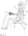
- a stacking vehicle 1 with a vehicle seat 2 arranged therein is shown in a side view.
- the vehicle seat 2 is composed of a backrest 3 and a seat plate 4 and a frame 5 and a neck support 6 together.
- Fig. 1 b is in a side view the in Fig. 1a shown vehicle seat 2 shown with inclined backrest.
- the frame 5 extends behind the backrest with a relative to the vertical slightly inclined backwards orientation to below the seat plate. 4
- the neck support 6 serves to support the neck 8 of a person operating the stacking vehicle 7.
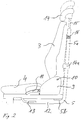
- Fig. 2 is shown in a side view of the vehicle seat in unclassified position according to an embodiment of the invention.
- the frame 5 consists of a first, substantially vertically extending section 5a, which is arranged behind the backrest 3 and a second section 5b connected to the first section 5a, the second section 5b below the seat plate 4 is oriented substantially horizontally.
- the first portion 5a is formed as a U-shaped tube such that it has two pipe sections which are aligned parallel to each other on the left and right sides with respect to the vehicle seat 2.
- the second section 5b consists of second tube-like sections, which are also aligned parallel to each other, and each having a not-shown here end-side end.
- the backrest 3 and the seat plate 4 are interconnected via pivotal connection elements 9 in such a way that the backrest 3 can pivot freely about an axis 10 extending substantially horizontally.
- an actuating lever 11 By means of an actuating lever 11, the backrest 3 can be tilted in a desired initial pivot position to obtain a high level of comfort even at normal position of the vehicle seat 2.
- the seat plate 4 can be horizontally displaced by second slide rails 12 mounted on the stacking vehicle 1 to a desired seating position of the driver 7 using the vehicle seat 2 depending on the leg length thereof in the stacking vehicle To obtain 1 arranged foot pedals.
- Such an initial displacement position of the seat plate 4 is performed by means of an operating lever 13.
- a neck support 14, which can also be designed as a headrest, is arranged on the top side on the first section 5a of the frame 5 by means of two rods 15 on the frame 5 and can preferably be adjusted in height by a path length of 170 mm.
- the height adjustment via an operating element 14 a, which is attached to the frame 5. From this operating element 14a from an electrical height adjustment or a mechanical height adjustment, for example by means of a cable frame mounted in the cable, done.
- All adjustment of the vehicle seat 2, so the longitudinal adjustment by a preferred length of 200 mm, the backrest adjustment and neck support adjustment are independently presettable.
- a roller 16 is disposed on the backrest back, which is on rails on a front side of the first portion 5a of the left and right side extending pipe sections unrolled.
- Fig. 3 is shown in a side view of the vehicle seat 2 in an inclined position according to the embodiment of the invention.
- the rollers 16 fixed to the backrest 3 roll downwards along the first section 5a of the frame and when the inclined backrest 3 is returned. This is indicated by the double arrow 17a.
- tilting of the backrest 3 takes place by pulling the lower region of the backrest 3 away by means of the seat plate 4 shifting forward and a vertical downward movement of the upper region of the backrest 3.
- the synchronous movement can be locked, initiated or terminated.
- Fig. 4 is a front view of a section of the vehicle seat 2 according to the embodiment of the invention shown.
- First slide rails 19 are on an underside of the seat plate 4 and slidably move on the second tube frame sections 5b of the frame 5.
- a plate-like formed member 20 carries the tube frame portions 5 b with the entire vehicle seat 2 and is formed at its left and right side edge portions 20 a and 20 b such that it includes the second slide rails 12 which are mounted on the stacking vehicle 1.
- the entire vehicle seat 2 including the member 20 is displaced from the left and right side second slide rails 12 by means of the operation member 13.
- Fig. 5a is a cross-sectional view taken along the line A- - -A Fig. 4 with a connecting element according to an embodiment of the invention.
- the connecting element is designed as a roller 16, which are connected by means of two sheet-like elements 16 a and 16 b with the rear wall of the backrest 3. These rollers 16 are connected via a in its side regions U-shaped wide frame 16c with the first portion 5a of the frame 5. The rollers can be moved within the U-shaped side portions of the further frame 16c with little play up and down.
- Fig. 5b is in a cross-sectional view taken along the line A- - -A Fig. 4 the connecting element according to another embodiment of the invention shown.
- the connecting element is not designed as a roller but as a sliding element 16d within the frame 16c, which is formed as a third slide rail in its side regions and is U-shaped.
- the further frame 16c is in turn connected to the first section 5a of the frame 5.
- the vehicle seat 2 can optionally also be equipped with a seat suspension in the vertical direction, a simple manual adjustment of the driver's weight, easy-to-read scales and - if desired - an automatic adjustment of the driver's weight with air suspension.
Landscapes
- Engineering & Computer Science (AREA)
- Aviation & Aerospace Engineering (AREA)
- Transportation (AREA)
- Mechanical Engineering (AREA)
- Seats For Vehicles (AREA)
- Forklifts And Lifting Vehicles (AREA)
Claims (6)
- Siège de véhicule pour des chariots élévateurs (1) qui comprennent un mât de levage, sur lequel est installé un moyen porteur de charge pouvant être déplacé vers le haut et vers le bas, le siège de véhicule (2) présentant une plaque de siège (4) et un dossier inclinable (3),
le siège de véhicule (2) présentant un cadre (5) pouvant être démonté du chariot élévateur, avec une première section (5a) s'étendant essentiellement à la verticale derrière le dossier (3) et une deuxième section (5b) s'étendant essentiellement à l'horizontale en dessous de la plaque de siège (4), un élément d'assemblage (16) agencé dans la partie supérieure du dossier (3) étant monté de façon déplaçable sur la première section (5a), le long de sa direction d'extension (17a), pour incliner le dossier (3), et
la deuxième section (5b) du cadre (5) présentant deux deuxièmes sections de cadre tubulaires (5b) s'étendant parallèlement l'une à l'autre, qui sont assemblées de façon coulissante avec des deuxièmes glissières (12) agencées sur le chariot élévateur (1), caractérisé en ce que
la plaque de siège (4) peut être déplacée dans le sens horizontal (17b) au moyen de premières glissières (19) assemblées avec la deuxième section (5b) en même temps que le mouvement d'inclinaison du dossier (3) et les premières glissières (19) sont agencées sur un côté inférieur de la plaque de siège (4) et peuvent être déplacées de façon coulissante sur les deuxièmes sections de cadre tubulaires (5b) du cadre (5), les deuxièmes sections de cadre tubulaires (5b) étant supportées, avec le siège de véhicule dans son ensemble, par un élément réalisé à la manière d'une plaque (20) qui est réalisé de telle sorte, sur ses zones de bord du côté gauche (20a) et du côté droit (20b), que les deuxièmes glissières (12) qui sont fixées sur le chariot élévateur sont englobées, l'élément semblable à une plaque (20) reposant sur les deuxièmes glissières (12) dans les zones de bord (20a, 20b) et les premières glissières (19) reposant sur l'élément semblable à une plaque (20) en dehors des zones de bord (20a, 20b). - Siège de véhicule selon la revendication 1,
caractérisé en ce que
la première section (5a) est réalisée en tant que première section de cadre tubulaire en forme de U (5a). - Siège de véhicule selon la revendication 2,
caractérisé en ce que
l'élément d'assemblage (16) est réalisé en tant que galets (16) pouvant rouler sur ou dans la première section de cadre tubulaire (5a) qui sont fixés sur un côté arrière du dossier (3). - Siège de véhicule selon la revendication 2,
caractérisé en ce que
l'élément d'assemblage est réalisé en tant qu'éléments coulissants (16d) pour coulisser à l'intérieur de troisièmes glissières agencées au niveau de la première section (5a). - Siège de véhicule selon l'une des revendications précédentes,
caractérisé en ce que
le dossier (3) est assemblé avec la plaque de siège (4) de façon pivotante par rapport à celle-ci au moyen de deux éléments d'assemblage pivotants (9) agencés des deux côtés du siège de véhicule (2). - Siège de véhicule selon la revendication 5,
caractérisé en ce que
les éléments d'assemblage pivotants (9) présentent un élément d'actionnement (11) pour régler une position de pivotement initiale individuelle du dossier (3) par rapport à la plaque de siège (4).
Applications Claiming Priority (2)
| Application Number | Priority Date | Filing Date | Title |
|---|---|---|---|
| DE102004014333A DE102004014333B4 (de) | 2004-03-22 | 2004-03-22 | Fahrzeugsitz für Stapelfahrzeuge |
| DE102004014333 | 2004-03-22 |
Publications (3)
| Publication Number | Publication Date |
|---|---|
| EP1580065A2 EP1580065A2 (fr) | 2005-09-28 |
| EP1580065A3 EP1580065A3 (fr) | 2009-11-04 |
| EP1580065B1 true EP1580065B1 (fr) | 2016-02-17 |
Family
ID=34854023
Family Applications (1)
| Application Number | Title | Priority Date | Filing Date |
|---|---|---|---|
| EP05101976.8A Expired - Lifetime EP1580065B1 (fr) | 2004-03-22 | 2005-03-14 | Siège de véhicule pour chariot élévateur |
Country Status (2)
| Country | Link |
|---|---|
| EP (1) | EP1580065B1 (fr) |
| DE (1) | DE102004014333B4 (fr) |
Cited By (1)
| Publication number | Priority date | Publication date | Assignee | Title |
|---|---|---|---|---|
| CN109849744A (zh) * | 2017-11-30 | 2019-06-07 | 格拉默公司 | 具有椅背悬架和座椅表面调节装置的车辆座椅 |
Families Citing this family (7)
| Publication number | Priority date | Publication date | Assignee | Title |
|---|---|---|---|---|
| DE102006051263B4 (de) * | 2006-10-31 | 2023-05-11 | Kion Warehouse Systems Gmbh | Fahrerplatz eines Flurförderzeugs |
| DE102007006246B4 (de) * | 2007-02-08 | 2009-12-03 | GM Global Technology Operations, Inc., Detroit | Personenkraftwagen mit Notsitz |
| FR3006254B1 (fr) * | 2013-06-03 | 2015-05-22 | Renault Sa | Banquette pour vehicule automobile |
| CN109070779B (zh) * | 2016-04-29 | 2021-11-05 | 恺博座椅机械部件有限公司 | 用于车辆座椅的扶手和车辆座椅 |
| DE102016011354A1 (de) | 2016-09-20 | 2018-03-22 | Liebherr-Werk Biberach Gmbh | Steuerstand für einen Kran, Bagger und dergleichen |
| WO2020234080A1 (fr) * | 2019-05-21 | 2020-11-26 | Adient Engineering and IP GmbH | Siège de véhicule |
| US12103444B2 (en) | 2021-01-20 | 2024-10-01 | Lear Corporation | Seat assembly |
Family Cites Families (13)
| Publication number | Priority date | Publication date | Assignee | Title |
|---|---|---|---|---|
| GB173772A (en) * | 1921-01-04 | 1922-12-14 | Albert Edwin Gell | Improvements in reclining adjustable chairs and seats |
| DE810177C (de) * | 1950-01-17 | 1951-08-06 | Bremshey & Co | Verstell- und ausziehbare Sitzeinrichtung |
| DE2041787C3 (de) * | 1970-08-22 | 1974-05-16 | Bremshey Ag, 5650 Solingen | Sitzeinrichtung, insbesondere für Schienenfahrzeuge |
| FR2285260A1 (fr) * | 1974-09-20 | 1976-04-16 | Sable Freres Int | Siege a dossier inclinable |
| DE3151259A1 (de) * | 1981-01-13 | 1982-08-05 | Stabilus Gmbh, 5400 Koblenz | Fahrzeugsitz |
| SE502714C2 (sv) * | 1991-11-18 | 1995-12-11 | Bt Ind Ab | Lyftfordon med inställbar förarstol för stapling av laster på hög höjd |
| DE9318743U1 (de) * | 1993-12-08 | 1994-05-11 | Biese, Gabriela-Maria, 35606 Solms | Sitzbank für Reisemobile, Transporter, etc. mit mindestens zwei Sitzteilen und mindestens zwei Rückenlehnenteilen sowie einer Einrichtung zur Aufnahme des oberen Punktes des Schultergurtes von mindestens einem Dreipunkt-Rückhaltesystem |
| US5584460A (en) * | 1995-03-31 | 1996-12-17 | Sears Manufacturing Co. | Adjustable seat apparatus and controls |
| JPH09202167A (ja) * | 1996-01-25 | 1997-08-05 | Nissan Motor Co Ltd | サスペンションシート |
| US6135412A (en) * | 1999-05-12 | 2000-10-24 | Buehler; Richard B. | Universal seat assembly for garden tractor |
| US6336619B1 (en) * | 2000-06-21 | 2002-01-08 | Michigan Seat Company | Adjustable seat platform |
| US6450578B1 (en) * | 2000-08-18 | 2002-09-17 | Michael Blake Taggett | Ergonomic chair |
| DE10064574C1 (de) * | 2000-12-22 | 2002-01-17 | Vogel Ind Gmbh | Fahrgastsitz für Personenbeförderungsfahrzeuge |
-
2004
- 2004-03-22 DE DE102004014333A patent/DE102004014333B4/de not_active Expired - Fee Related
-
2005
- 2005-03-14 EP EP05101976.8A patent/EP1580065B1/fr not_active Expired - Lifetime
Cited By (2)
| Publication number | Priority date | Publication date | Assignee | Title |
|---|---|---|---|---|
| CN109849744A (zh) * | 2017-11-30 | 2019-06-07 | 格拉默公司 | 具有椅背悬架和座椅表面调节装置的车辆座椅 |
| CN109849744B (zh) * | 2017-11-30 | 2021-07-06 | 格拉默公司 | 具有椅背悬架和座椅表面调节装置的车辆座椅 |
Also Published As
| Publication number | Publication date |
|---|---|
| DE102004014333A1 (de) | 2005-10-20 |
| EP1580065A2 (fr) | 2005-09-28 |
| DE102004014333B4 (de) | 2007-02-22 |
| EP1580065A3 (fr) | 2009-11-04 |
Similar Documents
| Publication | Publication Date | Title |
|---|---|---|
| EP1712410B1 (fr) | Siège de véhicule à dossier deformable | |
| DE60107287T2 (de) | In ein bett umwandelbarer sitz, insbesondere für ein flugzeug | |
| DE69004161T2 (de) | Fahrzeugsitz, insbesondere für Kraftfahrzeuge. | |
| EP1970245B1 (fr) | Siège passager pour véhicules sur rails | |
| DE60210583T2 (de) | Fahrzeugsitzanordnung mit einer nockengetriebenen, selbstpositionierenden kopfstütze | |
| DE60005510T2 (de) | Kontinuierliches, selbstverstellbares kopfstützensystem | |
| DE69803469T2 (de) | Fahrerstand für flurförderzeug mit in drei positionen verstellbarer sitzeinrichtung | |
| WO2003084811A1 (fr) | Siege, notamment siege pour passager de vol | |
| EP2746103B1 (fr) | Siège de véhicule utilitaire doté d'une partie de coulisseau transversal à double blocage | |
| DE102021003146B4 (de) | Sitzverstellvorrichtung für ein Fahrzeug | |
| DE112017003744T5 (de) | Verstellbare Kopfstütze | |
| DE112014001121T5 (de) | Räumlich kippender Rollstuhl mit Verwendung mehrerer Steuerwege | |
| EP1360086B1 (fr) | Siège, en particulier siège de véhicule, destiné de préférence à un passager d'avion | |
| DE102020116841A1 (de) | Drehende sitzbaugruppe | |
| EP1580065B1 (fr) | Siège de véhicule pour chariot élévateur | |
| EP4029727A1 (fr) | Panneau de commande pourvu de console d'assise pour une machine de construction | |
| EP1414670A1 (fr) | Siege | |
| WO2018215570A1 (fr) | Base de siège de véhicule, siège de véhicule et véhicule | |
| EP2548763B1 (fr) | Siège de véhicule doté d'une déformation de dossier | |
| DE102017122823A1 (de) | Zusammenklappbarer autositz zum erhöhen des frachtraums und der flexibilität | |
| EP1048510A2 (fr) | Banquette pour véhicules automobiles | |
| EP1777100B1 (fr) | Système de dossier | |
| DE202020104509U1 (de) | Sitz- und Liegemöbel | |
| DE102020216333B4 (de) | Sitzanordnung für ein Fahrzeug | |
| WO2022268523A1 (fr) | Siège de véhicule comportant un repose-pieds |
Legal Events
| Date | Code | Title | Description |
|---|---|---|---|
| PUAI | Public reference made under article 153(3) epc to a published international application that has entered the european phase |
Free format text: ORIGINAL CODE: 0009012 |
|
| AK | Designated contracting states |
Kind code of ref document: A2 Designated state(s): AT BE BG CH CY CZ DE DK EE ES FI FR GB GR HU IE IS IT LI LT LU MC NL PL PT RO SE SI SK TR |
|
| AX | Request for extension of the european patent |
Extension state: AL BA HR LV MK YU |
|
| 17P | Request for examination filed |
Effective date: 20060107 |
|
| RIC1 | Information provided on ipc code assigned before grant |
Ipc: B60N 2/22 20060101ALI20090508BHEP Ipc: B60N 2/07 20060101AFI20090508BHEP Ipc: B60N 2/48 20060101ALI20090508BHEP |
|
| PUAL | Search report despatched |
Free format text: ORIGINAL CODE: 0009013 |
|
| AK | Designated contracting states |
Kind code of ref document: A3 Designated state(s): AT BE BG CH CY CZ DE DK EE ES FI FR GB GR HU IE IS IT LI LT LU MC NL PL PT RO SE SI SK TR |
|
| AX | Request for extension of the european patent |
Extension state: AL BA HR LV MK YU |
|
| AKX | Designation fees paid |
Designated state(s): AT BE BG CH CY CZ DE DK EE ES FI FR GB GR HU IE IS IT LI LT LU MC NL PL PT RO SE SI SK TR |
|
| 17Q | First examination report despatched |
Effective date: 20100723 |
|
| GRAP | Despatch of communication of intention to grant a patent |
Free format text: ORIGINAL CODE: EPIDOSNIGR1 |
|
| INTG | Intention to grant announced |
Effective date: 20151006 |
|
| RIN1 | Information on inventor provided before grant (corrected) |
Inventor name: HALLER, NIKOLAUS Inventor name: MEILLER, HERMANN Inventor name: OTT, RICHARD |
|
| GRAS | Grant fee paid |
Free format text: ORIGINAL CODE: EPIDOSNIGR3 |
|
| GRAA | (expected) grant |
Free format text: ORIGINAL CODE: 0009210 |
|
| AK | Designated contracting states |
Kind code of ref document: B1 Designated state(s): AT BE BG CH CY CZ DE DK EE ES FI FR GB GR HU IE IS IT LI LT LU MC NL PL PT RO SE SI SK TR |
|
| REG | Reference to a national code |
Ref country code: GB Ref legal event code: FG4D Free format text: NOT ENGLISH |
|
| REG | Reference to a national code |
Ref country code: CH Ref legal event code: EP |
|
| REG | Reference to a national code |
Ref country code: IE Ref legal event code: FG4D Free format text: LANGUAGE OF EP DOCUMENT: GERMAN |
|
| REG | Reference to a national code |
Ref country code: AT Ref legal event code: REF Ref document number: 775479 Country of ref document: AT Kind code of ref document: T Effective date: 20160315 |
|
| REG | Reference to a national code |
Ref country code: FR Ref legal event code: PLFP Year of fee payment: 12 |
|
| REG | Reference to a national code |
Ref country code: DE Ref legal event code: R096 Ref document number: 502005015112 Country of ref document: DE |
|
| REG | Reference to a national code |
Ref country code: NL Ref legal event code: MP Effective date: 20160217 |
|
| REG | Reference to a national code |
Ref country code: LT Ref legal event code: MG4D |
|
| PG25 | Lapsed in a contracting state [announced via postgrant information from national office to epo] |
Ref country code: ES Free format text: LAPSE BECAUSE OF FAILURE TO SUBMIT A TRANSLATION OF THE DESCRIPTION OR TO PAY THE FEE WITHIN THE PRESCRIBED TIME-LIMIT Effective date: 20160217 Ref country code: FI Free format text: LAPSE BECAUSE OF FAILURE TO SUBMIT A TRANSLATION OF THE DESCRIPTION OR TO PAY THE FEE WITHIN THE PRESCRIBED TIME-LIMIT Effective date: 20160217 Ref country code: GR Free format text: LAPSE BECAUSE OF FAILURE TO SUBMIT A TRANSLATION OF THE DESCRIPTION OR TO PAY THE FEE WITHIN THE PRESCRIBED TIME-LIMIT Effective date: 20160518 |
|
| PG25 | Lapsed in a contracting state [announced via postgrant information from national office to epo] |
Ref country code: NL Free format text: LAPSE BECAUSE OF FAILURE TO SUBMIT A TRANSLATION OF THE DESCRIPTION OR TO PAY THE FEE WITHIN THE PRESCRIBED TIME-LIMIT Effective date: 20160217 Ref country code: BE Free format text: LAPSE BECAUSE OF NON-PAYMENT OF DUE FEES Effective date: 20160331 Ref country code: PT Free format text: LAPSE BECAUSE OF FAILURE TO SUBMIT A TRANSLATION OF THE DESCRIPTION OR TO PAY THE FEE WITHIN THE PRESCRIBED TIME-LIMIT Effective date: 20160617 Ref country code: LT Free format text: LAPSE BECAUSE OF FAILURE TO SUBMIT A TRANSLATION OF THE DESCRIPTION OR TO PAY THE FEE WITHIN THE PRESCRIBED TIME-LIMIT Effective date: 20160217 Ref country code: PL Free format text: LAPSE BECAUSE OF FAILURE TO SUBMIT A TRANSLATION OF THE DESCRIPTION OR TO PAY THE FEE WITHIN THE PRESCRIBED TIME-LIMIT Effective date: 20160217 Ref country code: SE Free format text: LAPSE BECAUSE OF FAILURE TO SUBMIT A TRANSLATION OF THE DESCRIPTION OR TO PAY THE FEE WITHIN THE PRESCRIBED TIME-LIMIT Effective date: 20160217 |
|
| PG25 | Lapsed in a contracting state [announced via postgrant information from national office to epo] |
Ref country code: DK Free format text: LAPSE BECAUSE OF FAILURE TO SUBMIT A TRANSLATION OF THE DESCRIPTION OR TO PAY THE FEE WITHIN THE PRESCRIBED TIME-LIMIT Effective date: 20160217 Ref country code: EE Free format text: LAPSE BECAUSE OF FAILURE TO SUBMIT A TRANSLATION OF THE DESCRIPTION OR TO PAY THE FEE WITHIN THE PRESCRIBED TIME-LIMIT Effective date: 20160217 |
|
| REG | Reference to a national code |
Ref country code: CH Ref legal event code: PL |
|
| REG | Reference to a national code |
Ref country code: DE Ref legal event code: R097 Ref document number: 502005015112 Country of ref document: DE |
|
| PG25 | Lapsed in a contracting state [announced via postgrant information from national office to epo] |
Ref country code: RO Free format text: LAPSE BECAUSE OF FAILURE TO SUBMIT A TRANSLATION OF THE DESCRIPTION OR TO PAY THE FEE WITHIN THE PRESCRIBED TIME-LIMIT Effective date: 20160217 Ref country code: SK Free format text: LAPSE BECAUSE OF FAILURE TO SUBMIT A TRANSLATION OF THE DESCRIPTION OR TO PAY THE FEE WITHIN THE PRESCRIBED TIME-LIMIT Effective date: 20160217 Ref country code: CZ Free format text: LAPSE BECAUSE OF FAILURE TO SUBMIT A TRANSLATION OF THE DESCRIPTION OR TO PAY THE FEE WITHIN THE PRESCRIBED TIME-LIMIT Effective date: 20160217 |
|
| PLBE | No opposition filed within time limit |
Free format text: ORIGINAL CODE: 0009261 |
|
| STAA | Information on the status of an ep patent application or granted ep patent |
Free format text: STATUS: NO OPPOSITION FILED WITHIN TIME LIMIT |
|
| REG | Reference to a national code |
Ref country code: IE Ref legal event code: MM4A |
|
| 26N | No opposition filed |
Effective date: 20161118 |
|
| PG25 | Lapsed in a contracting state [announced via postgrant information from national office to epo] |
Ref country code: IE Free format text: LAPSE BECAUSE OF NON-PAYMENT OF DUE FEES Effective date: 20160314 Ref country code: LI Free format text: LAPSE BECAUSE OF NON-PAYMENT OF DUE FEES Effective date: 20160331 Ref country code: CH Free format text: LAPSE BECAUSE OF NON-PAYMENT OF DUE FEES Effective date: 20160331 |
|
| PG25 | Lapsed in a contracting state [announced via postgrant information from national office to epo] |
Ref country code: BG Free format text: LAPSE BECAUSE OF FAILURE TO SUBMIT A TRANSLATION OF THE DESCRIPTION OR TO PAY THE FEE WITHIN THE PRESCRIBED TIME-LIMIT Effective date: 20160517 Ref country code: SI Free format text: LAPSE BECAUSE OF FAILURE TO SUBMIT A TRANSLATION OF THE DESCRIPTION OR TO PAY THE FEE WITHIN THE PRESCRIBED TIME-LIMIT Effective date: 20160217 |
|
| REG | Reference to a national code |
Ref country code: FR Ref legal event code: PLFP Year of fee payment: 13 |
|
| REG | Reference to a national code |
Ref country code: AT Ref legal event code: MM01 Ref document number: 775479 Country of ref document: AT Kind code of ref document: T Effective date: 20160314 |
|
| PG25 | Lapsed in a contracting state [announced via postgrant information from national office to epo] |
Ref country code: AT Free format text: LAPSE BECAUSE OF NON-PAYMENT OF DUE FEES Effective date: 20160314 |
|
| REG | Reference to a national code |
Ref country code: FR Ref legal event code: PLFP Year of fee payment: 14 |
|
| PG25 | Lapsed in a contracting state [announced via postgrant information from national office to epo] |
Ref country code: HU Free format text: LAPSE BECAUSE OF FAILURE TO SUBMIT A TRANSLATION OF THE DESCRIPTION OR TO PAY THE FEE WITHIN THE PRESCRIBED TIME-LIMIT; INVALID AB INITIO Effective date: 20050314 Ref country code: CY Free format text: LAPSE BECAUSE OF FAILURE TO SUBMIT A TRANSLATION OF THE DESCRIPTION OR TO PAY THE FEE WITHIN THE PRESCRIBED TIME-LIMIT Effective date: 20160217 |
|
| PG25 | Lapsed in a contracting state [announced via postgrant information from national office to epo] |
Ref country code: MC Free format text: LAPSE BECAUSE OF FAILURE TO SUBMIT A TRANSLATION OF THE DESCRIPTION OR TO PAY THE FEE WITHIN THE PRESCRIBED TIME-LIMIT Effective date: 20160217 Ref country code: IS Free format text: LAPSE BECAUSE OF FAILURE TO SUBMIT A TRANSLATION OF THE DESCRIPTION OR TO PAY THE FEE WITHIN THE PRESCRIBED TIME-LIMIT Effective date: 20160217 Ref country code: TR Free format text: LAPSE BECAUSE OF FAILURE TO SUBMIT A TRANSLATION OF THE DESCRIPTION OR TO PAY THE FEE WITHIN THE PRESCRIBED TIME-LIMIT Effective date: 20160217 Ref country code: LU Free format text: LAPSE BECAUSE OF NON-PAYMENT OF DUE FEES Effective date: 20160314 |
|
| PGFP | Annual fee paid to national office [announced via postgrant information from national office to epo] |
Ref country code: GB Payment date: 20190325 Year of fee payment: 15 Ref country code: FR Payment date: 20190326 Year of fee payment: 15 Ref country code: IT Payment date: 20190321 Year of fee payment: 15 |
|
| PG25 | Lapsed in a contracting state [announced via postgrant information from national office to epo] |
Ref country code: FR Free format text: LAPSE BECAUSE OF NON-PAYMENT OF DUE FEES Effective date: 20200331 |
|
| GBPC | Gb: european patent ceased through non-payment of renewal fee |
Effective date: 20200314 |
|
| PG25 | Lapsed in a contracting state [announced via postgrant information from national office to epo] |
Ref country code: GB Free format text: LAPSE BECAUSE OF NON-PAYMENT OF DUE FEES Effective date: 20200314 |
|
| PGFP | Annual fee paid to national office [announced via postgrant information from national office to epo] |
Ref country code: DE Payment date: 20210209 Year of fee payment: 17 |
|
| PG25 | Lapsed in a contracting state [announced via postgrant information from national office to epo] |
Ref country code: IT Free format text: LAPSE BECAUSE OF NON-PAYMENT OF DUE FEES Effective date: 20200314 |
|
| REG | Reference to a national code |
Ref country code: DE Ref legal event code: R119 Ref document number: 502005015112 Country of ref document: DE |
|
| PG25 | Lapsed in a contracting state [announced via postgrant information from national office to epo] |
Ref country code: DE Free format text: LAPSE BECAUSE OF NON-PAYMENT OF DUE FEES Effective date: 20221001 |