EP4454853A1 - Composant structurel - Google Patents
Composant structurel Download PDFInfo
- Publication number
- EP4454853A1 EP4454853A1 EP24171358.5A EP24171358A EP4454853A1 EP 4454853 A1 EP4454853 A1 EP 4454853A1 EP 24171358 A EP24171358 A EP 24171358A EP 4454853 A1 EP4454853 A1 EP 4454853A1
- Authority
- EP
- European Patent Office
- Prior art keywords
- structural component
- component according
- continuous fibers
- section
- hollow profile
- Prior art date
- Legal status (The legal status is an assumption and is not a legal conclusion. Google has not performed a legal analysis and makes no representation as to the accuracy of the status listed.)
- Withdrawn
Links
Images



Classifications
-
- B—PERFORMING OPERATIONS; TRANSPORTING
- B62—LAND VEHICLES FOR TRAVELLING OTHERWISE THAN ON RAILS
- B62D—MOTOR VEHICLES; TRAILERS
- B62D29/00—Superstructures, understructures, or sub-units thereof, characterised by the material thereof
- B62D29/04—Superstructures, understructures, or sub-units thereof, characterised by the material thereof predominantly of synthetic material
-
- B—PERFORMING OPERATIONS; TRANSPORTING
- B29—WORKING OF PLASTICS; WORKING OF SUBSTANCES IN A PLASTIC STATE IN GENERAL
- B29C—SHAPING OR JOINING OF PLASTICS; SHAPING OF MATERIAL IN A PLASTIC STATE, NOT OTHERWISE PROVIDED FOR; AFTER-TREATMENT OF THE SHAPED PRODUCTS, e.g. REPAIRING
- B29C45/00—Injection moulding, i.e. forcing the required volume of moulding material through a nozzle into a closed mould; Apparatus therefor
- B29C45/0005—Injection moulding, i.e. forcing the required volume of moulding material through a nozzle into a closed mould; Apparatus therefor using fibre reinforcements
-
- B—PERFORMING OPERATIONS; TRANSPORTING
- B29—WORKING OF PLASTICS; WORKING OF SUBSTANCES IN A PLASTIC STATE IN GENERAL
- B29C—SHAPING OR JOINING OF PLASTICS; SHAPING OF MATERIAL IN A PLASTIC STATE, NOT OTHERWISE PROVIDED FOR; AFTER-TREATMENT OF THE SHAPED PRODUCTS, e.g. REPAIRING
- B29C45/00—Injection moulding, i.e. forcing the required volume of moulding material through a nozzle into a closed mould; Apparatus therefor
- B29C45/14—Injection moulding, i.e. forcing the required volume of moulding material through a nozzle into a closed mould; Apparatus therefor incorporating preformed parts or layers, e.g. injection moulding around inserts or for coating articles
- B29C45/14778—Injection moulding, i.e. forcing the required volume of moulding material through a nozzle into a closed mould; Apparatus therefor incorporating preformed parts or layers, e.g. injection moulding around inserts or for coating articles the article consisting of a material with particular properties, e.g. porous, brittle
- B29C45/14786—Fibrous material or fibre containing material, e.g. fibre mats or fibre reinforced material
-
- B—PERFORMING OPERATIONS; TRANSPORTING
- B29—WORKING OF PLASTICS; WORKING OF SUBSTANCES IN A PLASTIC STATE IN GENERAL
- B29C—SHAPING OR JOINING OF PLASTICS; SHAPING OF MATERIAL IN A PLASTIC STATE, NOT OTHERWISE PROVIDED FOR; AFTER-TREATMENT OF THE SHAPED PRODUCTS, e.g. REPAIRING
- B29C45/00—Injection moulding, i.e. forcing the required volume of moulding material through a nozzle into a closed mould; Apparatus therefor
- B29C45/17—Component parts, details or accessories; Auxiliary operations
- B29C45/1703—Introducing an auxiliary fluid into the mould
- B29C45/1704—Introducing an auxiliary fluid into the mould the fluid being introduced into the interior of the injected material which is still in a molten state, e.g. for producing hollow articles
-
- B—PERFORMING OPERATIONS; TRANSPORTING
- B60—VEHICLES IN GENERAL
- B60J—WINDOWS, WINDSCREENS, NON-FIXED ROOFS, DOORS, OR SIMILAR DEVICES FOR VEHICLES; REMOVABLE EXTERNAL PROTECTIVE COVERINGS SPECIALLY ADAPTED FOR VEHICLES
- B60J5/00—Doors
- B60J5/04—Doors arranged at the vehicle sides
- B60J5/048—Doors arranged at the vehicle sides characterised by the material
- B60J5/0481—Doors arranged at the vehicle sides characterised by the material plastic
-
- B—PERFORMING OPERATIONS; TRANSPORTING
- B29—WORKING OF PLASTICS; WORKING OF SUBSTANCES IN A PLASTIC STATE IN GENERAL
- B29C—SHAPING OR JOINING OF PLASTICS; SHAPING OF MATERIAL IN A PLASTIC STATE, NOT OTHERWISE PROVIDED FOR; AFTER-TREATMENT OF THE SHAPED PRODUCTS, e.g. REPAIRING
- B29C45/00—Injection moulding, i.e. forcing the required volume of moulding material through a nozzle into a closed mould; Apparatus therefor
- B29C2045/0087—Injection moulding, i.e. forcing the required volume of moulding material through a nozzle into a closed mould; Apparatus therefor making hollow articles using a floating core movable in the mould cavity by fluid pressure and expelling molten excess material
-
- B—PERFORMING OPERATIONS; TRANSPORTING
- B29—WORKING OF PLASTICS; WORKING OF SUBSTANCES IN A PLASTIC STATE IN GENERAL
- B29C—SHAPING OR JOINING OF PLASTICS; SHAPING OF MATERIAL IN A PLASTIC STATE, NOT OTHERWISE PROVIDED FOR; AFTER-TREATMENT OF THE SHAPED PRODUCTS, e.g. REPAIRING
- B29C45/00—Injection moulding, i.e. forcing the required volume of moulding material through a nozzle into a closed mould; Apparatus therefor
- B29C45/17—Component parts, details or accessories; Auxiliary operations
- B29C45/1703—Introducing an auxiliary fluid into the mould
- B29C45/1704—Introducing an auxiliary fluid into the mould the fluid being introduced into the interior of the injected material which is still in a molten state, e.g. for producing hollow articles
- B29C45/1706—Introducing an auxiliary fluid into the mould the fluid being introduced into the interior of the injected material which is still in a molten state, e.g. for producing hollow articles using particular fluids or fluid generating substances
- B29C2045/1707—Introducing an auxiliary fluid into the mould the fluid being introduced into the interior of the injected material which is still in a molten state, e.g. for producing hollow articles using particular fluids or fluid generating substances using a liquid, e.g. water
-
- B—PERFORMING OPERATIONS; TRANSPORTING
- B29—WORKING OF PLASTICS; WORKING OF SUBSTANCES IN A PLASTIC STATE IN GENERAL
- B29C—SHAPING OR JOINING OF PLASTICS; SHAPING OF MATERIAL IN A PLASTIC STATE, NOT OTHERWISE PROVIDED FOR; AFTER-TREATMENT OF THE SHAPED PRODUCTS, e.g. REPAIRING
- B29C45/00—Injection moulding, i.e. forcing the required volume of moulding material through a nozzle into a closed mould; Apparatus therefor
- B29C45/17—Component parts, details or accessories; Auxiliary operations
- B29C45/1703—Introducing an auxiliary fluid into the mould
- B29C45/1704—Introducing an auxiliary fluid into the mould the fluid being introduced into the interior of the injected material which is still in a molten state, e.g. for producing hollow articles
- B29C2045/1723—Introducing an auxiliary fluid into the mould the fluid being introduced into the interior of the injected material which is still in a molten state, e.g. for producing hollow articles using fibre reinforcements
-
- B—PERFORMING OPERATIONS; TRANSPORTING
- B29—WORKING OF PLASTICS; WORKING OF SUBSTANCES IN A PLASTIC STATE IN GENERAL
- B29K—INDEXING SCHEME ASSOCIATED WITH SUBCLASSES B29B, B29C OR B29D, RELATING TO MOULDING MATERIALS OR TO MATERIALS FOR MOULDS, REINFORCEMENTS, FILLERS OR PREFORMED PARTS, e.g. INSERTS
- B29K2105/00—Condition, form or state of moulded material or of the material to be shaped
- B29K2105/06—Condition, form or state of moulded material or of the material to be shaped containing reinforcements, fillers or inserts
- B29K2105/08—Condition, form or state of moulded material or of the material to be shaped containing reinforcements, fillers or inserts of continuous length, e.g. cords, rovings, mats, fabrics, strands or yarns
-
- B—PERFORMING OPERATIONS; TRANSPORTING
- B29—WORKING OF PLASTICS; WORKING OF SUBSTANCES IN A PLASTIC STATE IN GENERAL
- B29L—INDEXING SCHEME ASSOCIATED WITH SUBCLASS B29C, RELATING TO PARTICULAR ARTICLES
- B29L2022/00—Hollow articles
-
- B—PERFORMING OPERATIONS; TRANSPORTING
- B29—WORKING OF PLASTICS; WORKING OF SUBSTANCES IN A PLASTIC STATE IN GENERAL
- B29L—INDEXING SCHEME ASSOCIATED WITH SUBCLASS B29C, RELATING TO PARTICULAR ARTICLES
- B29L2031/00—Other particular articles
- B29L2031/30—Vehicles, e.g. ships or aircraft, or body parts thereof
-
- B—PERFORMING OPERATIONS; TRANSPORTING
- B60—VEHICLES IN GENERAL
- B60J—WINDOWS, WINDSCREENS, NON-FIXED ROOFS, DOORS, OR SIMILAR DEVICES FOR VEHICLES; REMOVABLE EXTERNAL PROTECTIVE COVERINGS SPECIALLY ADAPTED FOR VEHICLES
- B60J5/00—Doors
- B60J5/10—Doors arranged at the vehicle rear
- B60J5/101—Doors arranged at the vehicle rear for non-load transporting vehicles, i.e. family cars including vans
- B60J5/107—Doors arranged at the vehicle rear for non-load transporting vehicles, i.e. family cars including vans constructional details, e.g. about door frame, panels, materials used, reinforcements
Definitions
- the invention relates to a structural component, in particular a structural component for use in a motor vehicle, for example in a vehicle body.
- Structural components are used in many areas and are regularly used to absorb and transmit mechanical forces. They can also be used to connect other components to one another. In many cases, attempts are made to provide a structural component with high rigidity and low weight at the same time. This is particularly important in the field of lightweight construction, which is increasingly proving to be advantageous and is being used more and more frequently in many areas of technology.
- Vehicles especially motor vehicles, can also be made lighter and more stable by using such structural components without having to sacrifice comfort and safety.
- structural components helps, among other things, to reduce CO2 emissions.
- structural components are used to protect components and assemblies.
- Flat, fiber-reinforced structural components can be used on the underside of a vehicle, for example, and then serve as underbody protection.
- the publication DE 10 2017 110 906 A1 describes a structural component that is designed in particular for use in a vehicle body.
- the structural component has a first structural element that at least partially surrounds a spatial region, so that a cavity is formed in the interior of the first structural element.
- This first structural element has a surface region that delimits this cavity and a second structural element.
- a reinforcing element which serves to mechanically reinforce the first structural element.
- Fluid injection technology is an umbrella term for processes in which cavities are created by injecting a fluid. Fluid injection technology can be combined with injection molding, an extrusion process or any other suitable process. FIT is used in particular in connection with plastics, especially polymer materials. In addition to the usual design features of plastic parts, this technology or process can be used to produce hollow profiles in the components, and this can be done at low cost. Due to the hollow geometry of the components, FIT components have greater rigidity, while at the same time being lightweight and cost-effective to manufacture.
- Continuous fiber composites are materials in which continuous fiber reinforcements are combined with a matrix material. The properties are combined, resulting in a material with high stiffness and strength along the direction of the fibers.
- the FIT method can only be used to process plastics or polymers with or without particles, short or long fiber reinforcement, but not with continuous fiber reinforcement. These materials have lower stiffness and strength compared to composites with continuous fibers if the components, ie the reinforcement and the matrix, are the same. Although the hollow profile increases the component stiffness many times over, the extreme stresses are reduced under the influence of mechanical loads. Layer of the material is subjected to the highest load. This is the weak point of the material itself. In the FIT process, unreinforced, short-fiber reinforced, ie up to 3 mm fiber length, or long-fiber reinforced, ie from 3 mm fiber length, can be used. A combination with continuous fibers has not yet been used.
- the structural component presented is intended, for example, for installation or use in a motor vehicle.
- This structural component is manufactured using a fluid injection technique and has at least a first section in which a hollow profile is provided and at least a second section which is reinforced with continuous fibers.
- the structural component can be constructed such that at least one first section and at least one second section are arranged relative to one another such that the at least one first section is at least partially surrounded by the at least one second section.
- the structural component can, for example, be designed as a hollow body which comprises an inner cut-out cavity and a wall, wherein the cut-out cavity defines the hollow profile and the wall has the second section with the continuous fibers.
- the hollow profile can, for example, be created by a water-propelled projectile.
- the continuous fibers can, for example, run parallel and/or diagonally to a longitudinal axis of the hollow profile in an area on the outside of the wall.
- the structural component presented can be made of a thermoplastic or thermosetting plastic with or without reinforcement.
- Continuous fibers can also be used with or without matrix material.
- the continuous fibers can be incorporated in the fluid injection step or after this step.
- the present invention which is embodied by the structural component presented, thus relates to the reinforcement of polymer or plastic components with a hollow profile or hollow cross-section with continuous fibers.
- E-FIT is an acronym for the term Endless fiber composite and Fluid Injection Technology.
- E-FIT components manufactured using this E-FIT process have the advantage of having higher mechanical performance due to both the continuous fiber composite material used and the geometric characteristics of the FIT components. For this reason, E-FIT components have extremely high specific stiffness and strength, resulting in lightweight, low-cost designs. Such E-FIT components can be used in the automotive, aviation and electric bicycle sectors. are used, but are not limited to these areas, but can be used in a variety of ways.
- the components manufactured in this way have a higher mechanical performance, particularly in terms of stiffness and strength, due to the geometric characteristics of the hollow profiles. Reinforcements with continuous fibers have a higher mechanical performance due to the material or the material itself.
- FIT fluid injection technology
- Any polymer or plastic produced in a conventional plastic manufacturing process such as injection molding, compression molding, can be used for E-FIT, including thermoplastics and thermosetting plastics, with or without reinforcement. Short fibers or long fibers can be used for reinforcement.
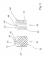
- Continuous fibers can be fibers with or without matrix material. Furthermore, fibers can be unidirectional, layered (layup) or multi-layered in the designed Orientation, laminate, woven or braided etc. It is referred to Figure 3 referred to.
- All kinds of materials can be used for continuous fibers, including glass, carbon, synthetic aramid fiber, natural materials, basalt fiber, etc.
- Continuous fibers can be incorporated during the FIT process. Alternatively, continuous fibers can be incorporated after the FIT process, which requires an additional step.
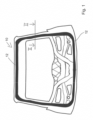
- Figure 1 shows a structural component 10 of a motor vehicle, wherein several structural segments 12 are incorporated into this structural component 10. These structural segments 12, which consist of a plastic material, are manufactured using an E-FIT process. This can be done in a one-step process.
- Figure 2 shows a section along the line II-II in Figure 1 .
- a hollow profile 14 can be seen in a first section 13.
- a profiling 16 is provided in two second sections 18 with continuous fibers.
- Figure 3 shows a first structural component 30 and a second structural component 40.
- the two structural components 30, 40 are each constructed as hollow bodies with a cut-out cavity 35 or 45 and a wall 37 or 47 surrounding this cavity 35 or 45 and have on their outer surfaces or in the region of their outer surfaces on the wall 37 or 47 areas or second sections 32 or 42 which are reinforced with continuous fibers 33 or 43.
- the section 32 has continuous fibers 33 that are aligned diagonally, for example at an angle of 45°, with respect to a longitudinal axis 34 of the structural component 30 and overlapping or crossing each other. This orientation is particularly suitable for torsional loading, as shown by arrow 36.
- the continuous fibers 43 are aligned parallel to the longitudinal axis 44 of the structural component 40. This is particularly suitable for a bending load, as shown by arrow 46.
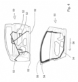
- Figure 4 shows another structural component 50, in this case a front side door, in two representations.
- the representation above illustrates a component design with six injection points 52 and a cascade for a cored U-profile.
- the representation shows a circular interrupted channel 54.
- An arrow 56 shows the direction of the long fiber orientation.
- the illustration shows the cold runner connection to surfaces of the structural component 50 and the partial filling via a cold runner 58. Complete filling of the surfaces takes place via the cold runner 58.
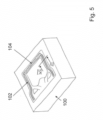
- Figure 5 shows an opened tool 100 with a first continuous fiber insert 102 and a second continuous fiber insert 104. After closing the tool 100, plastic reinforced with long or short fibers is introduced and the hollow profile is produced by means of a fluid injection technique.
- Figure 6 shows a section along the line VI-VI in Figure 5
- the illustration shows a structural component 150 with a hollow profile 152, a first section 154 made of long or short fiber reinforced plastic and two continuous fiber inserts 156 which form the second section.
- Figure 7 shows in a flow chart a possible procedure for producing a structural component of the type described here using injection molding as an example.
- a tool is opened and a component is removed if one is present. Then, in a step 202, continuous fiber inserts are positioned. In a step 204, the tool is then closed. Then, in a step 206, a polymer reinforced with short or long fibers is injected and a cavity in the tool is filled. In a step 208, a fluid is injected and the hollow profile is formed. The workpiece, the later structural component, then cools down in a step 210. Once this has been done, the tool is opened in a step 212 and the structural component is removed in a step 214.
- Figure 8 shows in a further flow chart another possible procedure for producing another structural component of the type described here using the example of extrusion.
- a tool is opened and a component is removed if one is present. Then, in a step 302, continuous fiber inserts are positioned. Then, in a step 304, a polymer reinforced with short or long fibers is deposited. In a step 306, the tool is closed and a cavity in the tool is filled. In a step 308, a fluid is injected and a hollow profile is formed. The workpiece, the later structural component, then cools down in a step 310. Once this has been done, the tool is opened in a step 312 and the structural component is removed in a step 314.
Landscapes
- Engineering & Computer Science (AREA)
- Mechanical Engineering (AREA)
- Manufacturing & Machinery (AREA)
- Architecture (AREA)
- Structural Engineering (AREA)
- Chemical & Material Sciences (AREA)
- Combustion & Propulsion (AREA)
- Transportation (AREA)
- Moulding By Coating Moulds (AREA)
- Laminated Bodies (AREA)
- Body Structure For Vehicles (AREA)
Applications Claiming Priority (1)
| Application Number | Priority Date | Filing Date | Title |
|---|---|---|---|
| DE202023102167.0U DE202023102167U1 (de) | 2023-04-24 | 2023-04-24 | Strukturbauteil |
Publications (1)
| Publication Number | Publication Date |
|---|---|
| EP4454853A1 true EP4454853A1 (fr) | 2024-10-30 |
Family
ID=86499042
Family Applications (1)
| Application Number | Title | Priority Date | Filing Date |
|---|---|---|---|
| EP24171358.5A Withdrawn EP4454853A1 (fr) | 2023-04-24 | 2024-04-19 | Composant structurel |
Country Status (3)
| Country | Link |
|---|---|
| US (1) | US20240351254A1 (fr) |
| EP (1) | EP4454853A1 (fr) |
| DE (1) | DE202023102167U1 (fr) |
Families Citing this family (2)
| Publication number | Priority date | Publication date | Assignee | Title |
|---|---|---|---|---|
| DE202022107086U1 (de) * | 2022-12-20 | 2023-01-26 | Weber Fibertech Gmbh | Lenkeranordnung |
| DE102024118543A1 (de) | 2024-07-01 | 2026-01-08 | Dr. Ing. H.C. F. Porsche Aktiengesellschaft | Kraftfahrzeug mit Aussteifungsstruktur |
Citations (10)
| Publication number | Priority date | Publication date | Assignee | Title |
|---|---|---|---|---|
| DE19747021A1 (de) * | 1997-10-24 | 1999-04-29 | Ver Foerderung Inst Kunststoff | Verfahren zum Spritzgießen endlosfaserverstärkter Hohlkörper |
| EP1581380B1 (fr) * | 2002-09-15 | 2007-03-07 | Weber Technology AG | Element structurel en matiere thermoplastique renforcee par des fibres |
| DE102008017377A1 (de) * | 2008-04-05 | 2009-10-08 | Röchling Technische Teile KG | Leichtbauteil sowie Verfahren zur Herstellung hierfür |
| DE102008046602A1 (de) * | 2008-09-10 | 2010-03-11 | Daimler Ag | Verfahren zur Herstellung eines Bauteils mit einem Hohlprofil |
| DE102012004168A1 (de) * | 2011-03-04 | 2012-09-06 | Heiner Becker | Verfahren zum Spritzgießen von Hohlkörpern mit Endlosfaser-Verstärkungselementen |
| DE102013215375A1 (de) * | 2013-08-05 | 2015-02-05 | Bayerische Motoren Werke Aktiengesellschaft | Verfahren für die Herstellung eines wenigstens abschnittsweise hohlen Strukturbauteils eines Fahrzeugs |
| DE102017110906A1 (de) | 2017-05-18 | 2018-11-22 | Hbpo Gmbh | Strukturbauteil |
| DE102019209326A1 (de) * | 2019-06-27 | 2020-12-31 | Volkswagen Aktiengesellschaft | Fahrzeug-Heckklappe sowie Verfahren zur Herstellung einer solchen Fahrzeug-Heckklappe |
| EP3218170B1 (fr) * | 2014-11-11 | 2021-08-25 | Bayerische Motoren Werke Aktiengesellschaft | Élément structural en matériau renforcé par des fibres et son procédé de fabrication |
| DE102020128526A1 (de) * | 2020-10-29 | 2022-05-05 | Kautex Textron Gmbh & Co. Kg | Batterieschale, Traktionsbatterie, Kraftfahrzeug, Werkzeug zum Herstellen einer monolithischen Batterieschale und Verfahren zum Herstellen einer monolithischen Batterieschale |
Family Cites Families (2)
| Publication number | Priority date | Publication date | Assignee | Title |
|---|---|---|---|---|
| JPH07329199A (ja) * | 1994-06-06 | 1995-12-19 | Nippon Oil Co Ltd | 繊維強化複合材円筒状成形物 |
| US20120244301A1 (en) * | 2011-03-22 | 2012-09-27 | Basf Se | Component with a hollow body that can be subjected to internal pressure |
-
2023
- 2023-04-24 DE DE202023102167.0U patent/DE202023102167U1/de active Active
-
2024
- 2024-04-19 EP EP24171358.5A patent/EP4454853A1/fr not_active Withdrawn
- 2024-04-23 US US18/643,232 patent/US20240351254A1/en active Pending
Patent Citations (10)
| Publication number | Priority date | Publication date | Assignee | Title |
|---|---|---|---|---|
| DE19747021A1 (de) * | 1997-10-24 | 1999-04-29 | Ver Foerderung Inst Kunststoff | Verfahren zum Spritzgießen endlosfaserverstärkter Hohlkörper |
| EP1581380B1 (fr) * | 2002-09-15 | 2007-03-07 | Weber Technology AG | Element structurel en matiere thermoplastique renforcee par des fibres |
| DE102008017377A1 (de) * | 2008-04-05 | 2009-10-08 | Röchling Technische Teile KG | Leichtbauteil sowie Verfahren zur Herstellung hierfür |
| DE102008046602A1 (de) * | 2008-09-10 | 2010-03-11 | Daimler Ag | Verfahren zur Herstellung eines Bauteils mit einem Hohlprofil |
| DE102012004168A1 (de) * | 2011-03-04 | 2012-09-06 | Heiner Becker | Verfahren zum Spritzgießen von Hohlkörpern mit Endlosfaser-Verstärkungselementen |
| DE102013215375A1 (de) * | 2013-08-05 | 2015-02-05 | Bayerische Motoren Werke Aktiengesellschaft | Verfahren für die Herstellung eines wenigstens abschnittsweise hohlen Strukturbauteils eines Fahrzeugs |
| EP3218170B1 (fr) * | 2014-11-11 | 2021-08-25 | Bayerische Motoren Werke Aktiengesellschaft | Élément structural en matériau renforcé par des fibres et son procédé de fabrication |
| DE102017110906A1 (de) | 2017-05-18 | 2018-11-22 | Hbpo Gmbh | Strukturbauteil |
| DE102019209326A1 (de) * | 2019-06-27 | 2020-12-31 | Volkswagen Aktiengesellschaft | Fahrzeug-Heckklappe sowie Verfahren zur Herstellung einer solchen Fahrzeug-Heckklappe |
| DE102020128526A1 (de) * | 2020-10-29 | 2022-05-05 | Kautex Textron Gmbh & Co. Kg | Batterieschale, Traktionsbatterie, Kraftfahrzeug, Werkzeug zum Herstellen einer monolithischen Batterieschale und Verfahren zum Herstellen einer monolithischen Batterieschale |
Non-Patent Citations (2)
| Title |
|---|
| CARL HANSER VERLAG ET AL: "Hohlkörperverbundstrukturen im Minutentakt - FIT-Hybrid", 30 March 2011 (2011-03-30), XP055145802, Retrieved from the Internet <URL:https://www.kunststoffe.de/_storage/asset/536825/storage/master/file/5966470/download/Hohlkörperverbundstrukturen im Minutentakt.pdf> [retrieved on 20141010] * |
| WESTPHAL FRIEDRICH ET AL: "Serienmässig leichte Kunststofftür", KUNSTSTOFFE 11/2018, 6 November 2018 (2018-11-06), pages 86 - 89, XP093204521, Retrieved from the Internet <URL:https://res.cloudinary.com/sternwald-systems/raw/upload/v1/hugoprd/ARTIKEL_ATTACH/00241CE0_79249FA48EAA/1be045adb2a80edd36cad97c0a341ab82321cff0/KU_2018_11_Serienmaessig-leichte-Kunststofftuer.pdf> * |
Also Published As
| Publication number | Publication date |
|---|---|
| DE202023102167U1 (de) | 2023-05-04 |
| US20240351254A1 (en) | 2024-10-24 |
Similar Documents
| Publication | Publication Date | Title |
|---|---|---|
| DE102010003497B4 (de) | Verfahren zur Herstellung eines Aufprallschutzelementes | |
| EP2759423B1 (fr) | Bras oscillant transversal en plastique renforcé en fibres pour une suspension de roue d'un véhicule | |
| DE102018125169B4 (de) | Faserverstärkter stossfängerträger aus verbundwerkstoffen und stauchelementen | |
| EP4454853A1 (fr) | Composant structurel | |
| EP3178634B1 (fr) | Procédé de fabrication d'un composant en matériau hybride | |
| EP3165430B1 (fr) | Procédé de fabrication d'une structure de liaison comprenant au moins deux composants profilés, et structure de liaison et carrosserie | |
| DE102011108156A1 (de) | Verbindungsstruktur für einen Kraftwagen und Verfahren zu deren Herstellung | |
| DE102008061463A1 (de) | Lasteinleitungseinrichtung | |
| DE102012018801B4 (de) | Beplankungsbauteil für einen Kraftwagen und Verfahren zum Herstellen eines Beplankungsbauteils | |
| DE102010053732A1 (de) | Drehstabfeder oder Wankstabilisator für ein Kraftfahrzeug sowie Verfahren zu deren Herstellung | |
| EP1052164A1 (fr) | Groupe de paroi pour véhicule automobile | |
| EP2626218B1 (fr) | Procédé de fabrication d'une jante à base de matière première composite en fibres et jante pour un véhicule automobile | |
| EP3165428B1 (fr) | Structure de liaison pour carrosserie de véhicule, son procédé de fabrication et carrosserie de véhicule comprenant au moins une structure de liaison | |
| DE102012216727A1 (de) | Funktionsoptimiertes Faserverbundbauteil und Verfahren zu dessen Herstellung | |
| EP3188885B1 (fr) | Procédé de fabrication d'une pièce multi-couche de matière composite avec une structure renforcée intégrée | |
| DE102008029518B4 (de) | Verfahren zur Herstellung von Faserverbundbauteilen und Faserverbundbauteile | |
| DE102008007545A1 (de) | Lasttragendes und schadenstolerantes Laminatflugzeugfenster | |
| DE102011121639A1 (de) | Rotationssymmetrisches Strukturelement in Gitterkonstruktion und Verfahren zu dessen Herstellung | |
| EP3165431B1 (fr) | Structure de liaison comprenant au moins un composant en corps creux à double paroi, procédé de fabrication et carrosserie de véhicule | |
| DE10060042A1 (de) | Faserverstärktes Verbundbauteil aus Metall- und Kunststoffteilen und Verfahren zu dessen Herstellung | |
| DE102011109700A1 (de) | Faserverstärktes Kunststoffverbundbauteil, Faser-Matrix-Halbzeug und Herstellungsverfahren | |
| DE102011003747A1 (de) | Faserverstärktes Bauteil und Verfahren zur Herstellung eines faserverstärkten Bauteils | |
| EP1997716B1 (fr) | Profilé en matière composite fibreuse et cadre de vitre de véhicule automobile | |
| DE102014208835A1 (de) | Verfahren zur Herstellung eines Kunststoffbauteils | |
| EP3122543B1 (fr) | Pièce en matériau composite renforcé par des fibres et son procédé de fabrication |
Legal Events
| Date | Code | Title | Description |
|---|---|---|---|
| PUAI | Public reference made under article 153(3) epc to a published international application that has entered the european phase |
Free format text: ORIGINAL CODE: 0009012 |
|
| STAA | Information on the status of an ep patent application or granted ep patent |
Free format text: STATUS: THE APPLICATION HAS BEEN PUBLISHED |
|
| AK | Designated contracting states |
Kind code of ref document: A1 Designated state(s): AL AT BE BG CH CY CZ DE DK EE ES FI FR GB GR HR HU IE IS IT LI LT LU LV MC ME MK MT NL NO PL PT RO RS SE SI SK SM TR |
|
| STAA | Information on the status of an ep patent application or granted ep patent |
Free format text: STATUS: THE APPLICATION IS DEEMED TO BE WITHDRAWN |
|
| 18D | Application deemed to be withdrawn |
Effective date: 20250501 |