EP1586478A1 - Embout pour tubulure de remplissage en carburant d'un véhicule - Google Patents
Embout pour tubulure de remplissage en carburant d'un véhicule Download PDFInfo
- Publication number
- EP1586478A1 EP1586478A1 EP05290762A EP05290762A EP1586478A1 EP 1586478 A1 EP1586478 A1 EP 1586478A1 EP 05290762 A EP05290762 A EP 05290762A EP 05290762 A EP05290762 A EP 05290762A EP 1586478 A1 EP1586478 A1 EP 1586478A1
- Authority
- EP
- European Patent Office
- Prior art keywords
- end piece
- shutter
- latch
- spout
- piece according
- Prior art date
- Legal status (The legal status is an assumption and is not a legal conclusion. Google has not performed a legal analysis and makes no representation as to the accuracy of the status listed.)
- Granted
Links
- 239000000945 filler Substances 0.000 title claims abstract description 13
- 239000000446 fuel Substances 0.000 title claims abstract description 11
- 239000002184 metal Substances 0.000 claims description 8
- 239000007788 liquid Substances 0.000 claims description 5
- 210000002445 nipple Anatomy 0.000 description 4
- 239000000463 material Substances 0.000 description 3
- 239000011324 bead Substances 0.000 description 2
- 239000002991 molded plastic Substances 0.000 description 2
- XLYOFNOQVPJJNP-UHFFFAOYSA-N water Substances O XLYOFNOQVPJJNP-UHFFFAOYSA-N 0.000 description 2
- 238000005452 bending Methods 0.000 description 1
- 238000004140 cleaning Methods 0.000 description 1
- 230000000694 effects Effects 0.000 description 1
- 239000012530 fluid Substances 0.000 description 1
- 239000002828 fuel tank Substances 0.000 description 1
- 238000004519 manufacturing process Methods 0.000 description 1
- 230000002093 peripheral effect Effects 0.000 description 1
- 238000000926 separation method Methods 0.000 description 1
- 238000005406 washing Methods 0.000 description 1
- 238000003466 welding Methods 0.000 description 1
Images


Classifications
-
- B—PERFORMING OPERATIONS; TRANSPORTING
- B60—VEHICLES IN GENERAL
- B60K—ARRANGEMENT OR MOUNTING OF PROPULSION UNITS OR OF TRANSMISSIONS IN VEHICLES; ARRANGEMENT OR MOUNTING OF PLURAL DIVERSE PRIME-MOVERS IN VEHICLES; AUXILIARY DRIVES FOR VEHICLES; INSTRUMENTATION OR DASHBOARDS FOR VEHICLES; ARRANGEMENTS IN CONNECTION WITH COOLING, AIR INTAKE, GAS EXHAUST OR FUEL SUPPLY OF PROPULSION UNITS IN VEHICLES
- B60K15/00—Arrangement in connection with fuel supply of combustion engines or other fuel consuming energy converters, e.g. fuel cells; Mounting or construction of fuel tanks
- B60K15/03—Fuel tanks
- B60K15/04—Tank inlets
-
- B—PERFORMING OPERATIONS; TRANSPORTING
- B60—VEHICLES IN GENERAL
- B60K—ARRANGEMENT OR MOUNTING OF PROPULSION UNITS OR OF TRANSMISSIONS IN VEHICLES; ARRANGEMENT OR MOUNTING OF PLURAL DIVERSE PRIME-MOVERS IN VEHICLES; AUXILIARY DRIVES FOR VEHICLES; INSTRUMENTATION OR DASHBOARDS FOR VEHICLES; ARRANGEMENTS IN CONNECTION WITH COOLING, AIR INTAKE, GAS EXHAUST OR FUEL SUPPLY OF PROPULSION UNITS IN VEHICLES
- B60K15/00—Arrangement in connection with fuel supply of combustion engines or other fuel consuming energy converters, e.g. fuel cells; Mounting or construction of fuel tanks
- B60K15/03—Fuel tanks
- B60K15/04—Tank inlets
- B60K2015/0458—Details of the tank inlet
- B60K2015/0483—Means to inhibit the introduction of too small or too big filler nozzles
Definitions
- the invention relates to the filling of vehicles with fuel, and more particularly to the end pieces with which vehicles are provided to cooperate with the spout at the end of a fuel supply nozzle.
- the outer diameter of the spout of such a nozzle in practice has a value which depends on the fuel distributed.
- the spout of a nozzle belonging to a pump supplying diesel or leaded petrol has a greater diameter than the spout of a nozzle belonging to a pump supplying lead-free petrol.
- the invention is directed to providing such an end piece which is particularly simple, convenient and economic, with respect to both manufacture and use.
- an end piece for a fuel filler pipe of a vehicle provided for allowing the passage to said pipe of a supply spout exclusively if the outer diameter of said spout is at least equal to a predetermined threshold, the end piece being characterized in that it comprises a protection assembly comprising:
- a spout of greater diameter than the predetermined threshold for example a spout for diesel, is thus capable, when it is thrust into the protection assembly, of driving each of the two latches to the withdrawn position, such that the shutter can then be driven to the freeing position.
- a spout of smaller diameter than the predetermined threshold for example a spout for lead-free petrol, will only be able to act on one of them at a time, such that there will always remain one of the latches to lock the shutter in the obturating position, so preventing access to the filler pipe.
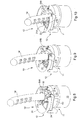
- the end piece 10 illustrated in the drawings comprises an obturating assembly 11 and a protection assembly 12.
- the assembly 11 is adapted for mounting on an end of a pipe 13 ( Figures 5 to 10) for filling a vehicle fuel tank (not shown) with fuel, here diesel, the tank being disposed at the other end of the pipe 13 (only a portion of the pipe 13 situated in the neighborhood of the assembly 11 is shown).
- the assembly 11 is adapted for being fixed from behind (the side which is seen downwards in Figures 3 to 10) to pipe 13.
- Assembly 12 is fixed to the front (the side which is seen upwards)
- Assembly 11 and assembly 12 are adapted to securely obdurate the pipe 13 in an operating configuration and, from the operating configuration, by a simple thrusting movement, to allow the passage of the spout 14 of a supply nozzle for an appropriate fuel, the fuel being diesel here, through assembly 12 and then assembly 11, in order to reach the filling position illustrated in Figure 10, in which the distal end of the spout 14 communicates with the interior space of the pipe 13.
- the protection assembly 12 will now be described in detail.
- this assembly comprises a cover 20, latches 21A and 21B, a spring 22, a shutter 23 and a cup 24.
- latches 21A and 21B and the spring 22 are of molded plastics material.
- the cover 20 comprises a plane wall 25 of circular outline in which there is provided, in an eccentric position, an aperture 26 for introduction of the spout 14.
- an aperture 26 for introduction of the spout 14.
- the aperture 26 is bordered by an annular bead 27 which projects with respect to the rest of the wall 25.
- Two lugs 28A and 28B which are visible in particular in Figures 1 and 2, project from the outer side wall of the bead 27.
- Two mortises 29A and 29B are respectively provided at lug 28A and at lug 28B, the mortises 29A and 29B opening from the rear side of the cover 20 (the side which is seen downwards in Figures 3 to 10)
- Each of the latches 21A and 21B is of elastic metal wire (spring wire) formed by bending
- the planes in which the portions 31 and 32 are situated are disposed transversely with respect to each other.
- Portion 31 is situated behind portion 30 and portion 32 is situated in front of portion 30, the latter being inclined forwardly and upwardly.
- Branch 31A of the elbow portion 31 which is connected to the straight portion 30 is generally horizontally oriented.
- branch 32B of the elbow portion 32 i.e. the branch other than the branch 32A which is connected to the portion 30.
- Branch 31A extends from the intermediate portion 30 inwardly of the protection assembly 12 whereas branch 32B extends from branch 32A outwardly of the assembly 12.
- portion 32 is connected to a catch 33 in the general form of an inverted U.
- the catch 33 is disposed in a plane that is generally vertical in the operating position, transverse to the plane in which lies the elbow portion 32, the catch 33 projecting forwards with respect to that portion.
- the two latches 21A and 21B have a similar arrangement, the shape of one being the mirror image of the shape of the other.
- the two latches 21A and 21B are here made from the same length of metal wire. They are joined by an intermediate straight portion 34, of which the general orientation is the same as for the branches 31A and 32B, with the end of each branch 31B remote from branch 31A being connected to portion 34.
- Spring 22 is of elastic metal wire (spring wire). It comprises a helical portion 35 connected by one end to a straight portion 36 disposed along a diameter and, by the other end, to an elbow portion 37 of which the branch connected to portion 35 is much longer than the other branch.
- Shutter 23 comprises a closure 40 and an arm 41.
- the closure 40 has a generally flat base 42, of circular outline, and ribs 43 which project forwardly from the base 42.
- the ribs 43 are parallel to each other and each have an outline in the general form of a right-angled triangle, i.e. with a first side which is connected by a right angle to a second side while a third side meets the end of the first side and the end of the second side that are remote from those by which the first side and the second are connected, the first side corresponding here to the base 42.
- Arm 41 has one end by which it is connected to the closure 40 whereas it has an eye 44 at the other end for pivotal mounting of the shutter 23 about a shaft corresponding to that of the central hole of the eye 44.
- the angle between the straight line along which arm 41 is oriented and the planes in which the ribs 43 lie is of the order of 50°.
- closure 40 comprises a bridging member 45 disposed between two ribs 43, on the side which is transversely oriented to base 42, approximately over half the height of those ribs, the bridging member 45 and the ribs to which it is connected delimiting a cavity for the mounting of the latches 21A and 21B on the shutter 23.
- the cup 24 comprises a generally cylindrical side wall 50 and a generally plane bottom wall 51, in which an aperture 52 ( Figure 7) is provided for passage of the spout 14 to pipe 13.
- hollow chimneys 53 project from the bottom wall 51 from the front side, in order to enable the assembly of the protection assembly 12 and the obturating assembly 11, as will be seen below.
- a finger 54 also projects from the bottom wall 51, from the front side, and serves, as will be seen below, for the mounting of the shutter 23 with respect to the cup 24 and also for the mounting of the spring 22.
- a set of ribs 55 disposed side by side and at the edge of aperture 52 also project from the bottom wall 51, from the font side.
- the ribs 55 each have an inclined side of which the base is located at the edge of the passage aperture 52, the ribs concerned being inclined forwardly and outwardly of the protection assembly 12.
- the cup 24 also comprises a duct 56 one end of which opens into the lower part of bottom wall 51.
- the duct 56 serves for evacuation of liquid from cup 24 that may have entered therein, for example run-off water or water from washing.
- the obturating assembly 11 comprises a dome 60 presenting a generally cylindrical lateral wall 61 and a transverse end wall 62 of generally circular outline, presenting an aperture 63 off center for passage of the spout 14.
- Nipples 64 having a central hole project forwardly from wall 62, and are each adapted to be received in a chimney 53 of cup 24.
- the assembly 11 also comprises, behind wall 62, a flap valve 65 mounted on the dome 60 and biased by a spring towards the position illustrated in Figure 6, in which it obturates the aperture 63 in a fluid-tight manner by virtue of a peripheral seal, the flap valve 65 being able to flap rearward in order to permit the engagement of the spout 14 in the aperture 63.
- the assembly of assembly 11 and cup 24 is performed by situating wall 51 and 62 opposite each other with the apertures 52 and 63 which are aligned, and with the nipples 64 which are introduced into the chimneys 53.
- Assembly of cup 24 and assembly 11 is finished using screws (not shown).
- the shaft of each screw is introduced through the hole provided at the front of one of the chimneys 53 then into the central hole of the corresponding nipple 64, and then tightening of each screw is carried out, during which the thread of each shaft engages the material of the corresponding nipple 64, until the head of the screw abuts the front of the chimney 53.
- the shutter 23 is put in place in the cup 24 with its face remote from ribs 43 facing the bottom wall 51 and with the finger 54 engaged in the central hole of the eye 44.
- Spring 22 is disposed in front of arm 41 with portion 35 around finger 54 and the diametral portion 36 held on finger 54 by a notch 70 ( Figure 4), the end of arm 37 of spring 22 that is remote from portion 35 bearing on the closure 40.
- the inclined sides of the ribs 55 and 43 are opposite each other, the surface of envelope passing along the inclined sides of the ribs 55 and along the inclined sides of the ribs 43 being of V-shaped general section.
- the assembly formed by latch 21A, by latch 21B and by the portion of metal wire 34 that joins them is mounted on shutter 23 by force fitting of the U-shaped portion constituted by portion 34 and, on each side thereof, by a branch 31B, into the cavity delimited by the bridging member 45 and two of the ribs 43.
- each of the latches 21A and 21B assumes an operating position in which the two portions 32 are situated in front of closure 40, with each portion 32 separated from the other portion 32 by a free space the length of which corresponds to the separation between the outer side walls of the two outermost ribs 43.
- the cover 20 is put into place in front of the cup 24, with the rear face of the wall 25 bearing on the edge of wall 50, aperture 26 being aligned with apertures 52 and 63.
- Cover 20 and cup 24 are fixed to each other by means not shown, here by ultrasonic welding.
- the spout 14 for supplying the pipe 13 with diesel has a conventional outer diameter, i.e. of the order of 24 mm.
- the apertures 26, 52 and 63 which must allow passage of spout 14, naturally have a larger diameter.
- the spacing between the portions 32 of the latches 21A and 21B is slightly smaller than the outer diameter of the spout 14, such that when its end is introduced through the aperture 26, its edge bears on portion 32 of each of the latches 21A and 21B, as shown in Figures 2 to 5.
- the latches 21A and 21B of metal wire are of different form, in particular as regards their mounting on the shutter 23, each latch being for example mounted on the shutter 23 at a separate location; and/or the mortises cooperating with the catches of the latches which are situated at another location of the body constituted by the cup 24 and the cover 20, the mortises for example being provided in the bottom wall 51 of the cup 24.
- the metal wire latches are replaced by rigid latches, for example of molded plastics material, biased towards the operating position by an elastic member such as a spring, such latches having for example an elbow form with a branch having a maneuvering portion adapted to cooperate with the edge of the spout having the appropriate diameter and another branch of which the end, in the operating position, is engaged in the mortises of the bottom of the cup 24.
- the obturating assembly 11, situated behind the protection assembly 12, is replaced by a conventional cap situated in front of the protection assembly.
Landscapes
- Engineering & Computer Science (AREA)
- Life Sciences & Earth Sciences (AREA)
- Sustainable Development (AREA)
- Sustainable Energy (AREA)
- Chemical & Material Sciences (AREA)
- Combustion & Propulsion (AREA)
- Transportation (AREA)
- Mechanical Engineering (AREA)
- Cooling, Air Intake And Gas Exhaust, And Fuel Tank Arrangements In Propulsion Units (AREA)
Applications Claiming Priority (2)
| Application Number | Priority Date | Filing Date | Title |
|---|---|---|---|
| FR0403708A FR2868738B1 (fr) | 2004-04-08 | 2004-04-08 | Embout pour tubulure de remplissage en carburant d'un vehicule |
| FR0403708 | 2004-04-08 |
Publications (2)
| Publication Number | Publication Date |
|---|---|
| EP1586478A1 true EP1586478A1 (fr) | 2005-10-19 |
| EP1586478B1 EP1586478B1 (fr) | 2007-01-03 |
Family
ID=34942079
Family Applications (1)
| Application Number | Title | Priority Date | Filing Date |
|---|---|---|---|
| EP05290762A Expired - Lifetime EP1586478B1 (fr) | 2004-04-08 | 2005-04-06 | Embout pour tubulure de remplissage en carburant d'un véhicule |
Country Status (5)
| Country | Link |
|---|---|
| US (1) | US7011121B2 (fr) |
| EP (1) | EP1586478B1 (fr) |
| DE (1) | DE602005000394T2 (fr) |
| ES (1) | ES2280072T3 (fr) |
| FR (1) | FR2868738B1 (fr) |
Cited By (7)
| Publication number | Priority date | Publication date | Assignee | Title |
|---|---|---|---|---|
| EP1843912A1 (fr) * | 2005-01-31 | 2007-10-17 | Eaton Corporation | Couvercle de goulot de remplissage |
| WO2006111818A3 (fr) * | 2005-04-18 | 2007-11-08 | Eaton Corp | Dispositif de fermeture sans bouchon et procede pour col de remplissage de reservoir de carburant |
| WO2008048739A1 (fr) * | 2006-10-16 | 2008-04-24 | Illinois Tool Works Inc. | Système d'approvisionnement de carburant sans bouchon |
| FR2912697A1 (fr) * | 2007-02-20 | 2008-08-22 | Inergy Automotive Systems Res | Systeme d'obturation pour tete de tubulure de remplissage et tubulure associee |
| DE102006014438B4 (de) * | 2006-03-27 | 2009-12-24 | Alfmeier Präzision AG Baugruppen und Systemlösungen | Tankeinfüllstutzen für Diesel-Kraftfahrzeuge |
| WO2012072529A3 (fr) * | 2010-12-04 | 2012-07-26 | Reutter Gmbh | Insert pour une tubulure de remplissage d'un réservoir d'urée |
| EP2666656A1 (fr) * | 2005-02-10 | 2013-11-27 | Gerdes GmbH | Tubulure de remplissage d'un réservoir d'un véhicule automobile |
Families Citing this family (16)
| Publication number | Priority date | Publication date | Assignee | Title |
|---|---|---|---|---|
| FR2861655B1 (fr) * | 2003-10-31 | 2006-01-06 | Inergy Automotive Systems Res | Dispositif d'obturation d'une tubulure de remplissage d'un reservoir a liquide, reservoir equipe d'un tel dispositif et vehicule automobile comprenant un tel reservoir |
| WO2006066294A1 (fr) * | 2004-12-20 | 2006-06-29 | Tesma Motoren- Und Getriebetechnik Gmbh | Tubulure de remplissage sans couvercle pour le reservoir d'un vehicule automobile |
| FR2887498B1 (fr) * | 2005-06-28 | 2008-09-05 | I T W De France Soc Par Action | Tete pour tubulure de remplissage en carburant d'un vehicule |
| FR2887497B1 (fr) * | 2005-06-28 | 2008-09-05 | I T W De France Soc Par Action | Tete pour tubulure de remplissage en carburant d'un vehicule |
| FR2905638B1 (fr) * | 2006-09-13 | 2008-11-28 | I T W De France Soc Par Action | Embout pour le remplissage d'un reservoir |
| AT9945U1 (de) * | 2007-03-27 | 2008-06-15 | Magna Steyr Fuel Systems Gesmb | Einfüllstutzen eines treibstofftanks mit schutz vor fehlbetankung |
| JP2009061974A (ja) * | 2007-09-07 | 2009-03-26 | Honda Motor Co Ltd | フューエルリッド部構造 |
| DE102008049150A1 (de) * | 2008-06-09 | 2009-12-10 | Kt Projektentwicklungs-Gmbh | Einsatzelement für einen zur tankstellenseitigen Befüllung mit Harnstoff geeigneten Behälter |
| CH699193A2 (fr) | 2008-07-22 | 2010-01-29 | Dg Tec Sarl | Bouchon de réservoir pour un vehicule à moteur diesel. |
| FR2935305A1 (fr) | 2008-09-04 | 2010-03-05 | Itw De France | Embout detrompeur pour tubulure de remplissage en carburant |
| US20100295332A1 (en) * | 2009-05-21 | 2010-11-25 | Eaton Corporation | Flexible dust door for capless refueling system |
| US20110079322A1 (en) * | 2009-10-07 | 2011-04-07 | Ford Global Technologies, Llc | Fuel filler system |
| WO2011053563A1 (fr) * | 2009-10-30 | 2011-05-05 | Illinois Tool Works Inc. | Système de remplissage de carburant sans bouchon |
| US10000117B2 (en) | 2012-02-17 | 2018-06-19 | Stant Usa Corp. | Filler neck closure assembly |
| US9701194B2 (en) | 2013-05-10 | 2017-07-11 | Stant Usa Corp. | Fuel-dispensing nozzle inhibitor |
| JP6556014B2 (ja) * | 2015-10-09 | 2019-08-07 | 株式会社ニフコ | 給油口装置 |
Citations (3)
| Publication number | Priority date | Publication date | Assignee | Title |
|---|---|---|---|---|
| DE4039269C1 (en) * | 1990-12-08 | 1992-02-06 | Mercedes-Benz Aktiengesellschaft, 7000 Stuttgart, De | Self-closing fuel tank seal for filling tube - has lock automatically securing closure cap on filling aperture sealing seat |
| US20020020465A1 (en) * | 2000-08-03 | 2002-02-21 | Herbert Gzik | Device for preventing the introduction of a fuel nozzle |
| EP1262355A1 (fr) * | 2001-05-30 | 2002-12-04 | Bayerische Motoren Werke Aktiengesellschaft | Réservoir de carburant pour un véhicule avec un embout pour recevoir un pistolet de remplissage de gazole |
Family Cites Families (5)
| Publication number | Priority date | Publication date | Assignee | Title |
|---|---|---|---|---|
| US3730216A (en) * | 1972-04-06 | 1973-05-01 | Ford Motor Co | Fuel tank insert for admitting preselected pump nozzles |
| FR2244344A5 (fr) | 1973-09-14 | 1975-04-11 | Peugeot & Renault | |
| DE10126208A1 (de) | 2001-05-30 | 2003-01-16 | Bayerische Motoren Werke Ag | Kraftfahrzeug-Kraftstofftank mit einem Einfüllstutzen zur Aufnahme einer Zapfpistole für Dieselkraftstoff |
| DE10139665A1 (de) | 2001-08-11 | 2003-02-20 | Bayerische Motoren Werke Ag | Kraftfahrzeug-Kraftstofftank mit einem Einfüllstutzen zur Aufnahme einer Zapfpistole für Dieselkraftstoff |
| EP1319545B2 (fr) | 2001-12-14 | 2010-08-25 | Ford Global Technologies, LLC | Dispositif de remplissage pour véhicules diesel |
-
2004
- 2004-04-08 FR FR0403708A patent/FR2868738B1/fr not_active Expired - Fee Related
-
2005
- 2005-04-05 US US11/098,374 patent/US7011121B2/en not_active Expired - Fee Related
- 2005-04-06 EP EP05290762A patent/EP1586478B1/fr not_active Expired - Lifetime
- 2005-04-06 DE DE602005000394T patent/DE602005000394T2/de not_active Expired - Lifetime
- 2005-04-06 ES ES05290762T patent/ES2280072T3/es not_active Expired - Lifetime
Patent Citations (3)
| Publication number | Priority date | Publication date | Assignee | Title |
|---|---|---|---|---|
| DE4039269C1 (en) * | 1990-12-08 | 1992-02-06 | Mercedes-Benz Aktiengesellschaft, 7000 Stuttgart, De | Self-closing fuel tank seal for filling tube - has lock automatically securing closure cap on filling aperture sealing seat |
| US20020020465A1 (en) * | 2000-08-03 | 2002-02-21 | Herbert Gzik | Device for preventing the introduction of a fuel nozzle |
| EP1262355A1 (fr) * | 2001-05-30 | 2002-12-04 | Bayerische Motoren Werke Aktiengesellschaft | Réservoir de carburant pour un véhicule avec un embout pour recevoir un pistolet de remplissage de gazole |
Cited By (9)
| Publication number | Priority date | Publication date | Assignee | Title |
|---|---|---|---|---|
| EP1843912A1 (fr) * | 2005-01-31 | 2007-10-17 | Eaton Corporation | Couvercle de goulot de remplissage |
| EP2666656A1 (fr) * | 2005-02-10 | 2013-11-27 | Gerdes GmbH | Tubulure de remplissage d'un réservoir d'un véhicule automobile |
| EP1858723B1 (fr) * | 2005-02-10 | 2017-08-02 | Gerdes GmbH | Embout de remplissage d'un réservoir de carburant sans bouchon |
| US9725203B2 (en) | 2005-02-10 | 2017-08-08 | Gerdes Gmbh | Cap-free neck end for a filler neck |
| WO2006111818A3 (fr) * | 2005-04-18 | 2007-11-08 | Eaton Corp | Dispositif de fermeture sans bouchon et procede pour col de remplissage de reservoir de carburant |
| DE102006014438B4 (de) * | 2006-03-27 | 2009-12-24 | Alfmeier Präzision AG Baugruppen und Systemlösungen | Tankeinfüllstutzen für Diesel-Kraftfahrzeuge |
| WO2008048739A1 (fr) * | 2006-10-16 | 2008-04-24 | Illinois Tool Works Inc. | Système d'approvisionnement de carburant sans bouchon |
| FR2912697A1 (fr) * | 2007-02-20 | 2008-08-22 | Inergy Automotive Systems Res | Systeme d'obturation pour tete de tubulure de remplissage et tubulure associee |
| WO2012072529A3 (fr) * | 2010-12-04 | 2012-07-26 | Reutter Gmbh | Insert pour une tubulure de remplissage d'un réservoir d'urée |
Also Published As
| Publication number | Publication date |
|---|---|
| ES2280072T3 (es) | 2007-09-01 |
| DE602005000394T2 (de) | 2007-11-29 |
| EP1586478B1 (fr) | 2007-01-03 |
| FR2868738B1 (fr) | 2006-07-14 |
| US7011121B2 (en) | 2006-03-14 |
| US20050224139A1 (en) | 2005-10-13 |
| DE602005000394D1 (de) | 2007-02-15 |
| FR2868738A1 (fr) | 2005-10-14 |
Similar Documents
| Publication | Publication Date | Title |
|---|---|---|
| EP1586478B1 (fr) | Embout pour tubulure de remplissage en carburant d'un véhicule | |
| US8162375B2 (en) | Hinge mounted fuel housing seal | |
| US7182111B2 (en) | Fuel-dispensing nozzle inhibitor | |
| US6539990B1 (en) | Capless refueling assembly | |
| US5195566A (en) | Cap for the filler neck of liquid containers | |
| US7640954B2 (en) | Head for a fuel filler pipe of a vehicle | |
| EP0413531A1 (fr) | Pièce de fermeture pour réservoir de carburant | |
| KR20210015129A (ko) | 로봇청소기 | |
| US7708036B2 (en) | Head for a fuel filler pipe of a vehicle | |
| US8087434B2 (en) | Filler neck for the fuel tank of a vehicle | |
| EP1452378B1 (fr) | Dispositif de fermeture pour un bec de remplissage d' un réservoir de carburant d'un véhicule automobile | |
| WO2020231854A1 (fr) | Ensemble de fermeture sans capuchon pour un goulot de remplissage de réservoir de carburant | |
| US10974589B2 (en) | Capless closure assembly for fuel-tank filler pipe | |
| JP6911736B2 (ja) | 車両用給油部構造 | |
| JP4598034B2 (ja) | ウォッシャノズルの取付構造 | |
| JP2009057021A (ja) | カウルルーバ | |
| JP2012218657A (ja) | 車両用灯具の洗浄装置 | |
| CA1205392A (fr) | Tuyau de remplissage orientable | |
| JP2006111073A (ja) | 車両のフューエルリッド構造 | |
| FR2968068A1 (fr) | Dispositif de distribution d'air a ailettes de guidage d'air a deformations complementaires pour assurer l'etancheite | |
| JP7488773B2 (ja) | 車両用クリーナ | |
| US20250162405A1 (en) | Loading, Tank or Service Flap | |
| FR2760697A1 (fr) | Agencement pour trappe de remplissage de reservoir de carburant de vehicule automobile | |
| JP2012040898A (ja) | 車両用灯具の洗浄装置 | |
| JP2929442B2 (ja) | 車両用燃料タンクの旋回槽装置 |
Legal Events
| Date | Code | Title | Description |
|---|---|---|---|
| PUAI | Public reference made under article 153(3) epc to a published international application that has entered the european phase |
Free format text: ORIGINAL CODE: 0009012 |
|
| AK | Designated contracting states |
Kind code of ref document: A1 Designated state(s): AT BE BG CH CY CZ DE DK EE ES FI FR GB GR HU IE IS IT LI LT LU MC NL PL PT RO SE SI SK TR |
|
| AX | Request for extension of the european patent |
Extension state: AL BA HR LV MK YU |
|
| 17P | Request for examination filed |
Effective date: 20060331 |
|
| AKX | Designation fees paid |
Designated state(s): DE ES FR GB IT |
|
| GRAP | Despatch of communication of intention to grant a patent |
Free format text: ORIGINAL CODE: EPIDOSNIGR1 |
|
| GRAS | Grant fee paid |
Free format text: ORIGINAL CODE: EPIDOSNIGR3 |
|
| GRAA | (expected) grant |
Free format text: ORIGINAL CODE: 0009210 |
|
| AK | Designated contracting states |
Kind code of ref document: B1 Designated state(s): DE ES FR GB IT |
|
| REG | Reference to a national code |
Ref country code: GB Ref legal event code: FG4D |
|
| REF | Corresponds to: |
Ref document number: 602005000394 Country of ref document: DE Date of ref document: 20070215 Kind code of ref document: P |
|
| ET | Fr: translation filed | ||
| REG | Reference to a national code |
Ref country code: ES Ref legal event code: FG2A Ref document number: 2280072 Country of ref document: ES Kind code of ref document: T3 |
|
| PLBE | No opposition filed within time limit |
Free format text: ORIGINAL CODE: 0009261 |
|
| STAA | Information on the status of an ep patent application or granted ep patent |
Free format text: STATUS: NO OPPOSITION FILED WITHIN TIME LIMIT |
|
| 26N | No opposition filed |
Effective date: 20071005 |
|
| PGFP | Annual fee paid to national office [announced via postgrant information from national office to epo] |
Ref country code: FR Payment date: 20110504 Year of fee payment: 7 Ref country code: DE Payment date: 20110427 Year of fee payment: 7 Ref country code: ES Payment date: 20110426 Year of fee payment: 7 |
|
| PGFP | Annual fee paid to national office [announced via postgrant information from national office to epo] |
Ref country code: GB Payment date: 20110426 Year of fee payment: 7 |
|
| PGFP | Annual fee paid to national office [announced via postgrant information from national office to epo] |
Ref country code: IT Payment date: 20110427 Year of fee payment: 7 |
|
| GBPC | Gb: european patent ceased through non-payment of renewal fee |
Effective date: 20120406 |
|
| REG | Reference to a national code |
Ref country code: FR Ref legal event code: ST Effective date: 20121228 |
|
| PG25 | Lapsed in a contracting state [announced via postgrant information from national office to epo] |
Ref country code: GB Free format text: LAPSE BECAUSE OF NON-PAYMENT OF DUE FEES Effective date: 20120406 |
|
| REG | Reference to a national code |
Ref country code: DE Ref legal event code: R119 Ref document number: 602005000394 Country of ref document: DE Effective date: 20121101 |
|
| PG25 | Lapsed in a contracting state [announced via postgrant information from national office to epo] |
Ref country code: FR Free format text: LAPSE BECAUSE OF NON-PAYMENT OF DUE FEES Effective date: 20120430 Ref country code: IT Free format text: LAPSE BECAUSE OF NON-PAYMENT OF DUE FEES Effective date: 20120406 |
|
| REG | Reference to a national code |
Ref country code: ES Ref legal event code: FD2A Effective date: 20130715 |
|
| PG25 | Lapsed in a contracting state [announced via postgrant information from national office to epo] |
Ref country code: ES Free format text: LAPSE BECAUSE OF NON-PAYMENT OF DUE FEES Effective date: 20120407 |
|
| PG25 | Lapsed in a contracting state [announced via postgrant information from national office to epo] |
Ref country code: DE Free format text: LAPSE BECAUSE OF NON-PAYMENT OF DUE FEES Effective date: 20121101 |